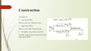
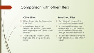
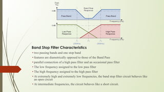
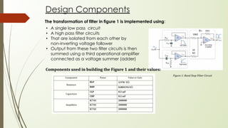
Band Stop Filter Design
Definition:
• Eliminate band of frequencies
• Restricts frequencies inside the stopband
• Allow frequencies around stopband.
• Passes most frequencies unaltered
• Lessens high frequencies
Construction
Consists of:
Low-Pass Filter
Allows only low frequencies
High-Pass Filter
Allows only high frequencies
Amplifier, Op-amp and BJT
Amplify signals from low-pass and
high-pass filters
Scope:
Narrow score filters are utilized in :
Raman spectroscopy
Live sound proliferation
Instrument enhancers
Affecting the remainder of the recurrence range
Different names incorporate :
band limit filter
T-indent filter
band-end filter
band-reject filter
Comparison with other filters
Band Stop Filter
Other filters make the frequencies
they yield
A band-pass filter admits
frequencies within a given band,
rejecting frequencies below it and
above it
The band-pass filters flows the
high-pass and low-pass filters in
series
Other Filters
They basically weaken the
frequencies in the passband
A stop-band filter does the
reverse, rejecting frequencies
within the band and letting
through frequencies outside it
The band stop filter involves the
high-pass and low-pass filters in
equal
Band Stop Filter Characteristics
• two passing bands and one stop band
• features are diametrically opposed to those of the Band Pass
• parallel connection of a high pass filter and an occasional pass filter
• The low frequency assigned to the low pass filter
• The high frequency assigned to the high pass filter
• At extremely high and extremely low frequencies, the band stop filter circuit behaves like
an open circuit
• At intermediate frequencies, the circuit behaves like a short circuit.
Calculations:
Finding RLP
from the Low pass filter using formula:
Finding RHP
from the High pass filter using formula:
Calculations:
Design Components
Figure 1: Band Stop Filter Circuit
The transformation of filter in figure 1 is implemented using:
• A single low pass circuit
• A high pass filter circuits
• That are isolated from each other by
non-inverting voltage follower
• Output from these two filter circuits is then
summed using a third operational amplifier
connected as a voltage summer (adder)
Components used in building the Figure 1 and their values:
Graphs showing the magnitude and the part vs frequency of a particular network created with the ALICE desktop software
suite .
Graph:
Conclusion:
• The Band Stop Filter consists of two pass bands and one stop band
• It uses a high-pass filter and a low-pass filter that is connected in
parallel
• The lower and upper cut off frequencies of the filter depend on the
design of the filter.
• The bandwidth of the filter is nothing but a bandwidth filter
• When the Q factor is high the width of the notch response is small
• This is very popular in communication circuits
Thank You

BAND STOP FILTER.pdf

  • 1.
    Band Stop FilterDesign Definition: • Eliminate band of frequencies • Restricts frequencies inside the stopband • Allow frequencies around stopband. • Passes most frequencies unaltered • Lessens high frequencies
  • 2.
    Construction Consists of: Low-Pass Filter Allowsonly low frequencies High-Pass Filter Allows only high frequencies Amplifier, Op-amp and BJT Amplify signals from low-pass and high-pass filters
  • 3.
    Scope: Narrow score filtersare utilized in : Raman spectroscopy Live sound proliferation Instrument enhancers Affecting the remainder of the recurrence range Different names incorporate : band limit filter T-indent filter band-end filter band-reject filter
  • 4.
    Comparison with otherfilters Band Stop Filter Other filters make the frequencies they yield A band-pass filter admits frequencies within a given band, rejecting frequencies below it and above it The band-pass filters flows the high-pass and low-pass filters in series Other Filters They basically weaken the frequencies in the passband A stop-band filter does the reverse, rejecting frequencies within the band and letting through frequencies outside it The band stop filter involves the high-pass and low-pass filters in equal
  • 5.
    Band Stop FilterCharacteristics • two passing bands and one stop band • features are diametrically opposed to those of the Band Pass • parallel connection of a high pass filter and an occasional pass filter • The low frequency assigned to the low pass filter • The high frequency assigned to the high pass filter • At extremely high and extremely low frequencies, the band stop filter circuit behaves like an open circuit • At intermediate frequencies, the circuit behaves like a short circuit.
  • 6.
    Calculations: Finding RLP from theLow pass filter using formula: Finding RHP from the High pass filter using formula:
  • 7.
  • 8.
    Design Components Figure 1:Band Stop Filter Circuit The transformation of filter in figure 1 is implemented using: • A single low pass circuit • A high pass filter circuits • That are isolated from each other by non-inverting voltage follower • Output from these two filter circuits is then summed using a third operational amplifier connected as a voltage summer (adder) Components used in building the Figure 1 and their values:
  • 9.
    Graphs showing themagnitude and the part vs frequency of a particular network created with the ALICE desktop software suite . Graph:
  • 10.
    Conclusion: • The BandStop Filter consists of two pass bands and one stop band • It uses a high-pass filter and a low-pass filter that is connected in parallel • The lower and upper cut off frequencies of the filter depend on the design of the filter. • The bandwidth of the filter is nothing but a bandwidth filter • When the Q factor is high the width of the notch response is small • This is very popular in communication circuits
  • 11.