Downloaded 988 times
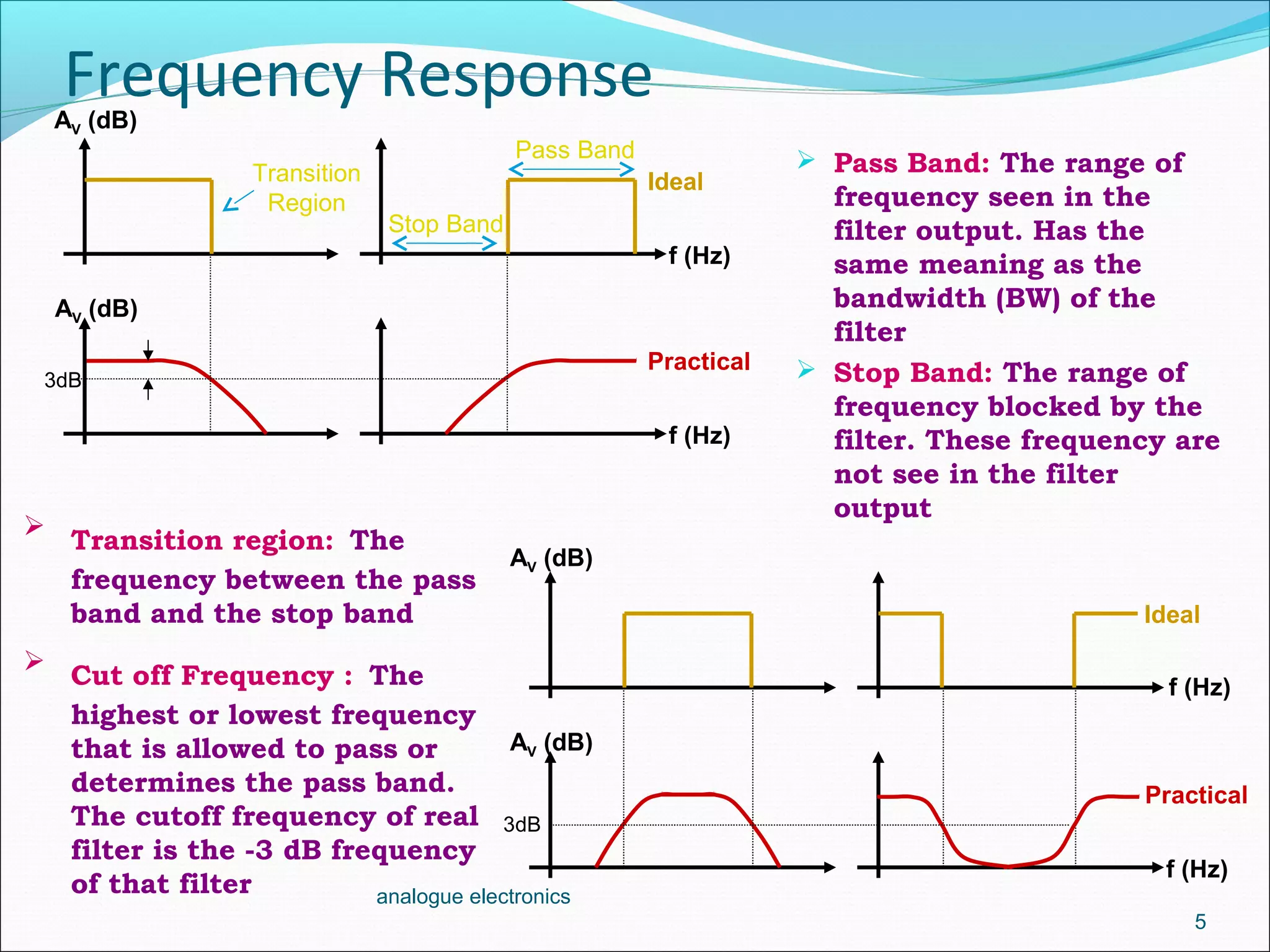
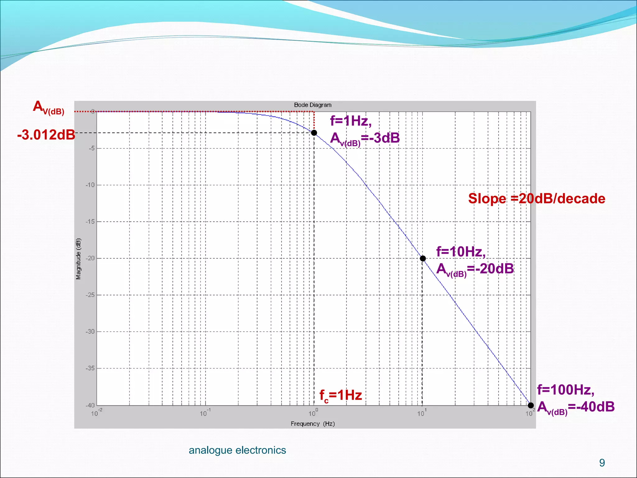
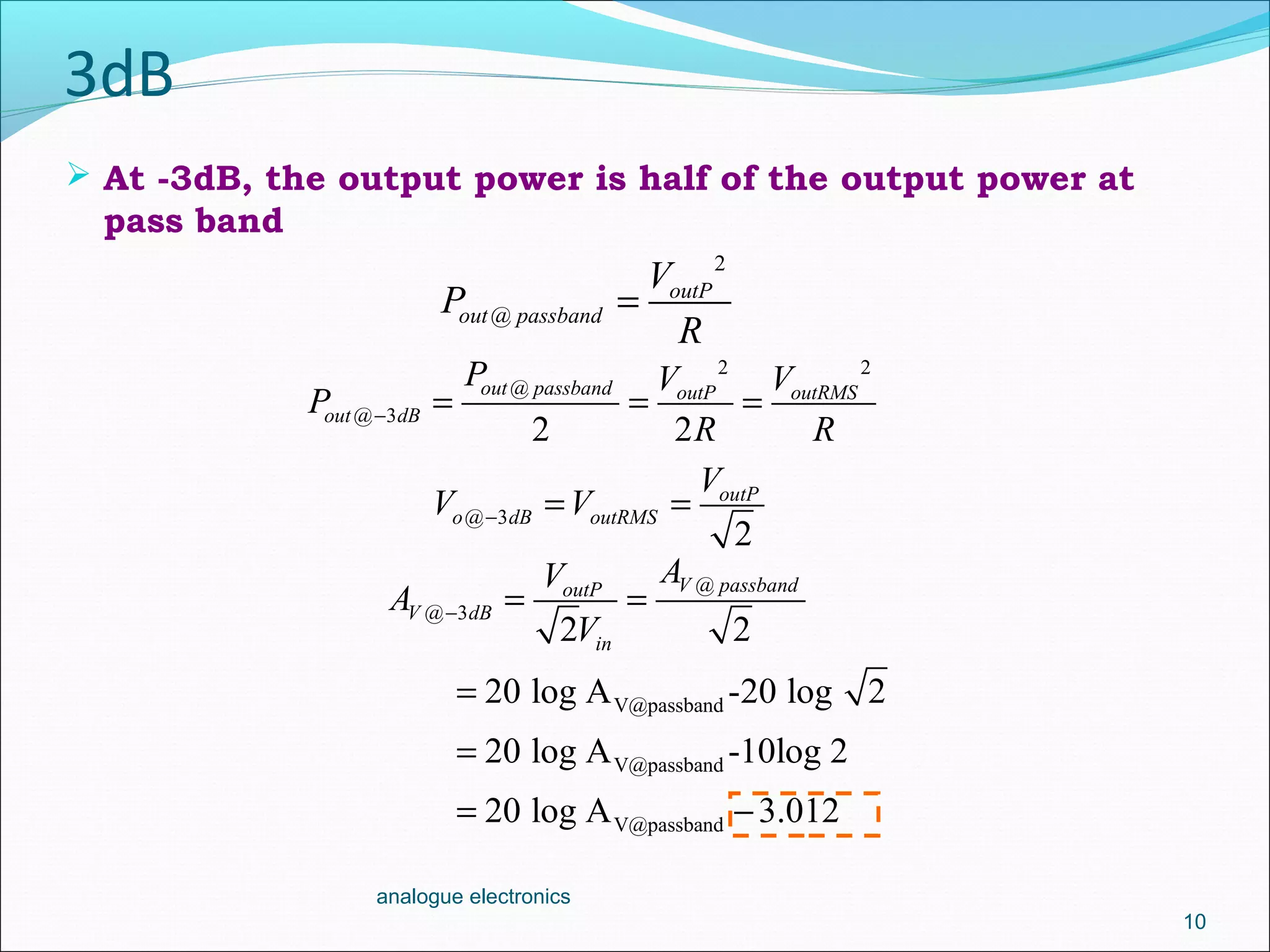
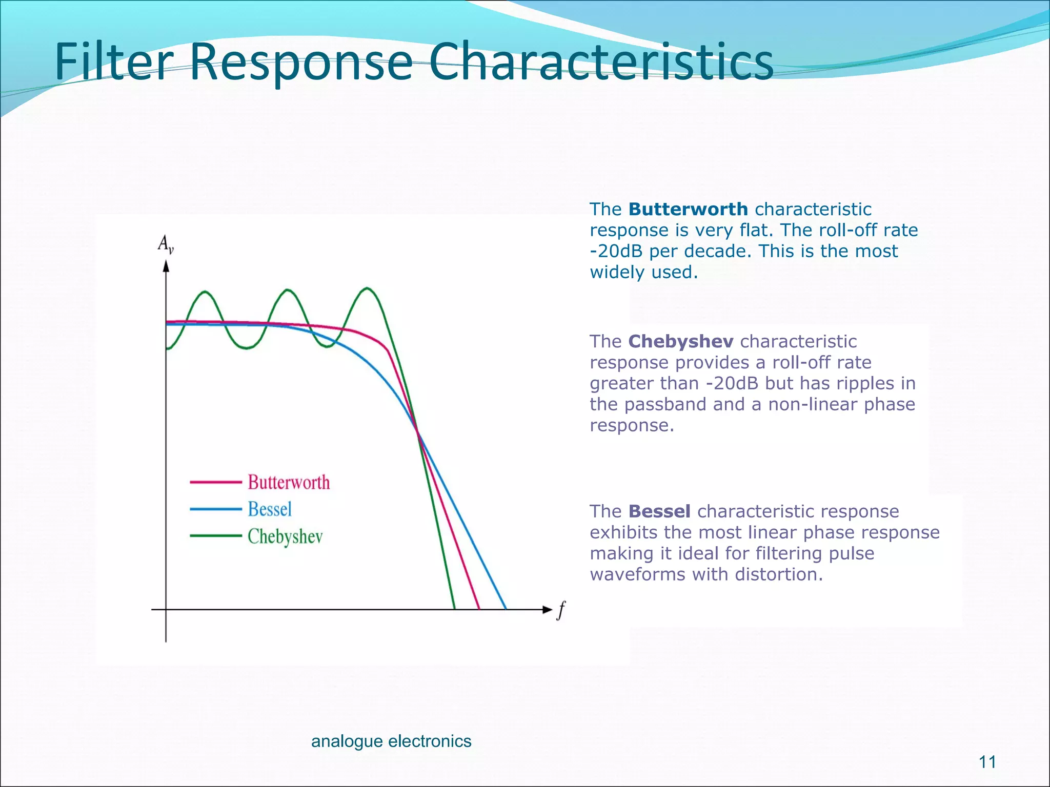
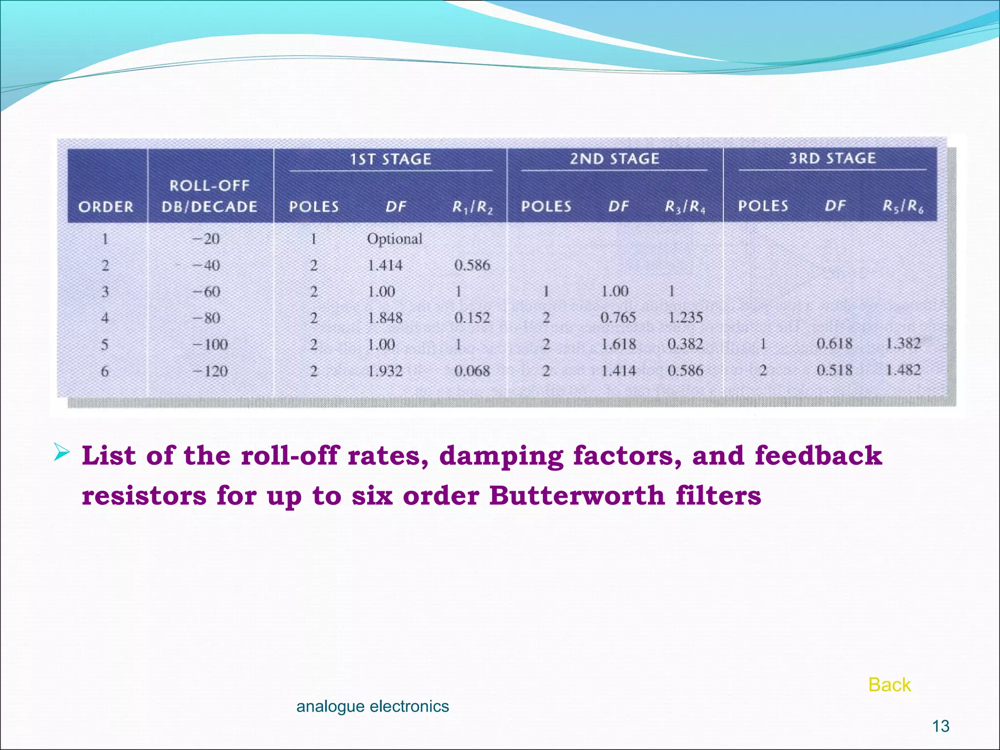
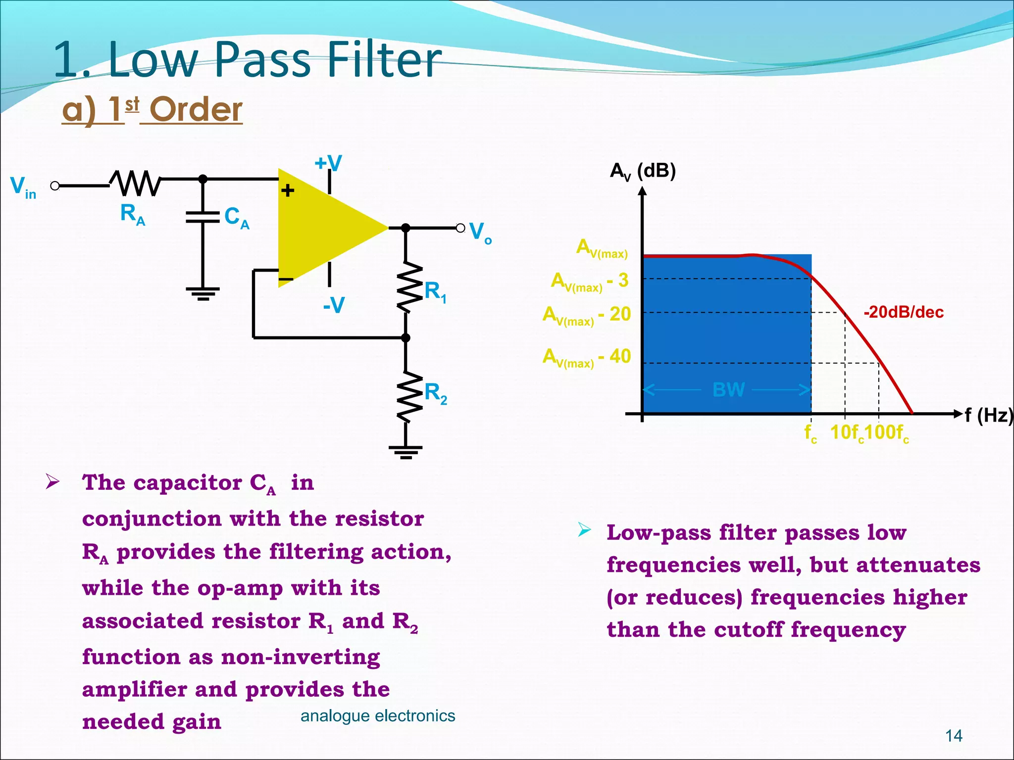
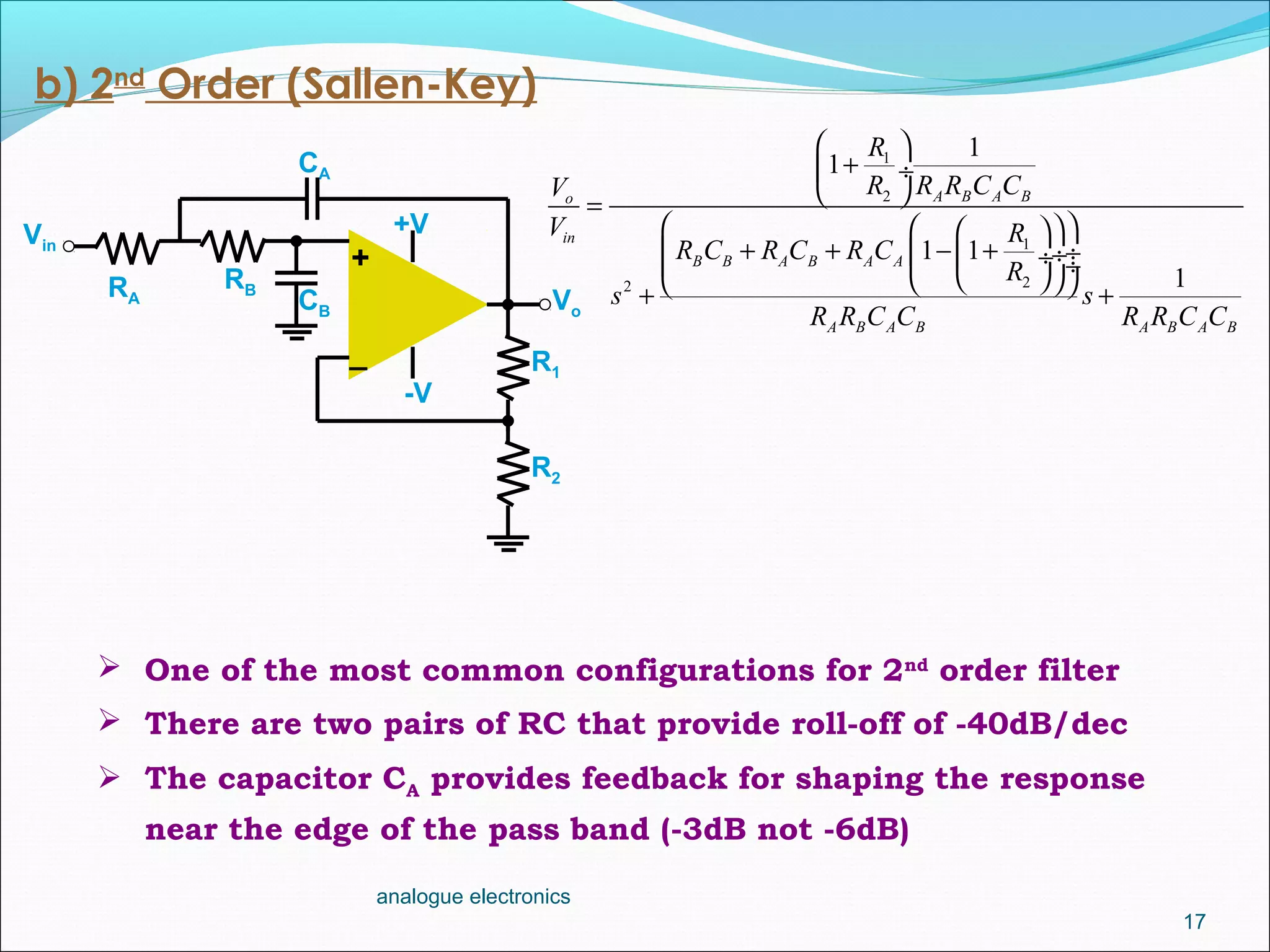
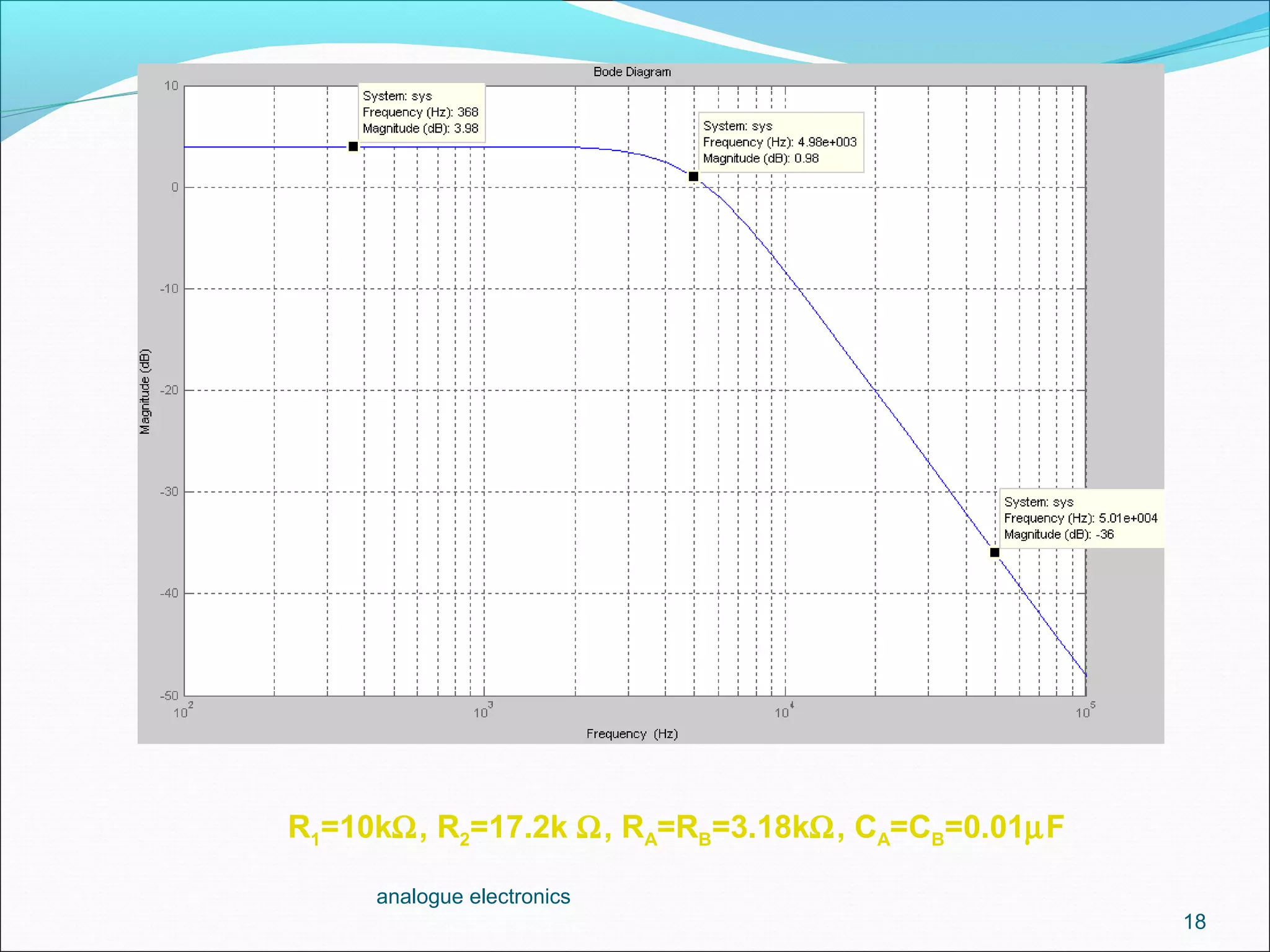
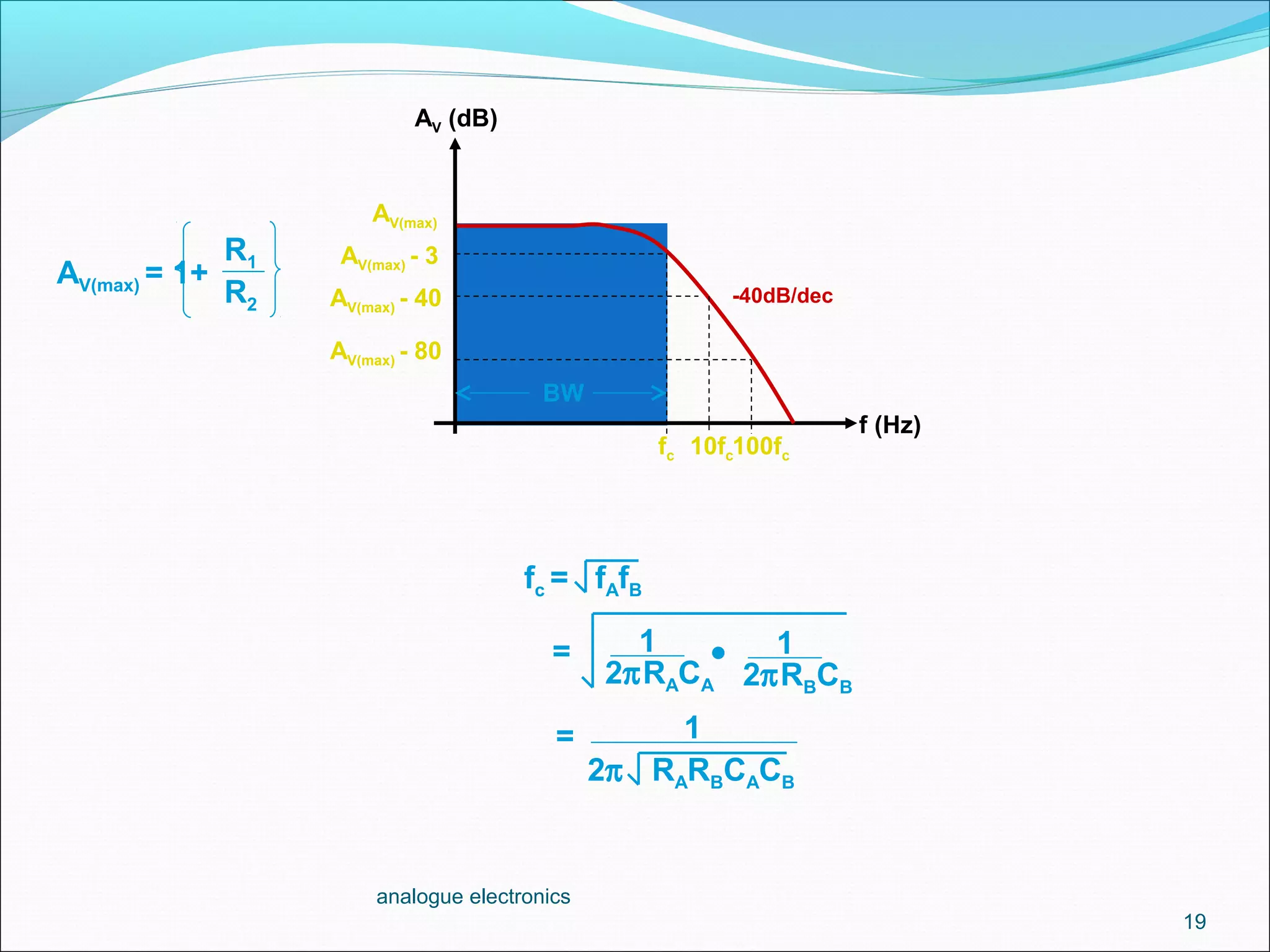
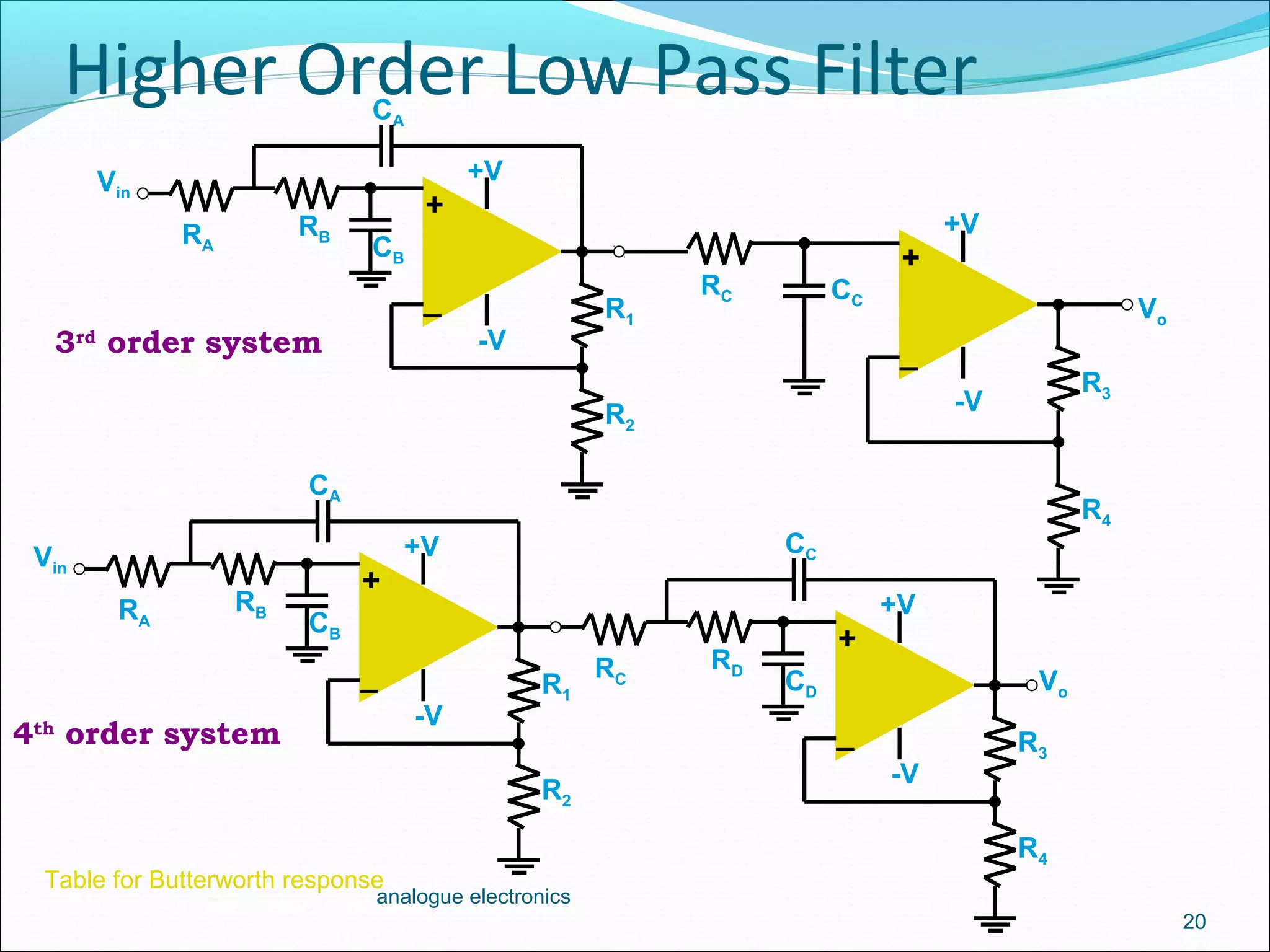

1. Low-pass filters allow low frequencies to pass through but attenuate frequencies higher than the cutoff frequency. They are implemented using a resistor and capacitor in conjunction with an op-amp amplifier. 2. A first-order low-pass filter has a single RC pair and rolls off at -20dB per decade above the cutoff frequency. Higher-order filters use multiple RC stages to achieve steeper roll-offs such as -40dB per decade for a second-order filter. 3. The cutoff frequency is the frequency at which the gain is 3dB below the maximum and is inversely proportional to the product of the resistor and capacitor values in each stage.


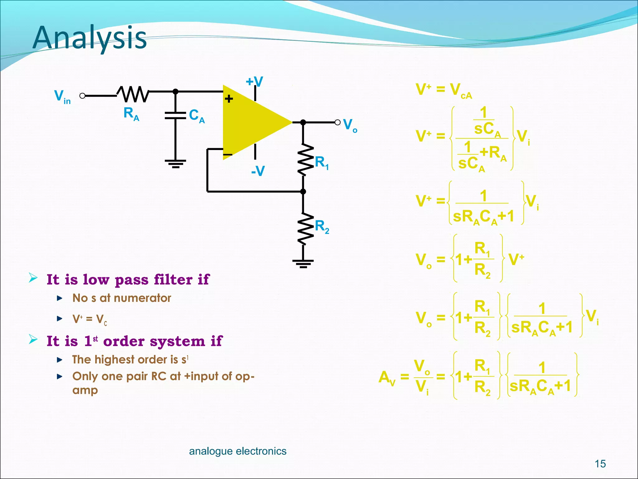
![Vibe Coding vs. Spec-Driven Development [Free Meetup]](https://cdn.slidesharecdn.com/ss_thumbnails/vibecodingvsspecdrivendevelopment-251209105622-43f455e7-thumbnail.jpg?width=640&height=640&fit=bounds)


