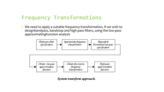
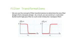
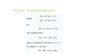
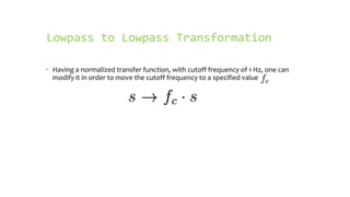
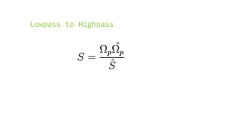
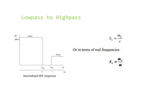
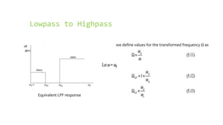
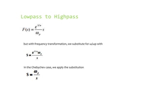
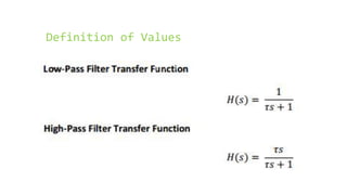
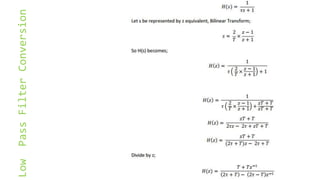
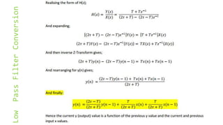
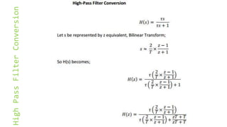
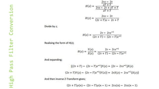
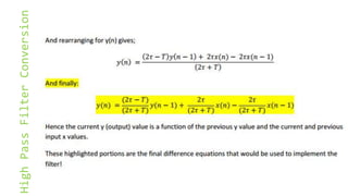
This document discusses frequency transformations that can be used to design bandpass, bandstop, and high-pass filters based on a low-pass filter design. It explains that filters can be transformed from low-pass to other types by applying a suitable frequency transformation. Common transformations include applying substitutions to move the cutoff frequency or replace the frequency variable to transform the response from low-pass to high-pass. The transformations allow filters to be designed by first specifying a normalized low-pass filter and then transforming it.
In this presentation we described about Signal Filtering. If you have any query regarding signal filtering or this presentation then feel free to contact us at:
http://www.siliconmentor.com/
This includes discussion of DSP applications such as two band digital crossover system,woofers, sqawkers, tweeters, interference cancellation in ECG, speech noise reduction, speech coding and compression, CD recording system
the presentation consists of a brief description about ADAPTIVE LINEAR EQUALIZER , its classification and the associated attributes of ZERO FORCING EQUALIZER and MMSE EQUALIZER
The Presentation includes Basics of Non - Uniform Quantization, Companding and different Pulse Code Modulation Techniques. Comparison of Various PCM techniques is done considering various Parameters in Communication Systems.
low pass filters in detail
Low Pass Filters
RC Low Pass Filter
Critical or cutoff frequency
Response curve
Cutoff frequency of RC LPF
RL Low Pass Filter
Cutoff Frequency of RL LPF
Phase Response in Low Pass Filter
Measuring the cutoff frequency of a low pass filterHasnain Ali
It is required to setup an automated test and measurement system for measuring the cutoff frequency of a low pass filter using LabView and estimate the frequency response of the filter.
Implementation and comparison of Low pass filters in Frequency domainZara Tariq
Demonstrating the application results of some low pass filters in a frequency domain.
Pictures and MATLAB code been used in the experiment are taken from the internet.
Fourier Transform : Its power and Limitations – Short Time Fourier Transform – The Gabor Transform - Discrete Time Fourier Transform and filter banks – Continuous Wavelet Transform – Wavelet Transform Ideal Case – Perfect Reconstruction Filter Banks and wavelets – Recursive multi-resolution decomposition – Haar Wavelet – Daubechies Wavelet.
ANALYTIC SIGNAL GENERATION- DIGITAL SIGNAL PROCESSORS AND ARCHITECTURE ...NITHIN KALLE PALLY
In this correspondence we discuss methods to produce the discrete analytic signal from a discrete real-valued signal. Such an analytic signal is complex and contains only positive frequencies. Its projection onto the real axis is the same as the original signal. Our use stems from instantaneous-frequency estimation and time-frequency signal analysis problems. For these problems the negative frequency component of real signals causes unwanted interference. The task of designing a filter to produce an approximation to the ideal analytic signal is not as simple as its formulation might suggest. Our result is that the direct methods of zeroing the negative frequencies, or using Hilbert transform filters, have undesirable defects. We present an alternative which is similar to the "quadrature" filters used in modem design
ANALYTIC SIGNAL GENERATION APPROACH
Since the filter pair’s phase difference is key to the design, we will elect to use finite impulse response (FIR) filters with linear phase. And as is well known, to have linear phase, FIR filters must have impulse responses that are either odd or even symmetric about their midpoint .This fact will prove very useful momentarily
DEFINING THE FREQUENCY RESPONSE
We start by defining our two filters’ identical frequency magnitude response for positive frequencies. Then we will exploit the aforementioned symmetry rules of linear phase filters to find their impulse responses. We construct our bandpass response using two pieces of a sinusoid joined together with a horizontal lines
This presentation will discuss about the introduction, many type of filters, characteristics & causes, and also the spectrum of Vibration Signal Filtering.
It contains the introduction of Low Pass Filter and classification of the same in Signals & Systems point of view. It is a brief presentation done by me as a case study of L.P.F. in college.
2. Frequency Transformations
• We need to apply a suitable frequency transformation, if we wish to
designbandpass, bandstop and high-pass filters, using the low-pass
approximatingfunction analysis
3. Filter Transformations
• We can use the concept of filter transformations to determine the new filter
designs from a lowpass design. As a result, we can construct a 3rd-order
Butterworth high-pass filter or a 5th-order Chebychev bandpass filter!
5. Normalized Lowpass Filter
• When designing a filter, it is common practice to first design a normalized low-
pass filter, and then use a spectral transform to transform that low-pass filter
into a different type of filter (high-pass, band-pass, band-stop).
• The reason for this is because the necessary values for designing lowpass filters
are extensively described and tabulated. From this, filter design can be reduced
to the task of looking up the appropriate values in a table, and then transforming
the filter to meet the specific needs
6. Lowpass to Lowpass Transformation
• Having a normalized transfer function, with cutoff frequency of 1 Hz, one can
modify it in order to move the cutoff frequency to a specified value
11. Lowpass to Highpass
we define values for the transformed frequency Ω as
Equivalent LPF response
12. Lowpass to Highpass
but with frequency transformation, we substitute for ω/ωp with
In the Chebychev case, we apply the substitution
13. Conversion of Low-pass and High-pass
Filter transfer functions from
continuous time to discrete time
difference equations.
• The following converts two filter transfer function that are represented in the
Laplace Space
• (Continuous time) into their discrete time equivalents in the Z-space using the
Bilinear Transform
• (AKA Tustin’s Method), then converts them to difference equations expressing
the current output as a combination of previous inputs and outputs.
Before we consider frequency transform techniques, lets consider the second orderseries-tuned LCR c
We will find that the mathematics for each filter design will be very similar. For example, the difference between a lowpassand highpass filter is essentially an inverse—the frequencies below ωc are mapped into frequencies above ωc—and vice versa
In other words, the transmission through a low-pass filter at one half the cutoff frequency will be equal to the transmission through a (mathematically similar) high-pass filter at twice the cutoff frequency.
Converting a normalized lowpass filter to another lowpass filter allows to set the cutoff frequency of the resulting filter. This is also called frequency scaling.
As an example, the biquadratic transfer functionwill be transformed into:The name biquadratic stems from the fact that the functions has two second order polynoms:
If the filter is given by a circuit and its R, L and C element values found in a table, the transfer function is scaled by changing the element values.The resistance values will stay as they are (a further impedance scaling can be done).The capacitance values are changed according to:The inductance values are changed according to:In the circuit, all capacitances and inductances values are divided by fc
Converting a lowpass filter to a highpass filter is one of the easiest transformations available. To transform to a highpass, we will replace all S in our equation with the following:This operation can be performed using thisMATLAB command:lp2hp
The specification for a high-pass filter includes the passband edge frequency, ωhp,and the stopband edge frequency, ωhs The maximum passband attenuation is Amaxand the minimum stopband attenuation is Amin. The transformation of thehigh-pass specification to an equivalent normalised low-pass specification isachieved by applying the frequency transform SL = 1/s, where SL is the low-passnormalised complex frequency variable. However to account for the process ofnormalization we must replace SL by 1/(s/ω p) =ωp/s.
We calculate the value for ε and n for the filter type chosen using the equivalentnormalised low-pass obtained previously. From these two quantities, we can thenobtain the normalised attenuation function. This must be frequency de-normalisedand the, low-pass to high-pass frequency transformation, performed. To denomalise a Butterworth approximation loss function we used