SlideShare a Scribd company logo
1 of 6
Download to read offline
ISSN 2349-7815
International Journal of Recent Research in Electrical and Electronics Engineering (IJRREEE)
Vol. 4, Issue 2, pp: (99-104), Month: April - June 2017, Available at: www.paperpublications.org
Page | 99
Paper Publications
An Overview of Constant-k Type Filters
1
Rashmi Vaishya, 2
Ashish Choubey
1
M.E. Student (HVPS Engg.), 2
Assistant Professor
1,2
Deptt of Electrical Engineering, JEC Jabalpur , M.P.
Abstract: Power system are designed to operate at a frequency of 50 or 60 Hz. However, certain types of non linear
loads produce current and voltages with frequencies that are integer multiple of the fundamental frequency. These
frequency components known as harmonic pollution and is having adverse effect on the power system network.
Inverter is the part of day to day life for every individual. Energy adversity is of special attention in recent days.
Because of the sine wave output of the inverter, the electronic devices are efficiently operated. Most of the inverters
provide square wave output. Electronic devices run by this inverter may be damaged due to harmonic contents.
Available sine wave inverters are expensive and their output is not so good. Hence the improvement in the square
wave output of the inverter is most essential. For getting pure sine wave output SPWM technique is used in
inverter. The PWM inverter has been the main choice in power electronics because of its simplicity. SPWM is the
mostly used method in motor control and inverter applications. Most of the harmonics can be removed by the
SPWM technique and hence improves the quality of power converter. By using active or passive filters or both, we
can improve the power quality .
Keywords: Filter, Active filter, Passive filter, Low-pass, High-pass, Band-pass, Band-stop, Characteristic
impedance, Cut-off frequency.
I. INTRODUCTION
The concept of filters has been an integral part of the evolution of electrical engineering from the beginning. Several
technological achievements would not have been possible without electrical filters. Because of this prominent role of
filters, much efforts has been expended on the theory, design, and construction of filters. A filter is a circuit that is
designed to pass signals with desired frequencies and reject or attenuate the others. As a frequency-selective device, a
filter can be used to limit the frequency spectrum of a signal to some specified band of frequencies. Filters are the circuits
used to allow to us to select one desired signal out of a multitude of broadcast signals in the environment.
Filters are classified in two types:-
 Active filters
 Passive filters
A filter is a passive filter if it consist of only passive elements R, L and C. It is said to be an active filter if it consists of
active elements (such as transistors and op amps) in addition to passive elements R, L and C. LC filters have been used in
practical applications for more than eight decades.
Passive filters are widely used in power system for harmonic mitigation. In general, they have shunt branches consisting
of passive elements; such as inductors and capacitors which are respectively tuned to the predominant harmonics. Design
procedure for this type of filter is also very simple.
The design of a passive filter requires a precise knowledge of the harmonic producing load and of the power system.
Because passive filters always provide reactive compensation to a degree dictated by the volt-ampere size and voltage of
ISSN 2349-7815
International Journal of Recent Research in Electrical and Electronics Engineering (IJRREEE)
Vol. 4, Issue 2, pp: (99-104), Month: April - June 2017, Available at: www.paperpublications.org
Page | 100
Paper Publications
the capacitor bank used, they can in fact be designed for the double purpose of providing the filtering action and
compensating power factor to the desired level. Thus, passive filter design must take into account expected growth in
harmonic current source or load reconfiguration because it can otherwise be exposed to overloading, which can rapidly
develop into extreme overheating and thermal breakdown.
There are four types of filters whether passive or active:
 Low-pass filters
 High-pass filters
 Band-pass filters
 Band-stop filters
A low-pass filter passes low frequencies and stops high frequencies. A high-pass filter passes high frequencies and rejects
low frequencies. A band-pass filter passes frequencies within a frequency band and blocks or attenuates frequencies
outside the band. A band-stop filter passes frequencies outside a frequency band and blocks or attenuates frequencies
within the band.
II. WORKING OF FILTERS
LOW PASS FILTER:-
It is clear from the figure (1) that with increase in frequency of the signal at the input side, the shunt capacitive reactance
decreases. This will allow more current to be returning back to the source through the low impedance path. At a higher
frequency, the entire input current returns to the source through the shunt branch which becomes practically a short circuit
link at this frequency.
Fig.(1) T-section of Low Pass filter
Thus it is evident that:
 The low pass section can only allow passage of signal through it till the signal frequency is at lower magnitude.
 At higher frequency, the inductive reactance in the series arm also increases to a very high value rendering the
blockage of the input signal. In practice, low pass filter operation is said to be satisfactory for increasing frequencies till
the voltage gain is 0.707 p.u at cut-off frequency .
Fig.(2) LPF response at different frequencies
ISSN 2349-7815
International Journal of Recent Research in Electrical and Electronics Engineering (IJRREEE)
Vol. 4, Issue 2, pp: (99-104), Month: April - June 2017, Available at: www.paperpublications.org
Page | 101
Paper Publications
HIGH PASS FILTER:-
In case of high pass filter, as shown in fig.(3) the action is just the reverse of and with the increase in frequency,
capacitive reactance in the series arm decreases while the inductive reactance in the shunt arm increases. Thus the section
knows the passage of the higher order frequencies blocking the lower order frequencies.
Fig.(3) T-section of High Pass filter
 At lower frequencies, the series capacitor behaves as if a very high reactance while the shunt path offers low
reactance. Figure shows the filter section operating at low frequency and in the corresponding gain frequency plot
indicates the cut-off frequency at the point where the voltage gain equals to 0.707p.u.
Fig. (4) HPF response at different frequencies
BAND PASS FILTER:-
A Band pass filter is combination of two parallel tuned circuits as shown in figure (5). This is a special type of LC filter
along-with a particular bandwidth frequency to be allowed through it.
Fig. (5) T-section of Band pass filter
The operation of the filter initiated when the shunt arm as well as the series arms are in resonance. At resonance, the shunt
arm behaves as a rejector circuit offering a very high impedance in the shunt arm while the series arm at resonance offers
least impedance i.e. a acceptor circuit; thus, any electric signal, incident at the input of the filter allows its transmission
through it within the pass band.
ISSN 2349-7815
International Journal of Recent Research in Electrical and Electronics Engineering (IJRREEE)
Vol. 4, Issue 2, pp: (99-104), Month: April - June 2017, Available at: www.paperpublications.org
Page | 102
Paper Publications
Fig. (6) Band-Pass filter response at different frequencies
BAND STOP FILTER:-
A band stop filter as shown in figure (7) in its simplest form, is a tandem of a low pass filter with a high pass filter. Here,
the cut-off frequency of high pass filter is higher than the cut-off frequency of the low pass filter. The overlapping
attenuation band of the two filters then constitutes the stop band of the band stop filter.
Fig. (7) T-section of Band stop filter
In practice the action of LPF and HPF are combined into a single band stop filter. Operation is initiated when resonance
occurs so that shunt impedance becomes minimum and series impedance becomes maximum. Thus incident signal is
blocked at this particular condition.
Fig. (8) Band-Stop filter response at different frequencies
III. CHARACTERISTIC IMPEDANCE AND PROPOGATION CONSTANT
In a two-port network, as shown in fig. (9) if two impedances and are such that is the driving point impedance
at port 1 with impedance connected across port 2, and is the driving point impedance at port 2 with impedance
connected across port 1, then the impedances and are called image impedances of the network. For symmetrical
network, image impedances are equal to each other i.e. = ) and is called the characteristic impedance of the filter
.
Fig. (9) T-network interposed between source and load
ISSN 2349-7815
International Journal of Recent Research in Electrical and Electronics Engineering (IJRREEE)
Vol. 4, Issue 2, pp: (99-104), Month: April - June 2017, Available at: www.paperpublications.org
Page | 103
Paper Publications
For symmetrical T network, the value of input impedance when it is terminated by characteristic impedance is given
by
= √( )
As input and output impedances are equal under termination,
⁄ ⁄
then ⁄ = ⁄
where is a complex number and is defined as
= propogation constant
= attenuation constant
= phase constant
The purpose of a filter network is to transmit or pass a desired frequency band without loss and stop or completely at
attenuate all undesired frequencies.
(a) (b)
(c) (d)
Fig.(10) Characteristic impedance profile of (a) LPF (b) HPF (c) BPF (d) BSF
IV. DESIGN OF CONSTANT-K FILTERS
In constant-k type filter, the series and shunt impedances ( and ) are such that
Where is a real number and independent of frequency. It is known as design impedance of the section. Any filter,
where this relationship is maintained is known as constant or prototype filter.
The design values of elements for different types of constant-k prototype filters are as follows:-
ISSN 2349-7815
International Journal of Recent Research in Electrical and Electronics Engineering (IJRREEE)
Vol. 4, Issue 2, pp: (99-104), Month: April - June 2017, Available at: www.paperpublications.org
Page | 104
Paper Publications
Low-pass section
√ ;
√
⁄ ; ⁄ ;
High-pass section
√ ;
√
⁄ ; ⁄ ;
Band-pass section
√ √ ;
;
Band-stop section
√ √ ;
;
V. QUALITIES AND LIMITATIONS OF CONSTANT-K FILTER
The constant-k filters have qualities and limitations:-
Qualities:
 They are easy to design (the configurations and relations are very simple).
 The attenuation in the stop band tends to infinity at frequencies that are too far away from the cut-off frequency.
Limitations:
 The attenuation increases very slowly in the stop band, near the pass band; therefore the stop band and the pass band
not clearly enough delimited.
 In the pass band the characteristic impedance varies a lot with frequency, so the filter is far away from being matched;
as a consequence, the attenuation will not be zero in the pass band.
There are the few ways to eliminate these limitations:
 A way is to replace the constant-k filters with more complex filters (for example, the m-derived filters).
 Another way is to use more sections connected in chain. The sections must have the same characteristic impedance (in
order to reduce the non-matching attenuations), therefore they will have the same cut-off frequency. Unfortunately, using
more sections in chain won’t solve the problem of correct matching; when the attenuation increases in the stop
band(desired effect), it also increases in the pass-band too(non-desired effect).
REFERENCES
[1] Dr. Abhijit Chakrabarti, Fifth edition, “Circuit theory (Analysis and Synthesis)”, Dhanpat Rai & CO. (PVT) LTD.
[2] D Roy Choudhary, “Network and Systems” New age international (P) limited publishers..
[3] Charles K Alexender, Mathew N O Sadiku , “ Fundamentals of electric circuits”, Third edition, The McGraw Hill
Companies.

More Related Content

What's hot

Amplifier (Transformer Coupled)
Amplifier (Transformer Coupled)Amplifier (Transformer Coupled)
Amplifier (Transformer Coupled)Arpan Bose
 
Overview of Crystal Oscillator Circuit Working and Its Application
Overview of Crystal Oscillator Circuit Working and Its ApplicationOverview of Crystal Oscillator Circuit Working and Its Application
Overview of Crystal Oscillator Circuit Working and Its Applicationelprocus
 
Need of starters in dc motors
Need of starters in dc motorsNeed of starters in dc motors
Need of starters in dc motorsFurqan Sadiq
 
Rc circuits and its transient response
Rc circuits and its transient responseRc circuits and its transient response
Rc circuits and its transient responseHamzaAbbas43
 
7.Active Filters using Opamp
7.Active Filters using Opamp7.Active Filters using Opamp
7.Active Filters using OpampINDIAN NAVY
 
Voltage regulation
Voltage regulationVoltage regulation
Voltage regulationpopet
 
Schmitt trigger basics
Schmitt trigger  basicsSchmitt trigger  basics
Schmitt trigger basicsSAQUIB AHMAD
 
Slew rate, Open and closed loop configurations
Slew rate, Open and closed loop configurationsSlew rate, Open and closed loop configurations
Slew rate, Open and closed loop configurationsGOWRISHANKAR RAJU
 
Instrument Transformer Presentation
Instrument Transformer PresentationInstrument Transformer Presentation
Instrument Transformer PresentationRishi Raj
 

What's hot (20)

Amplifier (Transformer Coupled)
Amplifier (Transformer Coupled)Amplifier (Transformer Coupled)
Amplifier (Transformer Coupled)
 
Overview of Crystal Oscillator Circuit Working and Its Application
Overview of Crystal Oscillator Circuit Working and Its ApplicationOverview of Crystal Oscillator Circuit Working and Its Application
Overview of Crystal Oscillator Circuit Working and Its Application
 
Need of starters in dc motors
Need of starters in dc motorsNeed of starters in dc motors
Need of starters in dc motors
 
Digital voltmeter
Digital voltmeterDigital voltmeter
Digital voltmeter
 
Presentation on JFET
Presentation on JFETPresentation on JFET
Presentation on JFET
 
Filters
FiltersFilters
Filters
 
Unit 2
Unit 2Unit 2
Unit 2
 
Rc circuits and its transient response
Rc circuits and its transient responseRc circuits and its transient response
Rc circuits and its transient response
 
7.Active Filters using Opamp
7.Active Filters using Opamp7.Active Filters using Opamp
7.Active Filters using Opamp
 
Voltage regulation
Voltage regulationVoltage regulation
Voltage regulation
 
Power Meters
Power MetersPower Meters
Power Meters
 
Op amp
Op ampOp amp
Op amp
 
Schmitt trigger basics
Schmitt trigger  basicsSchmitt trigger  basics
Schmitt trigger basics
 
Skin effect
Skin effectSkin effect
Skin effect
 
Slew rate, Open and closed loop configurations
Slew rate, Open and closed loop configurationsSlew rate, Open and closed loop configurations
Slew rate, Open and closed loop configurations
 
Active filter
Active filterActive filter
Active filter
 
filters
filtersfilters
filters
 
Types of cro
Types of croTypes of cro
Types of cro
 
Instrument Transformer Presentation
Instrument Transformer PresentationInstrument Transformer Presentation
Instrument Transformer Presentation
 
Thevenin's theorem
Thevenin's theoremThevenin's theorem
Thevenin's theorem
 

Similar to An Overview of Constant-k Type Filters

Ijarcet vol-2-issue-3-861-866
Ijarcet vol-2-issue-3-861-866Ijarcet vol-2-issue-3-861-866
Ijarcet vol-2-issue-3-861-866Editor IJARCET
 
Performance Analysis of Constant-K Low-Pass and Band-Pass Filters in a Uni-Po...
Performance Analysis of Constant-K Low-Pass and Band-Pass Filters in a Uni-Po...Performance Analysis of Constant-K Low-Pass and Band-Pass Filters in a Uni-Po...
Performance Analysis of Constant-K Low-Pass and Band-Pass Filters in a Uni-Po...paperpublications3
 
Paper id 36201528
Paper id 36201528Paper id 36201528
Paper id 36201528IJRAT
 
Project report on RF Filter Design
Project report on RF Filter DesignProject report on RF Filter Design
Project report on RF Filter Designvaibhavjk
 
Magnetic Femtotesla Inductor Coil Sensor for ELF Noise Signals-( 0.1Hz to3.0 Hz)
Magnetic Femtotesla Inductor Coil Sensor for ELF Noise Signals-( 0.1Hz to3.0 Hz)Magnetic Femtotesla Inductor Coil Sensor for ELF Noise Signals-( 0.1Hz to3.0 Hz)
Magnetic Femtotesla Inductor Coil Sensor for ELF Noise Signals-( 0.1Hz to3.0 Hz)IOSR Journals
 
Study Of Different Passive Filter- A Review
Study Of Different Passive Filter- A ReviewStudy Of Different Passive Filter- A Review
Study Of Different Passive Filter- A ReviewIRJET Journal
 
The Harmonic Mitigation in Induction Furnace Using Hybrid Filter
The Harmonic Mitigation in Induction Furnace Using Hybrid FilterThe Harmonic Mitigation in Induction Furnace Using Hybrid Filter
The Harmonic Mitigation in Induction Furnace Using Hybrid Filterpaperpublications3
 
Exp2 passive band pass and band-stop filter
Exp2 passive band pass and band-stop filterExp2 passive band pass and band-stop filter
Exp2 passive band pass and band-stop filterSarah Krystelle
 
5. An analog filer has system fnction Ha(s)--a (a) (10 pts,) Comvert .pdf
5. An analog filer has system fnction Ha(s)--a (a) (10 pts,) Comvert .pdf5. An analog filer has system fnction Ha(s)--a (a) (10 pts,) Comvert .pdf
5. An analog filer has system fnction Ha(s)--a (a) (10 pts,) Comvert .pdfinfo324235
 
Signal Integrity Asif
Signal Integrity AsifSignal Integrity Asif
Signal Integrity AsifMohammed Asif
 
Inductanceless high order low frequency filters for medical applications
Inductanceless high order low frequency filters for medical  applicationsInductanceless high order low frequency filters for medical  applications
Inductanceless high order low frequency filters for medical applicationsIJECEIAES
 
Rec101 unit v communication engg
Rec101 unit v communication enggRec101 unit v communication engg
Rec101 unit v communication enggDr Naim R Kidwai
 
IRJET- A Review on Microstrip Filter for the Application in Communication System
IRJET- A Review on Microstrip Filter for the Application in Communication SystemIRJET- A Review on Microstrip Filter for the Application in Communication System
IRJET- A Review on Microstrip Filter for the Application in Communication SystemIRJET Journal
 
Applications of RLC Circuits
Applications of RLC CircuitsApplications of RLC Circuits
Applications of RLC Circuitszain saleem
 
Fianl Year Project Report
Fianl Year Project ReportFianl Year Project Report
Fianl Year Project ReportShruti Nadkarni
 

Similar to An Overview of Constant-k Type Filters (20)

Improved Fully Differential Low Power Active Filter
Improved Fully Differential Low Power Active FilterImproved Fully Differential Low Power Active Filter
Improved Fully Differential Low Power Active Filter
 
Ijarcet vol-2-issue-3-861-866
Ijarcet vol-2-issue-3-861-866Ijarcet vol-2-issue-3-861-866
Ijarcet vol-2-issue-3-861-866
 
Performance Analysis of Constant-K Low-Pass and Band-Pass Filters in a Uni-Po...
Performance Analysis of Constant-K Low-Pass and Band-Pass Filters in a Uni-Po...Performance Analysis of Constant-K Low-Pass and Band-Pass Filters in a Uni-Po...
Performance Analysis of Constant-K Low-Pass and Band-Pass Filters in a Uni-Po...
 
Paper id 36201528
Paper id 36201528Paper id 36201528
Paper id 36201528
 
Project report on RF Filter Design
Project report on RF Filter DesignProject report on RF Filter Design
Project report on RF Filter Design
 
Magnetic Femtotesla Inductor Coil Sensor for ELF Noise Signals-( 0.1Hz to3.0 Hz)
Magnetic Femtotesla Inductor Coil Sensor for ELF Noise Signals-( 0.1Hz to3.0 Hz)Magnetic Femtotesla Inductor Coil Sensor for ELF Noise Signals-( 0.1Hz to3.0 Hz)
Magnetic Femtotesla Inductor Coil Sensor for ELF Noise Signals-( 0.1Hz to3.0 Hz)
 
Study Of Different Passive Filter- A Review
Study Of Different Passive Filter- A ReviewStudy Of Different Passive Filter- A Review
Study Of Different Passive Filter- A Review
 
The Harmonic Mitigation in Induction Furnace Using Hybrid Filter
The Harmonic Mitigation in Induction Furnace Using Hybrid FilterThe Harmonic Mitigation in Induction Furnace Using Hybrid Filter
The Harmonic Mitigation in Induction Furnace Using Hybrid Filter
 
Oj2423402345
Oj2423402345Oj2423402345
Oj2423402345
 
Tuned amplifiers
Tuned amplifiersTuned amplifiers
Tuned amplifiers
 
Exp2 passive band pass and band-stop filter
Exp2 passive band pass and band-stop filterExp2 passive band pass and band-stop filter
Exp2 passive band pass and band-stop filter
 
5. An analog filer has system fnction Ha(s)--a (a) (10 pts,) Comvert .pdf
5. An analog filer has system fnction Ha(s)--a (a) (10 pts,) Comvert .pdf5. An analog filer has system fnction Ha(s)--a (a) (10 pts,) Comvert .pdf
5. An analog filer has system fnction Ha(s)--a (a) (10 pts,) Comvert .pdf
 
Signal Integrity Asif
Signal Integrity AsifSignal Integrity Asif
Signal Integrity Asif
 
Inductanceless high order low frequency filters for medical applications
Inductanceless high order low frequency filters for medical  applicationsInductanceless high order low frequency filters for medical  applications
Inductanceless high order low frequency filters for medical applications
 
Ijecce 2241 final
Ijecce 2241 finalIjecce 2241 final
Ijecce 2241 final
 
Ih3514441454
Ih3514441454Ih3514441454
Ih3514441454
 
Rec101 unit v communication engg
Rec101 unit v communication enggRec101 unit v communication engg
Rec101 unit v communication engg
 
IRJET- A Review on Microstrip Filter for the Application in Communication System
IRJET- A Review on Microstrip Filter for the Application in Communication SystemIRJET- A Review on Microstrip Filter for the Application in Communication System
IRJET- A Review on Microstrip Filter for the Application in Communication System
 
Applications of RLC Circuits
Applications of RLC CircuitsApplications of RLC Circuits
Applications of RLC Circuits
 
Fianl Year Project Report
Fianl Year Project ReportFianl Year Project Report
Fianl Year Project Report
 

Recently uploaded

Generative AI or GenAI technology based PPT
Generative AI or GenAI technology based PPTGenerative AI or GenAI technology based PPT
Generative AI or GenAI technology based PPTbhaskargani46
 
The Most Attractive Pune Call Girls Budhwar Peth 8250192130 Will You Miss Thi...
The Most Attractive Pune Call Girls Budhwar Peth 8250192130 Will You Miss Thi...The Most Attractive Pune Call Girls Budhwar Peth 8250192130 Will You Miss Thi...
The Most Attractive Pune Call Girls Budhwar Peth 8250192130 Will You Miss Thi...ranjana rawat
 
Double Revolving field theory-how the rotor develops torque
Double Revolving field theory-how the rotor develops torqueDouble Revolving field theory-how the rotor develops torque
Double Revolving field theory-how the rotor develops torqueBhangaleSonal
 
Booking open Available Pune Call Girls Pargaon 6297143586 Call Hot Indian Gi...
Booking open Available Pune Call Girls Pargaon  6297143586 Call Hot Indian Gi...Booking open Available Pune Call Girls Pargaon  6297143586 Call Hot Indian Gi...
Booking open Available Pune Call Girls Pargaon 6297143586 Call Hot Indian Gi...Call Girls in Nagpur High Profile
 
VIP Model Call Girls Kothrud ( Pune ) Call ON 8005736733 Starting From 5K to ...
VIP Model Call Girls Kothrud ( Pune ) Call ON 8005736733 Starting From 5K to ...VIP Model Call Girls Kothrud ( Pune ) Call ON 8005736733 Starting From 5K to ...
VIP Model Call Girls Kothrud ( Pune ) Call ON 8005736733 Starting From 5K to ...SUHANI PANDEY
 
Call Girls In Bangalore ☎ 7737669865 🥵 Book Your One night Stand
Call Girls In Bangalore ☎ 7737669865 🥵 Book Your One night StandCall Girls In Bangalore ☎ 7737669865 🥵 Book Your One night Stand
Call Girls In Bangalore ☎ 7737669865 🥵 Book Your One night Standamitlee9823
 
Online banking management system project.pdf
Online banking management system project.pdfOnline banking management system project.pdf
Online banking management system project.pdfKamal Acharya
 
Unleashing the Power of the SORA AI lastest leap
Unleashing the Power of the SORA AI lastest leapUnleashing the Power of the SORA AI lastest leap
Unleashing the Power of the SORA AI lastest leapRishantSharmaFr
 
Call for Papers - African Journal of Biological Sciences, E-ISSN: 2663-2187, ...
Call for Papers - African Journal of Biological Sciences, E-ISSN: 2663-2187, ...Call for Papers - African Journal of Biological Sciences, E-ISSN: 2663-2187, ...
Call for Papers - African Journal of Biological Sciences, E-ISSN: 2663-2187, ...Christo Ananth
 
KubeKraft presentation @CloudNativeHooghly
KubeKraft presentation @CloudNativeHooghlyKubeKraft presentation @CloudNativeHooghly
KubeKraft presentation @CloudNativeHooghlysanyuktamishra911
 
CCS335 _ Neural Networks and Deep Learning Laboratory_Lab Complete Record
CCS335 _ Neural Networks and Deep Learning Laboratory_Lab Complete RecordCCS335 _ Neural Networks and Deep Learning Laboratory_Lab Complete Record
CCS335 _ Neural Networks and Deep Learning Laboratory_Lab Complete RecordAsst.prof M.Gokilavani
 
Unit 1 - Soil Classification and Compaction.pdf
Unit 1 - Soil Classification and Compaction.pdfUnit 1 - Soil Classification and Compaction.pdf
Unit 1 - Soil Classification and Compaction.pdfRagavanV2
 
data_management_and _data_science_cheat_sheet.pdf
data_management_and _data_science_cheat_sheet.pdfdata_management_and _data_science_cheat_sheet.pdf
data_management_and _data_science_cheat_sheet.pdfJiananWang21
 
XXXXXXXXXXXXXXXXXXXXXXXXXXXXXXXXXXXXXXXXXXXXXXXXXXXX
XXXXXXXXXXXXXXXXXXXXXXXXXXXXXXXXXXXXXXXXXXXXXXXXXXXXXXXXXXXXXXXXXXXXXXXXXXXXXXXXXXXXXXXXXXXXXXXXXXXXXXXX
XXXXXXXXXXXXXXXXXXXXXXXXXXXXXXXXXXXXXXXXXXXXXXXXXXXXssuser89054b
 
Call Girls Pimpri Chinchwad Call Me 7737669865 Budget Friendly No Advance Boo...
Call Girls Pimpri Chinchwad Call Me 7737669865 Budget Friendly No Advance Boo...Call Girls Pimpri Chinchwad Call Me 7737669865 Budget Friendly No Advance Boo...
Call Girls Pimpri Chinchwad Call Me 7737669865 Budget Friendly No Advance Boo...roncy bisnoi
 

Recently uploaded (20)

Generative AI or GenAI technology based PPT
Generative AI or GenAI technology based PPTGenerative AI or GenAI technology based PPT
Generative AI or GenAI technology based PPT
 
The Most Attractive Pune Call Girls Budhwar Peth 8250192130 Will You Miss Thi...
The Most Attractive Pune Call Girls Budhwar Peth 8250192130 Will You Miss Thi...The Most Attractive Pune Call Girls Budhwar Peth 8250192130 Will You Miss Thi...
The Most Attractive Pune Call Girls Budhwar Peth 8250192130 Will You Miss Thi...
 
Double Revolving field theory-how the rotor develops torque
Double Revolving field theory-how the rotor develops torqueDouble Revolving field theory-how the rotor develops torque
Double Revolving field theory-how the rotor develops torque
 
Booking open Available Pune Call Girls Pargaon 6297143586 Call Hot Indian Gi...
Booking open Available Pune Call Girls Pargaon  6297143586 Call Hot Indian Gi...Booking open Available Pune Call Girls Pargaon  6297143586 Call Hot Indian Gi...
Booking open Available Pune Call Girls Pargaon 6297143586 Call Hot Indian Gi...
 
VIP Model Call Girls Kothrud ( Pune ) Call ON 8005736733 Starting From 5K to ...
VIP Model Call Girls Kothrud ( Pune ) Call ON 8005736733 Starting From 5K to ...VIP Model Call Girls Kothrud ( Pune ) Call ON 8005736733 Starting From 5K to ...
VIP Model Call Girls Kothrud ( Pune ) Call ON 8005736733 Starting From 5K to ...
 
Call Now ≽ 9953056974 ≼🔝 Call Girls In New Ashok Nagar ≼🔝 Delhi door step de...
Call Now ≽ 9953056974 ≼🔝 Call Girls In New Ashok Nagar  ≼🔝 Delhi door step de...Call Now ≽ 9953056974 ≼🔝 Call Girls In New Ashok Nagar  ≼🔝 Delhi door step de...
Call Now ≽ 9953056974 ≼🔝 Call Girls In New Ashok Nagar ≼🔝 Delhi door step de...
 
Call Girls in Ramesh Nagar Delhi 💯 Call Us 🔝9953056974 🔝 Escort Service
Call Girls in Ramesh Nagar Delhi 💯 Call Us 🔝9953056974 🔝 Escort ServiceCall Girls in Ramesh Nagar Delhi 💯 Call Us 🔝9953056974 🔝 Escort Service
Call Girls in Ramesh Nagar Delhi 💯 Call Us 🔝9953056974 🔝 Escort Service
 
Water Industry Process Automation & Control Monthly - April 2024
Water Industry Process Automation & Control Monthly - April 2024Water Industry Process Automation & Control Monthly - April 2024
Water Industry Process Automation & Control Monthly - April 2024
 
Call Girls In Bangalore ☎ 7737669865 🥵 Book Your One night Stand
Call Girls In Bangalore ☎ 7737669865 🥵 Book Your One night StandCall Girls In Bangalore ☎ 7737669865 🥵 Book Your One night Stand
Call Girls In Bangalore ☎ 7737669865 🥵 Book Your One night Stand
 
Online banking management system project.pdf
Online banking management system project.pdfOnline banking management system project.pdf
Online banking management system project.pdf
 
Unleashing the Power of the SORA AI lastest leap
Unleashing the Power of the SORA AI lastest leapUnleashing the Power of the SORA AI lastest leap
Unleashing the Power of the SORA AI lastest leap
 
(INDIRA) Call Girl Aurangabad Call Now 8617697112 Aurangabad Escorts 24x7
(INDIRA) Call Girl Aurangabad Call Now 8617697112 Aurangabad Escorts 24x7(INDIRA) Call Girl Aurangabad Call Now 8617697112 Aurangabad Escorts 24x7
(INDIRA) Call Girl Aurangabad Call Now 8617697112 Aurangabad Escorts 24x7
 
Call for Papers - African Journal of Biological Sciences, E-ISSN: 2663-2187, ...
Call for Papers - African Journal of Biological Sciences, E-ISSN: 2663-2187, ...Call for Papers - African Journal of Biological Sciences, E-ISSN: 2663-2187, ...
Call for Papers - African Journal of Biological Sciences, E-ISSN: 2663-2187, ...
 
KubeKraft presentation @CloudNativeHooghly
KubeKraft presentation @CloudNativeHooghlyKubeKraft presentation @CloudNativeHooghly
KubeKraft presentation @CloudNativeHooghly
 
CCS335 _ Neural Networks and Deep Learning Laboratory_Lab Complete Record
CCS335 _ Neural Networks and Deep Learning Laboratory_Lab Complete RecordCCS335 _ Neural Networks and Deep Learning Laboratory_Lab Complete Record
CCS335 _ Neural Networks and Deep Learning Laboratory_Lab Complete Record
 
Roadmap to Membership of RICS - Pathways and Routes
Roadmap to Membership of RICS - Pathways and RoutesRoadmap to Membership of RICS - Pathways and Routes
Roadmap to Membership of RICS - Pathways and Routes
 
Unit 1 - Soil Classification and Compaction.pdf
Unit 1 - Soil Classification and Compaction.pdfUnit 1 - Soil Classification and Compaction.pdf
Unit 1 - Soil Classification and Compaction.pdf
 
data_management_and _data_science_cheat_sheet.pdf
data_management_and _data_science_cheat_sheet.pdfdata_management_and _data_science_cheat_sheet.pdf
data_management_and _data_science_cheat_sheet.pdf
 
XXXXXXXXXXXXXXXXXXXXXXXXXXXXXXXXXXXXXXXXXXXXXXXXXXXX
XXXXXXXXXXXXXXXXXXXXXXXXXXXXXXXXXXXXXXXXXXXXXXXXXXXXXXXXXXXXXXXXXXXXXXXXXXXXXXXXXXXXXXXXXXXXXXXXXXXXXXXX
XXXXXXXXXXXXXXXXXXXXXXXXXXXXXXXXXXXXXXXXXXXXXXXXXXXX
 
Call Girls Pimpri Chinchwad Call Me 7737669865 Budget Friendly No Advance Boo...
Call Girls Pimpri Chinchwad Call Me 7737669865 Budget Friendly No Advance Boo...Call Girls Pimpri Chinchwad Call Me 7737669865 Budget Friendly No Advance Boo...
Call Girls Pimpri Chinchwad Call Me 7737669865 Budget Friendly No Advance Boo...
 

An Overview of Constant-k Type Filters

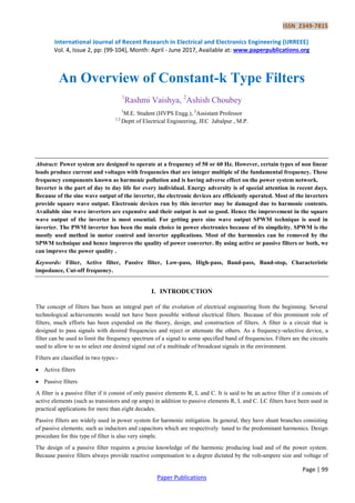
  • 1. ISSN 2349-7815 International Journal of Recent Research in Electrical and Electronics Engineering (IJRREEE) Vol. 4, Issue 2, pp: (99-104), Month: April - June 2017, Available at: www.paperpublications.org Page | 99 Paper Publications An Overview of Constant-k Type Filters 1 Rashmi Vaishya, 2 Ashish Choubey 1 M.E. Student (HVPS Engg.), 2 Assistant Professor 1,2 Deptt of Electrical Engineering, JEC Jabalpur , M.P. Abstract: Power system are designed to operate at a frequency of 50 or 60 Hz. However, certain types of non linear loads produce current and voltages with frequencies that are integer multiple of the fundamental frequency. These frequency components known as harmonic pollution and is having adverse effect on the power system network. Inverter is the part of day to day life for every individual. Energy adversity is of special attention in recent days. Because of the sine wave output of the inverter, the electronic devices are efficiently operated. Most of the inverters provide square wave output. Electronic devices run by this inverter may be damaged due to harmonic contents. Available sine wave inverters are expensive and their output is not so good. Hence the improvement in the square wave output of the inverter is most essential. For getting pure sine wave output SPWM technique is used in inverter. The PWM inverter has been the main choice in power electronics because of its simplicity. SPWM is the mostly used method in motor control and inverter applications. Most of the harmonics can be removed by the SPWM technique and hence improves the quality of power converter. By using active or passive filters or both, we can improve the power quality . Keywords: Filter, Active filter, Passive filter, Low-pass, High-pass, Band-pass, Band-stop, Characteristic impedance, Cut-off frequency. I. INTRODUCTION The concept of filters has been an integral part of the evolution of electrical engineering from the beginning. Several technological achievements would not have been possible without electrical filters. Because of this prominent role of filters, much efforts has been expended on the theory, design, and construction of filters. A filter is a circuit that is designed to pass signals with desired frequencies and reject or attenuate the others. As a frequency-selective device, a filter can be used to limit the frequency spectrum of a signal to some specified band of frequencies. Filters are the circuits used to allow to us to select one desired signal out of a multitude of broadcast signals in the environment. Filters are classified in two types:-  Active filters  Passive filters A filter is a passive filter if it consist of only passive elements R, L and C. It is said to be an active filter if it consists of active elements (such as transistors and op amps) in addition to passive elements R, L and C. LC filters have been used in practical applications for more than eight decades. Passive filters are widely used in power system for harmonic mitigation. In general, they have shunt branches consisting of passive elements; such as inductors and capacitors which are respectively tuned to the predominant harmonics. Design procedure for this type of filter is also very simple. The design of a passive filter requires a precise knowledge of the harmonic producing load and of the power system. Because passive filters always provide reactive compensation to a degree dictated by the volt-ampere size and voltage of
  • 2. ISSN 2349-7815 International Journal of Recent Research in Electrical and Electronics Engineering (IJRREEE) Vol. 4, Issue 2, pp: (99-104), Month: April - June 2017, Available at: www.paperpublications.org Page | 100 Paper Publications the capacitor bank used, they can in fact be designed for the double purpose of providing the filtering action and compensating power factor to the desired level. Thus, passive filter design must take into account expected growth in harmonic current source or load reconfiguration because it can otherwise be exposed to overloading, which can rapidly develop into extreme overheating and thermal breakdown. There are four types of filters whether passive or active:  Low-pass filters  High-pass filters  Band-pass filters  Band-stop filters A low-pass filter passes low frequencies and stops high frequencies. A high-pass filter passes high frequencies and rejects low frequencies. A band-pass filter passes frequencies within a frequency band and blocks or attenuates frequencies outside the band. A band-stop filter passes frequencies outside a frequency band and blocks or attenuates frequencies within the band. II. WORKING OF FILTERS LOW PASS FILTER:- It is clear from the figure (1) that with increase in frequency of the signal at the input side, the shunt capacitive reactance decreases. This will allow more current to be returning back to the source through the low impedance path. At a higher frequency, the entire input current returns to the source through the shunt branch which becomes practically a short circuit link at this frequency. Fig.(1) T-section of Low Pass filter Thus it is evident that:  The low pass section can only allow passage of signal through it till the signal frequency is at lower magnitude.  At higher frequency, the inductive reactance in the series arm also increases to a very high value rendering the blockage of the input signal. In practice, low pass filter operation is said to be satisfactory for increasing frequencies till the voltage gain is 0.707 p.u at cut-off frequency . Fig.(2) LPF response at different frequencies
  • 3. ISSN 2349-7815 International Journal of Recent Research in Electrical and Electronics Engineering (IJRREEE) Vol. 4, Issue 2, pp: (99-104), Month: April - June 2017, Available at: www.paperpublications.org Page | 101 Paper Publications HIGH PASS FILTER:- In case of high pass filter, as shown in fig.(3) the action is just the reverse of and with the increase in frequency, capacitive reactance in the series arm decreases while the inductive reactance in the shunt arm increases. Thus the section knows the passage of the higher order frequencies blocking the lower order frequencies. Fig.(3) T-section of High Pass filter  At lower frequencies, the series capacitor behaves as if a very high reactance while the shunt path offers low reactance. Figure shows the filter section operating at low frequency and in the corresponding gain frequency plot indicates the cut-off frequency at the point where the voltage gain equals to 0.707p.u. Fig. (4) HPF response at different frequencies BAND PASS FILTER:- A Band pass filter is combination of two parallel tuned circuits as shown in figure (5). This is a special type of LC filter along-with a particular bandwidth frequency to be allowed through it. Fig. (5) T-section of Band pass filter The operation of the filter initiated when the shunt arm as well as the series arms are in resonance. At resonance, the shunt arm behaves as a rejector circuit offering a very high impedance in the shunt arm while the series arm at resonance offers least impedance i.e. a acceptor circuit; thus, any electric signal, incident at the input of the filter allows its transmission through it within the pass band.
  • 4. ISSN 2349-7815 International Journal of Recent Research in Electrical and Electronics Engineering (IJRREEE) Vol. 4, Issue 2, pp: (99-104), Month: April - June 2017, Available at: www.paperpublications.org Page | 102 Paper Publications Fig. (6) Band-Pass filter response at different frequencies BAND STOP FILTER:- A band stop filter as shown in figure (7) in its simplest form, is a tandem of a low pass filter with a high pass filter. Here, the cut-off frequency of high pass filter is higher than the cut-off frequency of the low pass filter. The overlapping attenuation band of the two filters then constitutes the stop band of the band stop filter. Fig. (7) T-section of Band stop filter In practice the action of LPF and HPF are combined into a single band stop filter. Operation is initiated when resonance occurs so that shunt impedance becomes minimum and series impedance becomes maximum. Thus incident signal is blocked at this particular condition. Fig. (8) Band-Stop filter response at different frequencies III. CHARACTERISTIC IMPEDANCE AND PROPOGATION CONSTANT In a two-port network, as shown in fig. (9) if two impedances and are such that is the driving point impedance at port 1 with impedance connected across port 2, and is the driving point impedance at port 2 with impedance connected across port 1, then the impedances and are called image impedances of the network. For symmetrical network, image impedances are equal to each other i.e. = ) and is called the characteristic impedance of the filter . Fig. (9) T-network interposed between source and load
  • 5. ISSN 2349-7815 International Journal of Recent Research in Electrical and Electronics Engineering (IJRREEE) Vol. 4, Issue 2, pp: (99-104), Month: April - June 2017, Available at: www.paperpublications.org Page | 103 Paper Publications For symmetrical T network, the value of input impedance when it is terminated by characteristic impedance is given by = √( ) As input and output impedances are equal under termination, ⁄ ⁄ then ⁄ = ⁄ where is a complex number and is defined as = propogation constant = attenuation constant = phase constant The purpose of a filter network is to transmit or pass a desired frequency band without loss and stop or completely at attenuate all undesired frequencies. (a) (b) (c) (d) Fig.(10) Characteristic impedance profile of (a) LPF (b) HPF (c) BPF (d) BSF IV. DESIGN OF CONSTANT-K FILTERS In constant-k type filter, the series and shunt impedances ( and ) are such that Where is a real number and independent of frequency. It is known as design impedance of the section. Any filter, where this relationship is maintained is known as constant or prototype filter. The design values of elements for different types of constant-k prototype filters are as follows:-
  • 6. ISSN 2349-7815 International Journal of Recent Research in Electrical and Electronics Engineering (IJRREEE) Vol. 4, Issue 2, pp: (99-104), Month: April - June 2017, Available at: www.paperpublications.org Page | 104 Paper Publications Low-pass section √ ; √ ⁄ ; ⁄ ; High-pass section √ ; √ ⁄ ; ⁄ ; Band-pass section √ √ ; ; Band-stop section √ √ ; ; V. QUALITIES AND LIMITATIONS OF CONSTANT-K FILTER The constant-k filters have qualities and limitations:- Qualities:  They are easy to design (the configurations and relations are very simple).  The attenuation in the stop band tends to infinity at frequencies that are too far away from the cut-off frequency. Limitations:  The attenuation increases very slowly in the stop band, near the pass band; therefore the stop band and the pass band not clearly enough delimited.  In the pass band the characteristic impedance varies a lot with frequency, so the filter is far away from being matched; as a consequence, the attenuation will not be zero in the pass band. There are the few ways to eliminate these limitations:  A way is to replace the constant-k filters with more complex filters (for example, the m-derived filters).  Another way is to use more sections connected in chain. The sections must have the same characteristic impedance (in order to reduce the non-matching attenuations), therefore they will have the same cut-off frequency. Unfortunately, using more sections in chain won’t solve the problem of correct matching; when the attenuation increases in the stop band(desired effect), it also increases in the pass-band too(non-desired effect). REFERENCES [1] Dr. Abhijit Chakrabarti, Fifth edition, “Circuit theory (Analysis and Synthesis)”, Dhanpat Rai & CO. (PVT) LTD. [2] D Roy Choudhary, “Network and Systems” New age international (P) limited publishers.. [3] Charles K Alexender, Mathew N O Sadiku , “ Fundamentals of electric circuits”, Third edition, The McGraw Hill Companies.