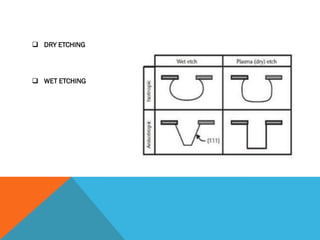
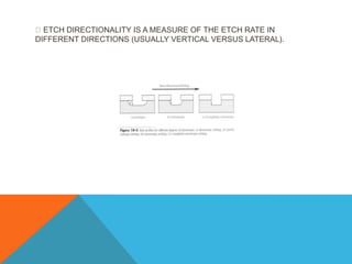
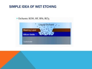
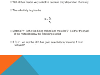
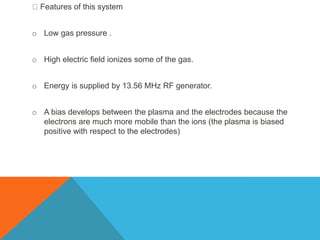
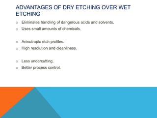
Etching
In order to form a functional MEMS structure on a substrate, it is necessary to etch the thin films previously deposited and/or the substrate itself. In general, there are two classes of etching processes:
Wet etching where the material is dissolved when immersed in a chemical solution
Dry etching where the material is sputtered or dissolved using reactive ions or a vapour phase etchant
Ion implantation is used in semiconductor device fabrication and in metal finishing, as well as in material science research.
it is a low temperature process that includes the acceleration of ions of a particular element towards a target, altering the chemical and physical properties of the target.
Different types of Nanolithography technique.
Types: Electron beam lithography, Photolithography, electron-beam writing, ion- lithography, X-ray lithography, and related images, concepts and graphical views.
I hope this presentation helpful for you.
https://www.linkedin.com/in/preeti-choudhary-266414182/
https://www.instagram.com/chaudharypreeti1997/
https://www.facebook.com/profile.php?id=100013419194533
https://twitter.com/preetic27018281
Please like, share, comment and follow.
stay connected
If any query then contact:
chaudharypreeti1997@gmail.com
Thanking-You
Preeti Choudhary
Discusses about photolithography, mask design, wet and dry bulk etching, bonding, thin film deposition and removal, metallization, sacrificial process and other inorganic processes.
Discusses about biomedical microdevices, systems and its various applications such as miniaturized systems including microelectronics, MEMS, microfluidics and nanosystmes measured in microns and nanometers.
Surface Chemistry and its impacts on chemical and electronic industryKramikauniyal
The content thoroughly explains about the processes and phenomenon that occur and are related to the surfaces of substances and how are they so impactful in chemical and electronic industry.
Semiconductor device fabrication is the process used to create the integrated circuits that are present in everyday electrical and electronic devices. It is a multiple-step sequence of photo lithographic and chemical processing steps during which electronic circuits are gradually created on a wafer made of pure semiconducting material. Silicon is almost always used, but various compound semiconductors are used for specialized applications.
Introduction
Invention of Chromatography
Chromatography
Paper Chromatography
Thin Layer Chromatography (TLC)
Liquid Chromatography (LC)
High Pressure Liquid Chromatography (HPLC)
Ion Chromatography
Gas Chromatography (GC)
Applications of chromatography
Conclusion
Design And Development of Hybrid Solar Dryers For Domestic Applicationssangeetkhule
INTRODUCTION
COMMERCIAL ASPECT
LITERATURE REVIEW
OUTCOME OF LITERATURE REVIEW
METHODOLOGY
DESIGN
CAD MODEL & SIMULATION
CONCLUSION
REFERENCES
Solar energy is a primary renewable energy source with the potential to meet
several challenges faced by humankind. Solar technologies convert sunlight into
electrical energy either through photovoltaic (PV) panels or through mirrors that
concentrate solar radiation. There are two basic mechanisms involved in the drying
process of solar drying; are: The migration of moisture from the interior of the
substance to be dried, and the second is the evaporation of moisture from the surface to
the surrounding air. The solar drying system utilizes the solar energy to heat air and to
dry any food substance which is loaded, which is not only beneficial but also it reduces
wastage of agricultural products and helps in the preservation of agricultural products,
but it also makes transportation of such dried product quickly and promotes the health
and welfare of the people. So, the development of a hybrid solar-energy dryer using a
photovoltaic (PV) solar panel to power the heating element coil and charge the battery,
which had a storage energy system, was developed and constructed with readily
available materials market was proposed.
This report presents the basics of the solar dryer, and the Literature review
contains recent innovative techniques used for developments of different types like
direct, indirect, mixed-mode, and hybrid solar dryers are discussed from the duration of
the previous two to three decades. Also, a comprehensive report of the fundamental
principles governing the drying process with the classification of the practically realized
various designs and selection of solar dryers for drying agricultural and marine products
has been presented.
The dryer comprises a solar collector (air heater) with the baffles and a solar
drying chamber containing a rack of four net trays, both being assimilated together. The
air allowed in through the air inlet is heated up in the solar collector chamber andchannelled through the drying chamber, where it is utilized in drying (removing the
moisture content from the food substances or agricultural product loaded in it). Locally
materials were used for the construction are wood, glass, aluminium metal sheet, PV,
and net for the trays.
The hybrid solar dryer discussed in the papers in the literature review is a
prominent practical technology that can dry various crops under all weather conditions.
Temperatures in the drying cabinet can be expected to range between 40 to 70ºC.
Compared to traditional drying, the hybrid dryer produces a better quality product and
can reduce the drying time by up to 50 to 70 %.
DESIGN AND DEVELOPMENT OF HYBRID SOLAR DRYER FOR DOMESTIC APPLICATIONSsangeetkhule
Introduction
Role of The Sun
Importance of Renewable Energy Sources
Solar Drying
Basics of Solar Energy
Working of Solar Cell
Basics of Solar Thermal Conversions
Outline of Thesis
Solar Dryer
Basics of Solar Dryers
Need For Dryers
Various Methods of Drying
Basics of Solar Drying Technique
Difference Between OSD & Solar Drying
Various Types of Solar Dryers
Working Consist of Hybrid Solar Dryer
Advantages & Reasons For Limited Use In India
Applications of Solar Dryers
Literature Review
Direct Solar Dryer
Indirect Solar Dryer
Mixed Mode Solar Dryer
Hybrid Solar Dryer
Conclusions
The outcome of Literature Review
Selection of Food Products
Methodology And Design Criterion
Methodology
Design Criterion
Selection of Solar Dryer Type
Design of Solar Dryer
Working of Model
Design Calculations
The Fan/Blower Design
Computer-Aided Design of Hybrid Solar Dryer
Solar Collector
Drying Chamber
Trays
Stand
Computational Analysis
Pre-Processor
PostProcessor
Economic Analysis
Economic Analysis of Dried Food Products
Bill
Actual Components For Fabricating
Commercial Solar Dryers
Other Locations
Conclusion And Recommendations
Conclusion
Recommendations
References
Power Requirements
Optimum Angle of Inclination
Solar Collector Area Calculations
Calculation of Components
Chapter 1 City of Residence
Chapter 2 Estimation of Available Solar Resources
Chapter 3 Site Survey
Chapter 4 Load Estimation
Chapter 5 Electricity Bill & Estimated Load
Chapter 6 Design of BOS & Market Survey
Chapter 7 Economical Analysis & Estimation of Payback Period
Chapter 8 Conclusion
Design Calculations for Solar Water Heating Systemsangeetkhule
Chapter 1 City of Residence
Chapter 2 Estimation of Available Solar Resources
Chapter 3 Site Survey
Chapter 4 Load Estimation
Chapter 5 Estimation of Required Absorber Area
Chapter 6 Market Survey & Estimation of No. of Tubes for ETC
Chapter 7 Economical Analysis & Estimation of Payback Period
Chapter 8 Conclusion
OPTICAL MICROSCOPY AND COORDINATE MEASURING MACHINE sangeetkhule
Introduction
Working principle
Classification
Construction and working
Different types of an optical scope
Process capabilities and analysis
Testing
Process parameters
Components and machine structure
Confocal laser scanning microscopy
Microscopic
Advantages
Applications
Advancement in CMM
Machine characteristics
Process parameters of CMM
Animation video
Research papers
Bar graphs and tables
Conclusion
References
THE GREEN BUILDING
INTRODUCTION
HISTORY
COMPARISON
NEED FOR GREEN BUILDINGS IN INDIA
HOW TO MAKE OUR BUILDINGS GREEN?
STRATEGIES & TECHNOLOGY
BENEFITS & LIMITATIONS
FEATURES, MATERIALS & METHODS
CHARACTERISTICS OF A GREEN BUILDING
TYPES OF GREEN BUILDING
LEED RATING SYSTEM
SOME GREEN BUILDINGS IN INDIA
CONCLUSION
REFERENCES
Heat Transfer Applications
Heat transfer is a discipline of thermal engineering that concerns the generation, use, conversion, and exchange of thermal energy between physical systems. Heat transfer is classified into various mechanisms, such as thermal conduction, thermal convection, thermal radiation, and transfer of energy by phase changes.
Introduction
Applications
References
conclusion
A to D Convertors
work to convert analog (continuous, infinitely variable) signals to digital (discrete-time, discrete-amplitude) signals. In more practical terms, an ADC converts an analog input, such as a microphone collecting sound, into a digital signal.
Composite material
A composite material is a material that is produced from two or more constituent materials. These constituent materials have notably dissimilar chemical or physical properties and are merged to create a material with properties, unlike the individual elements.
INTRODUCTION
HISTORY OF COMPOSITE MATERIALS
COMPONENTS
NEED OF COMPOSITE MATERIALS
FABRICATION METHODS
PROPERTIES
CLASSIFICATION OF COMPOSITES
NATURAL FIBRES
APPLICATIONS
ARTIFICIALLY MADE COMPOSITES
PARTICLE REINFORCED COMPOSITES
FIBRE-REINFORCED COMPOSITES
STRUCTURAL COMPOSITES
REFERENCES
Active suspension system
An active suspension is a type of automotive suspension on a vehicle. It uses an onboard system to control the vertical movement of the vehicle's wheels relative to the chassis or vehicle body rather than the passive suspension provided by large springs where the movement is determined entirely by the road surface. So-called active suspensions are divided into two classes: real active suspensions, and adaptive or semi-active suspensions. While adaptive suspensions only very shock absorber firmness to match changing road or dynamic conditions, active suspensions use some type of actuator to raise and lower the chassis independently at each wheel.
Diamond Turn Machining
Diamond turning is turning using a cutting tool with a diamond tip. It is a process of mechanical machining of precision elements using lathes or derivative machine tools equipped with natural or synthetic diamond-tipped tool bits.
Introduction
Components and machine structure
Different types of equipment
Tooling specifications
Tolerance and aspect ratios
Working principle
Control systems and power requirement
Process parameters
Material to be machined
MRR and surface finish
Advantages and disadvantages
Applications
Advancement in DTM
Machine characteristics
Machine tool requirement
Bar graphs and tables
Conclusion
References
Animation video
Conventional Braking System
Introduction OfRegenerative Braking System
Necessity Of The System
Elements Of Regenerative Braking System
Different Types Of Regenerative Braking System
Advantages And Disadvantages
Research Papers
Conclusion
Future Scope
References
Regenerative Braking System
Regenerative braking is a way of taking the wasted energy from the process of slowing down a car and using it to recharge the car's batteries.
Introduction
Literature Review
Recent Research And
Development In Hess
Case Study
Regenerative Braking System In
Bus
Regenerative Braking
System In Railways
Conclusion
Future Scope
References
AUTOMATIC PORTABLE HAMMERING MACHINE
TITLE PAGE
CERTIFICATE
ACKNOWLEDGEMENT
ABSTRACT
LIST OF FIGURES
INTRODUCTION
LITERATURE REVIEW
INTRODUCTION
PROJECT METHODS AND COMPONENT DETAILS
DESIGN OF HAMMERING MACHINE
CONCLUSION AND DISCUSSION
FUTURE SCOPE
REFERENCES
CAD MODEL
AUTOMATIC PORTABLE HAMMERING MACHINE
TITLE PAGE
CERTIFICATE
ACKNOWLEDGEMENT
ABSTRACT
LIST OF FIGURES
INTRODUCTION
LITERATURE REVIEW
INTRODUCTION
PROJECT METHODS AND COMPONENT DETAILS
DESIGN OF HAMMERING MACHINE
CONCLUSION AND DISCUSSION
FUTURE SCOPE
REFERENCES
CAD MODEL
AFFORESTATION AND NATIONAL AFFORESTATION PROGRAMME AND ACT - 2016sangeetkhule
AFFORESTATION AND NATIONAL AFFORESTATION PROGRAMME AND ACT - 2016
Afforestation is a process where new forests are planted across land without trees. As a forest grows, it naturally removes CO2 from the atmosphere and stores it in its trees.
Student information management system project report ii.pdfKamal Acharya
Our project explains about the student management. This project mainly explains the various actions related to student details. This project shows some ease in adding, editing and deleting the student details. It also provides a less time consuming process for viewing, adding, editing and deleting the marks of the students.
Immunizing Image Classifiers Against Localized Adversary Attacksgerogepatton
This paper addresses the vulnerability of deep learning models, particularly convolutional neural networks
(CNN)s, to adversarial attacks and presents a proactive training technique designed to counter them. We
introduce a novel volumization algorithm, which transforms 2D images into 3D volumetric representations.
When combined with 3D convolution and deep curriculum learning optimization (CLO), itsignificantly improves
the immunity of models against localized universal attacks by up to 40%. We evaluate our proposed approach
using contemporary CNN architectures and the modified Canadian Institute for Advanced Research (CIFAR-10
and CIFAR-100) and ImageNet Large Scale Visual Recognition Challenge (ILSVRC12) datasets, showcasing
accuracy improvements over previous techniques. The results indicate that the combination of the volumetric
input and curriculum learning holds significant promise for mitigating adversarial attacks without necessitating
adversary training.
CFD Simulation of By-pass Flow in a HRSG module by R&R Consult.pptxR&R Consult
CFD analysis is incredibly effective at solving mysteries and improving the performance of complex systems!
Here's a great example: At a large natural gas-fired power plant, where they use waste heat to generate steam and energy, they were puzzled that their boiler wasn't producing as much steam as expected.
R&R and Tetra Engineering Group Inc. were asked to solve the issue with reduced steam production.
An inspection had shown that a significant amount of hot flue gas was bypassing the boiler tubes, where the heat was supposed to be transferred.
R&R Consult conducted a CFD analysis, which revealed that 6.3% of the flue gas was bypassing the boiler tubes without transferring heat. The analysis also showed that the flue gas was instead being directed along the sides of the boiler and between the modules that were supposed to capture the heat. This was the cause of the reduced performance.
Based on our results, Tetra Engineering installed covering plates to reduce the bypass flow. This improved the boiler's performance and increased electricity production.
It is always satisfying when we can help solve complex challenges like this. Do your systems also need a check-up or optimization? Give us a call!
Work done in cooperation with James Malloy and David Moelling from Tetra Engineering.
More examples of our work https://www.r-r-consult.dk/en/cases-en/
Industrial Training at Shahjalal Fertilizer Company Limited (SFCL)MdTanvirMahtab2
This presentation is about the working procedure of Shahjalal Fertilizer Company Limited (SFCL). A Govt. owned Company of Bangladesh Chemical Industries Corporation under Ministry of Industries.
About
Indigenized remote control interface card suitable for MAFI system CCR equipment. Compatible for IDM8000 CCR. Backplane mounted serial and TCP/Ethernet communication module for CCR remote access. IDM 8000 CCR remote control on serial and TCP protocol.
• Remote control: Parallel or serial interface.
• Compatible with MAFI CCR system.
• Compatible with IDM8000 CCR.
• Compatible with Backplane mount serial communication.
• Compatible with commercial and Defence aviation CCR system.
• Remote control system for accessing CCR and allied system over serial or TCP.
• Indigenized local Support/presence in India.
• Easy in configuration using DIP switches.
Technical Specifications
Indigenized remote control interface card suitable for MAFI system CCR equipment. Compatible for IDM8000 CCR. Backplane mounted serial and TCP/Ethernet communication module for CCR remote access. IDM 8000 CCR remote control on serial and TCP protocol.
Key Features
Indigenized remote control interface card suitable for MAFI system CCR equipment. Compatible for IDM8000 CCR. Backplane mounted serial and TCP/Ethernet communication module for CCR remote access. IDM 8000 CCR remote control on serial and TCP protocol.
• Remote control: Parallel or serial interface
• Compatible with MAFI CCR system
• Copatiable with IDM8000 CCR
• Compatible with Backplane mount serial communication.
• Compatible with commercial and Defence aviation CCR system.
• Remote control system for accessing CCR and allied system over serial or TCP.
• Indigenized local Support/presence in India.
Application
• Remote control: Parallel or serial interface.
• Compatible with MAFI CCR system.
• Compatible with IDM8000 CCR.
• Compatible with Backplane mount serial communication.
• Compatible with commercial and Defence aviation CCR system.
• Remote control system for accessing CCR and allied system over serial or TCP.
• Indigenized local Support/presence in India.
• Easy in configuration using DIP switches.
3. ETCHING
After a thin film is deposited, it is usually etched to remove unwanted
materials and leave only the desired pattern on the wafer.
The process is done many times.
In addition to deposited films, sometimes we also need to etch the Si wafer
to create trenches.
The masking layer may be photoresist, SiO2 or Si3N4.
The etch is usually done until another layer of a different material is reached.
ETCHING
6. INTRODUCTION
Etching can be done ―wet‖ or ―dry‖
Wet etching
o uses liquid etchants.
o Wafer is immersed in the liquid.
o Process is mostly chemical.
Wet etching is not used much in VLSI wafer fabrication.
7. Dry etching
o Uses gas phase etchants in a plasma.
o The process is a combination of chemical and physical action.
o Process is often called ―plasma etching‖.
This is the normal process used in most VLSI fabrication.
The ideal etch produces vertical sidewalls.
In reality, the etch occurs both vertically and laterally .
8. There is undercutting, non vertical sidewalls, and some etching of the
Si.
The photoresist may have rounded tops and non-vertical sidewalls.
The etch rate of the photoresist is not zero and the mask is etched to
some extent.
This leads to more undercutting.
Etch selectivity is the ratio of the etch rates of different materials in the
process.
9. Etch selectivity is the ratio of the etch rates of different materials in the
process.
If the etch rate of the mask and of the underlying substrate is near zero, and
the etch rate of the film is high, we get high selectivity.
This is the normally desired situation .
If the etch rate of the mask or the substrate is high, the selectivity is poor.
Selectivity of 25 – 50 are reasonable.
Materials usually have differing etch rates due to chemical processes rather
than physical processes.
10. ETCH DIRECTIONALITY IS A MEASURE OF THE ETCH RATE IN
DIFFERENT DIRECTIONS (USUALLY VERTICAL VERSUS LATERAL).
11. TYPES OF ETCHING
We consider two processes :-
o ―wet‖ etching
o ―dry‖ etching
Wet process is well-established, simple, and inexpensive.
The need for smaller feature sizes could only be met with plasma
etching.
Plasma etching is used almost exclusively today.
12. WET ETCHING
In wet process by immersing the wafer in these chemicals, exposed
areas could be etched and washed away.
For SiO2, HF was used.
Wet etches work through chemical processes to produce a water
soluble byproduct.
13. In some cases, the etch works by first oxidizing the surface and then
dissolving the oxide.
An etch for Si involves a mixture of nitric acid and HF.
The nitric acid (HNO3) decomposes to form nitrogen dioxide (NO2).
The SiO2 is removed by the previous reaction.
The overall reaction is
15. Buffers are often added to keep the etchants at maximum strength
over use and time
Ammonium fluoride (NH4F) is often used with HF to help prevent
depletion of the F ions
This is called Basic Oxide Etch (BOE) or Buffered HF (BHF)
The ammonium fluoride reduces the etch rate of photoresist and helps
eliminate the lifting of the resist during oxide etching
Acetic acid (CH3COOH) is often added to the nitric acid/HF Si etch to
limit the dissociation of the nitric acid
16. Wet etches can be very selective because they depend on chemistry
The selectivity is given by
Material ―1‖ is the film being etched and material‖2‖ is either the mask
or the material below the film being etched
If S>>1, we say the etch has good selectivity for material 1 over
material 2
17. Most wet etches etch isotropically.
The exception is an etch that depends on the crystallographic
orientation.
Example—some etches etch <111> Si slower than <100> Si.
Etch bias is the amount of undercutting of the mask.
If we assume that the selectivity for the oxide over both the mask and
the substrate is infinite, we can define the etch depth as ―d‖ and the
bias as ―b‖.
18. We often deliberately build in some over etching into the process.
This is to account for the fact that
o The films are not perfectly uniform
o The etch is not perfectly uniform
The over etch time is usually calculated from the known uncertainties
in film thickness and etch rates
It is important to be sure that no area is under-etched; we can tolerate
some over- etching
19. DRY ETCHING (PLASMA ETCHING)
Plasma etching has (for the most part) replaced wet etching
There are two reasons:
o Very reactive ion species are created in the plasma that give rise to
very active etching
o Plasma etching can be very anisotropic (because the electric field
directs the ions)
20. Plasma systems can be designed so that either reactive chemical
components dominate or ionic components dominate.
Often, systems that mix the two are used
o The etch rate of the mixed system may be much faster than the sum
of the individual etch rates.
A basic plasma system is shown in the next slide
21. DRY ETCHING MECHANISMS
The main species involved in etching are
o Reactive neutral chemical species
o Ions
The reactive neutral species (free radicals in many cases) are
primarily responsible for the chemical component
The ions are responsible for the physical component
The two can work independently or synergistically
23. If the area of the electrodes is the same (symmetric system) we get
the solid curve of 10-8.
The sheaths are the regions near each electrode where the voltage
drops occur (the dark regions of the plasma).
The sheaths form to slow down the electron loss so that it equals the
ion loss per RF cycle.
In this case, the average RF current is zero.
24. The heavy ions respond to the average voltage
The light electrons respond to the instantaneous voltage
The electrons cross the sheath only during a short period in the cycle
when the sheath thickness is minimum
During most of the cycle, most of the electrons are turned back at the
sheath edge
The sheaths are thus deficient in electrons
They are thus dark because of a lack of light- emitting electron-ion
collisions
25. DRY ETCHING
For etching photoresist, we use O2.
For other materials we use species containing halides such as Cl2, CF4, and
HBr.
Sometimes H2, O2, and Ar may be added.
The high-energy electrons cause a variety of reactions.
The plasma contains
o Free electrons
o Ionized molecules
o Neutral molecules
o Ionized fragments
o Free radicals
26. In CF4 plasmas, there are
o Free electrons
o CF4
o CF3
o CF3
+
o F
CF and F are free radicals and are very reactive
Typically, there will be 1015 /cc neutral species and 108-1012 /cc ions
and electrons
27. Features of this system
o Low gas pressure .
o High electric field ionizes some of the gas.
o Energy is supplied by 13.56 MHz RF generator.
o A bias develops between the plasma and the electrodes because the
electrons are much more mobile than the ions (the plasma is biased
positive with respect to the electrodes)
28. ADVANTAGES OF DRY ETCHING OVER WET
ETCHING
o Eliminates handling of dangerous acids and solvents.
o Uses small amounts of chemicals.
o Anisotropic etch profiles.
o High resolution and cleanliness.
o Less undercutting.
o Better process control.