Float Zone & Bridgman
Crystal Growth Techniques
Abu Syed Md. Jannatul Islam
Lecturer, Dept. of EEE, KUET, BD
1
Department of Electrical and Electronic Engineering
Khulna University of Engineering & Technology
Khulna-9203
2
Limitations of CZ Method
 The quartz crucible (SiO2) gradually dissolves and
releases large quantities of oxygen into the melt.
More than 99% of this is lost as SiO gas from the
molten surface, but the rest stays in the melt and can
dissolve into the single crystal silicon.
 Another impurity, however with smaller
concentrations, that is also introduced into the melt
by the production process itself is carbon. The silicon
monoxide evaporating from the melt surface interacts
with the hot graphite susceptor and forms carbon
monoxide that re-enters the melt.
 As the crystal is pulled from the melt, the impurity
concentration incorporated into the crystal (solid) is
usually different from the impurity concentration of
the melt (liquid) at the interface.
3
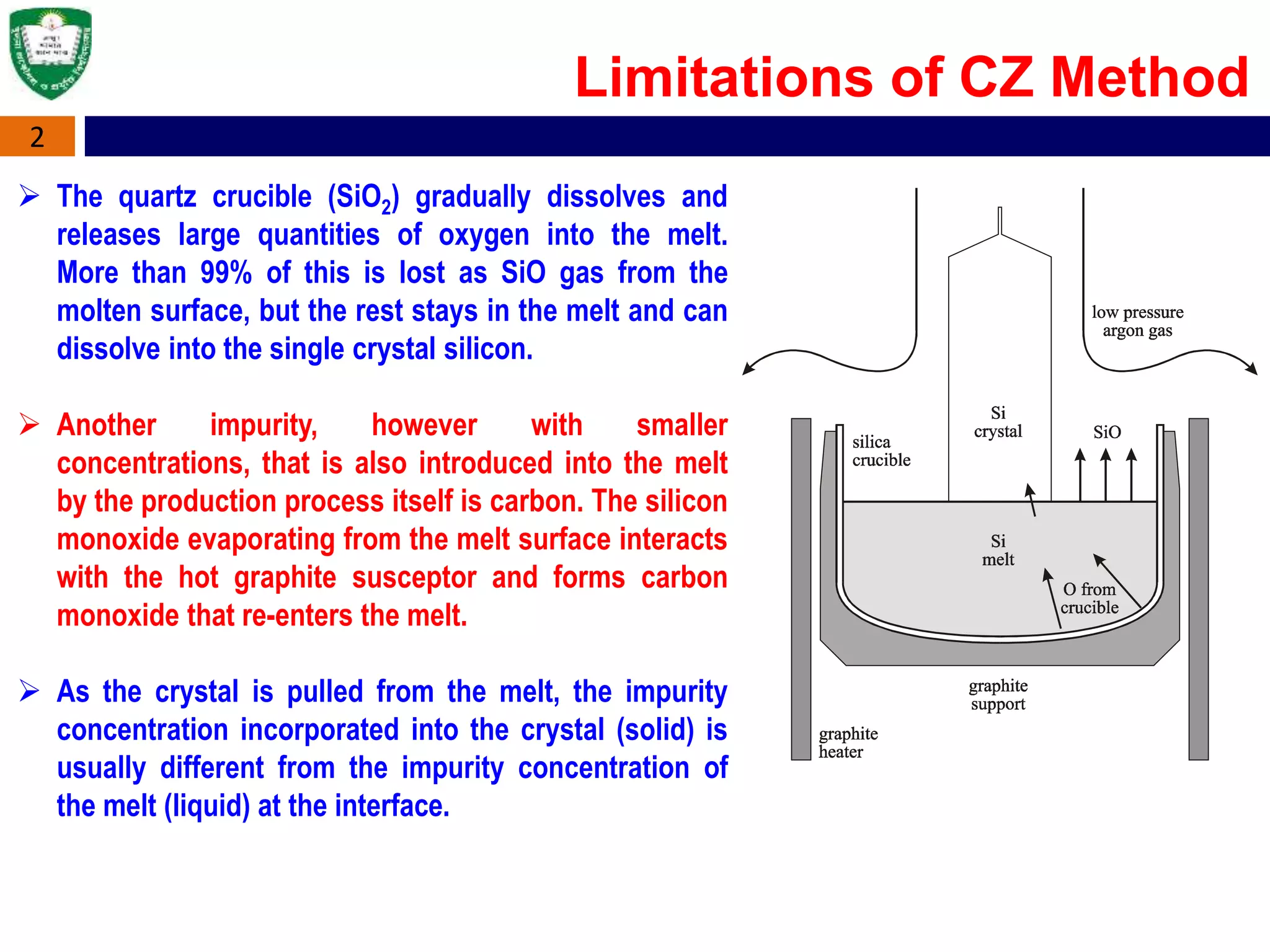
 Typical oxygen and carbon concentrations are [O] ≈ 5-10 10^17cm-3 and [C] ≈ 5 - 10
10^15cm-3, respectively, which lower the minority carrier diffusion length in the
finished silicon wafer.
 Low homogeneity of the axial and radial dopant concentration in the crystal caused
by oscillations in the melt during crystal growth. This makes it difficult to attain
high-ohmic CZ-wafers with a resistivity exceeding 100 Ohm cm.
 Furthermore the high oxygen concentration can lead to the formation of unwanted
electrically active defects. These are oxygen related thermal double donors (TDD)
and shallow thermal donors (STD) which can seriously change the resistivity of the
material.
Limitations of CZ Method
4
Advantages of CZ Method
 Oxygen has also good properties. Oxygen acts as a gettering agent for
trace metal impurities in the crystal and it can pin dislocations which
greatly strengthens the crystal.
 Oxygen precipitates in the wafer core suppress stacking faults, and
oxygen makes the Si more resistant to thermal stress during processing.
 The Czochralski-technique allows big crystal diameters and lower
production cost per wafer– compared to the float-zone technique
described in the following section.
 Better compatibility with advanced CMOS processes
 wafer made by CZ used in the electronics industry to make semiconductor
devices such as integrated circuits.
5
Oxygen Control Parameters
•Gas Flow
•Pressure
•Gas Flow Pattern
•Crucible Rotation
•Crystal Rotation
•Temperature Distribution
•Magnetic Field
A magnetic field (“Magnetic
Czochralski”, MCZ) can retard these
oscillations and improve the dopant
homogeneity in the ingot.
6
 The method is the same as the CZ method except that it is carried out within a strong
horizontal (HMCZ) or vertical (VMCZ) magnetic field.
 This serves to control the convection fluid flow, allowing e.g. with the HMCZ method to
minimise the mixing between the liquid in the center of the bath with that at the edge.
 This effectively creates a liquid silicon crucible around the central silicon bath, which can
trap much of the oxygen and slow its migration into the crystal.
 Compared to the standard CZ a lower oxygen concentration can be obtained and the
impurity distribution is more homogeneous.
 This method offers also the possibility to produce detector grade silicon with a high
oxygen concentration.
 Since the technology is still a very young one, it is hard to get such material with
reproducible impurity concentrations on a commercial basis. However, a first test material
of 4 KΩ.cm p-type with an oxygen concentration of 7-8 * l017 cm-3 and a carbon
concentration below 2xl016 cm-3 was obtained.
Magnetic Czochralski (MCZ)
7
Magnetic Czochralski (MCZ)
Magnetic field changes oxygen behavior
 Thicker laminar layer next to crucible
wall => slower oxygen dissolution
 Thicker laminar layer at gas interface
=> tendency to increase oxygen in
the melt
 Balance between these two effects
defines oxygen level
 Slow crucible erosion => long
crucible lifetime, low dopant
emission rate
 Price to pay: more difficult control of
radial variations! Both dopants and
oxygen
8
Magnetic Czochralski (MCZ)
MCZ Puller
9
 With the CCZ method a continuous supply of molten polycrystalline silicon is
achieved by using a double quartz crucible.
 In the first one the crystal is grown and in the second one, connected to the first one,
a reservoir of molten silicon is kept, that can be refilled by new polysilicon during the
growth process.
 This allows for larger crystal length and improves the throughput and operational
costs of the CZ grower.
 Furthermore the resulting single crystals have a uniform resistivity and oxygen
concentration and identical thermal history.
 In combination with the magnetic field method the Continuous Magnetic Field Applied
CZ technique (CMCZ) offers the possibility to grow long and large diameter CZ.
 However, silicon produced by this technology has so far not been used for radiation
damage experiments.
Continuous CZ (CCZ)
9
Continuous CZ (CCZ)
10
 The material requirements for the manufacturing of silicon particle detectors used
for high energy physics applications have to meet two basic demands:
 High resistivity (>1 Kohm/cm) and
 High minority carrier lifetime.
 Float Zone silicon is the best choice of material and is therefore exclusively used for
detector applications today.
 The main problem for the application as detector grade material arises from the
resistivity of CZ silicon. Due to contamination with boron, phosphorus and
aluminum from the dissolving quartz Crucible the highest commercially available
resistivity is about 100 Ohm cm for n-type and only slightly higher for p-type
material. Therefore standard CZ silicon is not suitable for detector production.
Requirements for Detectors
11
Float-Zone Crystal Growth
 No need to use quartz crucible as well as hot graphite container.
 The main advantage of the float-zone technique is the very low impurity
concentration in the silicon crystal as compared to CZ silicon(Carrier concentrations
down to 1011 atoms/cm3 have been achieved).
 The concentrations of light impurities, such as carbon and oxygen, are extremely
low. Another light impurity, nitrogen, helps to control micro-defects and also brings
about an improvement in mechanical strength of the wafers, and is now being
intentionally added during the growth stages.
 Additionally, the dopant concentration in the final crystal is rather homogeneous and
manageable which allows very high-ohmic (1-10 Kohm.cm) wafers as well as wafers
with a narrow specified electrical resistivity.
 Float zone silicon is typically used for power devices and detector applications. It is
good for solar cells, power electronic devices (thyristors and rectifiers) that use the
entire volume of the wafer not just a thin surface layer, etc
12
Float-Zone Crystal Growth
 Float-zone does not allow as large Si wafers as CZ does (200mm and 300mm) and
radial distribution of dopant in FZ wafer is not as uniform as in CZ wafer.
 The main technological disadvantage of the FZ method is the requirement for a
uniform, crack-free cylindrical feed rod. A cost premium (100% or more) is
associated with such poly rods.
 These crystals are more expensive and have very low oxygen and carbon and thus,
are not suitable for the majority of silicon IC technology.
At the present time, FZ Si is used for premium high-efficiency
cell applications and CZ Si is used for higher-volume, lower-cost
applications.
13
 Float-zone silicon is very pure silicon obtained
by vertical zone melting.
 The diameters of float-zone wafers are generally
not greater than 150 mm due to the surface
tension limitations during growth.
 A polycrystalline rod of ultra-pure electronic
grade silicon is passed through an RF heating
coil, which creates a localized molten zone from
which the crystal ingot grows.
 The RF coil and the melted zone move along the
entire ingot.
 A seed crystal is used at one end in order to
start the growth. The whole process is carried
out in an evacuated chamber or in an inert gas
purge.
Float-Zone Crystal Growth
14
Float-Zone Crystal Growth
 Since most impurities are less soluble in the crystal
than in the melted silicon, the molten zone carries
the impurities away with it. The impurities
concentrate near the end of the crystal where finally
they can simply be cut away (Dopants/impurities
prefer to stay in the liquid than in the solid).
 This procedure can be repeated one or more times
in order to further reduce the remaining impurity
concentration.
 Doping is realized during crystal growth by adding
dopant gases such as phosphine (PH3), arsine
(AsH3) or diborane (B2H6) to the inert
gas atmosphere.
 Specialized doping techniques like core doping, pill
doping, gas doping and neutron transmutation
doping are used to incorporate a uniform
concentration of impurity
A variety of heating systems can be
used for floating zone technique,
including induction coil, resistance
heater or more recently optical heating
system
15
• The rod/ polycrystalline silicon ingot is
clamped at each end, with one end in contact
with a single crystal seed.
• An RF heating coil induces eddy currents
(power I2R) in the silicon, heating it beyond its
melting point in the vicinity of the coil.
• The seed crystal touches the melt zone and is
pulled away, along with a solidifying Si boule
following the seed.
• The crystalline direction follows that of the
seed single crystal.
Melt is not held in a container, it is
“float”, thus the name “float zone”.
Float-Zone Crystal Growth
16
Doping in FZ Growth
Gas doping:
 Dopants are introduced in gaseous form during FZ growth.
 n-doping: PH3 (Phosphine), AsCl3
 p-doping: B2H6 (Diborane), BCl3
 Good uniformity along the length of the boule.
Pill doping:
 Drill a small hole in the top of the EGS rod, and insert the dopant.
 If the dopant has a small segregation coefficient, most of it will be carried with the
melt as it passes the length of the boule.
 Resulting in only a small non-uniformity.
 Ga and In doping work well this way.
RF heating Optical heating
17
Float-Zone Crystal Growth
Optical heating of the zone. Photograph of an optical FZ growth system.
18
Float-Zone Crystal Growth: Overview
19
 The Bridgman technique (also known as Bridgman-Stockbarger method) is one of the
oldest techniques used for growing crystals.
 The Bridgman–Stockbarger technique is named after Harvard physicist Percy Williams
Bridgman(1882-1961) and MIT physicist Donald C. Stockbarger (1895–1952).
 Similar to Czochralski technique, the Bridgman technique employs also a crystal
growth from melt.
 The Bridgman method is a popular way of producing certain semiconductor crystals
such as gallium arsenide, for which the Czochralski process is more difficult. The
process can reliably produce single crystal ingots, but does not necessarily result in
uniform properties through the crystal.
Bridgman Crystal Growth
20
Bridgman Crystal Growth
 In Bridgman technique, the crucible containing the molten material is translated
along the axis of a temperature gradient in a furnace, whereas in Stockbarger
technique, there is a high-temperature zone, an adiabatic loss zone and a low-
temperature zone.
 These two methods are very often not specifically differed in the terminology.
 The difference between the Bridgman technique and Stockbarger technique is
subtle:
 While both methods utilize a temperature gradient and a moving
crucible, the Bridgman technique utilizes the relatively uncontrolled
gradient produced at the exit of the furnace; The Stockbarger technique
introduces a baffle, or shelf, separating two coupled furnaces with
temperatures above and below the freezing point. Stockbarger's
modification of the Bridgman technique allows for better control over
the temperature gradient at the melt/crystal interface.
21
Bridgman Crystal Growth
The method involves heating polycrystalline material in a container above its melting
point and slowly cooling it from one end where a seed crystal is located. Single crystal
material is progressively formed along the length of the container. The process can be
carried out in a horizontal or vertical geometry.
22
 The principle of the Bridgman technique is
the directional solidification by translating
a melt from the hot zone to the cold zone
of the furnace.
 The bridgman furnace works with three
temperature zones. The upper zone with
temperatures above the melting point of
silicon. The lower zone with a temperature
below melting point and an adiabatic zone
as a baffel between the two.
 At first the polycrystalline material in the
crucible needs to be melted completely in
the hot zone and be brought into contact
with a seed at the bottom of the crucible.
 Part of the seed will be re-melted after the
contact with the melt. This provides a fresh
interface for the crystal growth.
Vertical Bridgman Crystal Growth
23
 The crucible is then translated slowly into the
cooler section of the furnace.
 The temperature at the bottom of the crucible
falls below the solidification temperature and
the crystal growth is initiated by the seed at
the melt-seed interface.
 After the whole crucible is translated through
the cold zone the entire melt converts to a
solid single-crystalline ingot.
 Due to a directed and controlled cooling
process of the cast, zones of aligned crystal
lattices are created.
 Merely 60% of the polycrystal silicon can be
processed to wafers for photovoltaics. The
rest gets lost in the sawing and cutting
process.
Vertical Bridgman Crystal Growth
Temperature ProfileVertical Bridgman Tube Furnace
24
Vertical Bridgman-Stockbarger Method
Schematics of the furnace and crucible used for GaAs growth.
TemperatureºC
25
Horizontal Bridgman-Stockbarger Method
26
 The vertical Bridgman technique enables the
growth of crystals in circular shape, unlike the D-
shaped ingots grown by horizontal Bridgman
technique.
 However, the crystals grown horizontally exhibit
high crystalline quality (e.g. low dislocation
density) since the crystal experiences lower
stress due to the free surface on the top of the
melt and is free to expand during the entire
growth process.
 Instead of moving the crucible, the furnace can
be translated from the seed end while the
crucible is kept stationary.
 In this manner a directional solidification can be
achieved, too.
 A further modification is the so called gradient
freezing technique, with which neither the
crucible nor the furnace needs to be translated.
Vertical vs Horizontal Method

Float Zone, Bridgman Techniques--ABU SYED KUET

  • 1.
    Float Zone &Bridgman Crystal Growth Techniques Abu Syed Md. Jannatul Islam Lecturer, Dept. of EEE, KUET, BD 1 Department of Electrical and Electronic Engineering Khulna University of Engineering & Technology Khulna-9203
  • 2.
    2 Limitations of CZMethod  The quartz crucible (SiO2) gradually dissolves and releases large quantities of oxygen into the melt. More than 99% of this is lost as SiO gas from the molten surface, but the rest stays in the melt and can dissolve into the single crystal silicon.  Another impurity, however with smaller concentrations, that is also introduced into the melt by the production process itself is carbon. The silicon monoxide evaporating from the melt surface interacts with the hot graphite susceptor and forms carbon monoxide that re-enters the melt.  As the crystal is pulled from the melt, the impurity concentration incorporated into the crystal (solid) is usually different from the impurity concentration of the melt (liquid) at the interface.
  • 3.
    3  Typical oxygenand carbon concentrations are [O] ≈ 5-10 10^17cm-3 and [C] ≈ 5 - 10 10^15cm-3, respectively, which lower the minority carrier diffusion length in the finished silicon wafer.  Low homogeneity of the axial and radial dopant concentration in the crystal caused by oscillations in the melt during crystal growth. This makes it difficult to attain high-ohmic CZ-wafers with a resistivity exceeding 100 Ohm cm.  Furthermore the high oxygen concentration can lead to the formation of unwanted electrically active defects. These are oxygen related thermal double donors (TDD) and shallow thermal donors (STD) which can seriously change the resistivity of the material. Limitations of CZ Method
  • 4.
    4 Advantages of CZMethod  Oxygen has also good properties. Oxygen acts as a gettering agent for trace metal impurities in the crystal and it can pin dislocations which greatly strengthens the crystal.  Oxygen precipitates in the wafer core suppress stacking faults, and oxygen makes the Si more resistant to thermal stress during processing.  The Czochralski-technique allows big crystal diameters and lower production cost per wafer– compared to the float-zone technique described in the following section.  Better compatibility with advanced CMOS processes  wafer made by CZ used in the electronics industry to make semiconductor devices such as integrated circuits.
  • 5.
    5 Oxygen Control Parameters •GasFlow •Pressure •Gas Flow Pattern •Crucible Rotation •Crystal Rotation •Temperature Distribution •Magnetic Field A magnetic field (“Magnetic Czochralski”, MCZ) can retard these oscillations and improve the dopant homogeneity in the ingot.
  • 6.
    6  The methodis the same as the CZ method except that it is carried out within a strong horizontal (HMCZ) or vertical (VMCZ) magnetic field.  This serves to control the convection fluid flow, allowing e.g. with the HMCZ method to minimise the mixing between the liquid in the center of the bath with that at the edge.  This effectively creates a liquid silicon crucible around the central silicon bath, which can trap much of the oxygen and slow its migration into the crystal.  Compared to the standard CZ a lower oxygen concentration can be obtained and the impurity distribution is more homogeneous.  This method offers also the possibility to produce detector grade silicon with a high oxygen concentration.  Since the technology is still a very young one, it is hard to get such material with reproducible impurity concentrations on a commercial basis. However, a first test material of 4 KΩ.cm p-type with an oxygen concentration of 7-8 * l017 cm-3 and a carbon concentration below 2xl016 cm-3 was obtained. Magnetic Czochralski (MCZ)
  • 7.
    7 Magnetic Czochralski (MCZ) Magneticfield changes oxygen behavior  Thicker laminar layer next to crucible wall => slower oxygen dissolution  Thicker laminar layer at gas interface => tendency to increase oxygen in the melt  Balance between these two effects defines oxygen level  Slow crucible erosion => long crucible lifetime, low dopant emission rate  Price to pay: more difficult control of radial variations! Both dopants and oxygen
  • 8.
  • 9.
    9  With theCCZ method a continuous supply of molten polycrystalline silicon is achieved by using a double quartz crucible.  In the first one the crystal is grown and in the second one, connected to the first one, a reservoir of molten silicon is kept, that can be refilled by new polysilicon during the growth process.  This allows for larger crystal length and improves the throughput and operational costs of the CZ grower.  Furthermore the resulting single crystals have a uniform resistivity and oxygen concentration and identical thermal history.  In combination with the magnetic field method the Continuous Magnetic Field Applied CZ technique (CMCZ) offers the possibility to grow long and large diameter CZ.  However, silicon produced by this technology has so far not been used for radiation damage experiments. Continuous CZ (CCZ)
  • 10.
  • 11.
    10  The materialrequirements for the manufacturing of silicon particle detectors used for high energy physics applications have to meet two basic demands:  High resistivity (>1 Kohm/cm) and  High minority carrier lifetime.  Float Zone silicon is the best choice of material and is therefore exclusively used for detector applications today.  The main problem for the application as detector grade material arises from the resistivity of CZ silicon. Due to contamination with boron, phosphorus and aluminum from the dissolving quartz Crucible the highest commercially available resistivity is about 100 Ohm cm for n-type and only slightly higher for p-type material. Therefore standard CZ silicon is not suitable for detector production. Requirements for Detectors
  • 12.
    11 Float-Zone Crystal Growth No need to use quartz crucible as well as hot graphite container.  The main advantage of the float-zone technique is the very low impurity concentration in the silicon crystal as compared to CZ silicon(Carrier concentrations down to 1011 atoms/cm3 have been achieved).  The concentrations of light impurities, such as carbon and oxygen, are extremely low. Another light impurity, nitrogen, helps to control micro-defects and also brings about an improvement in mechanical strength of the wafers, and is now being intentionally added during the growth stages.  Additionally, the dopant concentration in the final crystal is rather homogeneous and manageable which allows very high-ohmic (1-10 Kohm.cm) wafers as well as wafers with a narrow specified electrical resistivity.  Float zone silicon is typically used for power devices and detector applications. It is good for solar cells, power electronic devices (thyristors and rectifiers) that use the entire volume of the wafer not just a thin surface layer, etc
  • 13.
    12 Float-Zone Crystal Growth Float-zone does not allow as large Si wafers as CZ does (200mm and 300mm) and radial distribution of dopant in FZ wafer is not as uniform as in CZ wafer.  The main technological disadvantage of the FZ method is the requirement for a uniform, crack-free cylindrical feed rod. A cost premium (100% or more) is associated with such poly rods.  These crystals are more expensive and have very low oxygen and carbon and thus, are not suitable for the majority of silicon IC technology. At the present time, FZ Si is used for premium high-efficiency cell applications and CZ Si is used for higher-volume, lower-cost applications.
  • 14.
    13  Float-zone siliconis very pure silicon obtained by vertical zone melting.  The diameters of float-zone wafers are generally not greater than 150 mm due to the surface tension limitations during growth.  A polycrystalline rod of ultra-pure electronic grade silicon is passed through an RF heating coil, which creates a localized molten zone from which the crystal ingot grows.  The RF coil and the melted zone move along the entire ingot.  A seed crystal is used at one end in order to start the growth. The whole process is carried out in an evacuated chamber or in an inert gas purge. Float-Zone Crystal Growth
  • 15.
    14 Float-Zone Crystal Growth Since most impurities are less soluble in the crystal than in the melted silicon, the molten zone carries the impurities away with it. The impurities concentrate near the end of the crystal where finally they can simply be cut away (Dopants/impurities prefer to stay in the liquid than in the solid).  This procedure can be repeated one or more times in order to further reduce the remaining impurity concentration.  Doping is realized during crystal growth by adding dopant gases such as phosphine (PH3), arsine (AsH3) or diborane (B2H6) to the inert gas atmosphere.  Specialized doping techniques like core doping, pill doping, gas doping and neutron transmutation doping are used to incorporate a uniform concentration of impurity A variety of heating systems can be used for floating zone technique, including induction coil, resistance heater or more recently optical heating system
  • 16.
    15 • The rod/polycrystalline silicon ingot is clamped at each end, with one end in contact with a single crystal seed. • An RF heating coil induces eddy currents (power I2R) in the silicon, heating it beyond its melting point in the vicinity of the coil. • The seed crystal touches the melt zone and is pulled away, along with a solidifying Si boule following the seed. • The crystalline direction follows that of the seed single crystal. Melt is not held in a container, it is “float”, thus the name “float zone”. Float-Zone Crystal Growth
  • 17.
    16 Doping in FZGrowth Gas doping:  Dopants are introduced in gaseous form during FZ growth.  n-doping: PH3 (Phosphine), AsCl3  p-doping: B2H6 (Diborane), BCl3  Good uniformity along the length of the boule. Pill doping:  Drill a small hole in the top of the EGS rod, and insert the dopant.  If the dopant has a small segregation coefficient, most of it will be carried with the melt as it passes the length of the boule.  Resulting in only a small non-uniformity.  Ga and In doping work well this way.
  • 18.
    RF heating Opticalheating 17 Float-Zone Crystal Growth
  • 19.
    Optical heating ofthe zone. Photograph of an optical FZ growth system. 18 Float-Zone Crystal Growth: Overview
  • 20.
    19  The Bridgmantechnique (also known as Bridgman-Stockbarger method) is one of the oldest techniques used for growing crystals.  The Bridgman–Stockbarger technique is named after Harvard physicist Percy Williams Bridgman(1882-1961) and MIT physicist Donald C. Stockbarger (1895–1952).  Similar to Czochralski technique, the Bridgman technique employs also a crystal growth from melt.  The Bridgman method is a popular way of producing certain semiconductor crystals such as gallium arsenide, for which the Czochralski process is more difficult. The process can reliably produce single crystal ingots, but does not necessarily result in uniform properties through the crystal. Bridgman Crystal Growth
  • 21.
    20 Bridgman Crystal Growth In Bridgman technique, the crucible containing the molten material is translated along the axis of a temperature gradient in a furnace, whereas in Stockbarger technique, there is a high-temperature zone, an adiabatic loss zone and a low- temperature zone.  These two methods are very often not specifically differed in the terminology.  The difference between the Bridgman technique and Stockbarger technique is subtle:  While both methods utilize a temperature gradient and a moving crucible, the Bridgman technique utilizes the relatively uncontrolled gradient produced at the exit of the furnace; The Stockbarger technique introduces a baffle, or shelf, separating two coupled furnaces with temperatures above and below the freezing point. Stockbarger's modification of the Bridgman technique allows for better control over the temperature gradient at the melt/crystal interface.
  • 22.
    21 Bridgman Crystal Growth Themethod involves heating polycrystalline material in a container above its melting point and slowly cooling it from one end where a seed crystal is located. Single crystal material is progressively formed along the length of the container. The process can be carried out in a horizontal or vertical geometry.
  • 23.
    22  The principleof the Bridgman technique is the directional solidification by translating a melt from the hot zone to the cold zone of the furnace.  The bridgman furnace works with three temperature zones. The upper zone with temperatures above the melting point of silicon. The lower zone with a temperature below melting point and an adiabatic zone as a baffel between the two.  At first the polycrystalline material in the crucible needs to be melted completely in the hot zone and be brought into contact with a seed at the bottom of the crucible.  Part of the seed will be re-melted after the contact with the melt. This provides a fresh interface for the crystal growth. Vertical Bridgman Crystal Growth
  • 24.
    23  The crucibleis then translated slowly into the cooler section of the furnace.  The temperature at the bottom of the crucible falls below the solidification temperature and the crystal growth is initiated by the seed at the melt-seed interface.  After the whole crucible is translated through the cold zone the entire melt converts to a solid single-crystalline ingot.  Due to a directed and controlled cooling process of the cast, zones of aligned crystal lattices are created.  Merely 60% of the polycrystal silicon can be processed to wafers for photovoltaics. The rest gets lost in the sawing and cutting process. Vertical Bridgman Crystal Growth
  • 25.
    Temperature ProfileVertical BridgmanTube Furnace 24 Vertical Bridgman-Stockbarger Method
  • 26.
    Schematics of thefurnace and crucible used for GaAs growth. TemperatureºC 25 Horizontal Bridgman-Stockbarger Method
  • 27.
    26  The verticalBridgman technique enables the growth of crystals in circular shape, unlike the D- shaped ingots grown by horizontal Bridgman technique.  However, the crystals grown horizontally exhibit high crystalline quality (e.g. low dislocation density) since the crystal experiences lower stress due to the free surface on the top of the melt and is free to expand during the entire growth process.  Instead of moving the crucible, the furnace can be translated from the seed end while the crucible is kept stationary.  In this manner a directional solidification can be achieved, too.  A further modification is the so called gradient freezing technique, with which neither the crucible nor the furnace needs to be translated. Vertical vs Horizontal Method