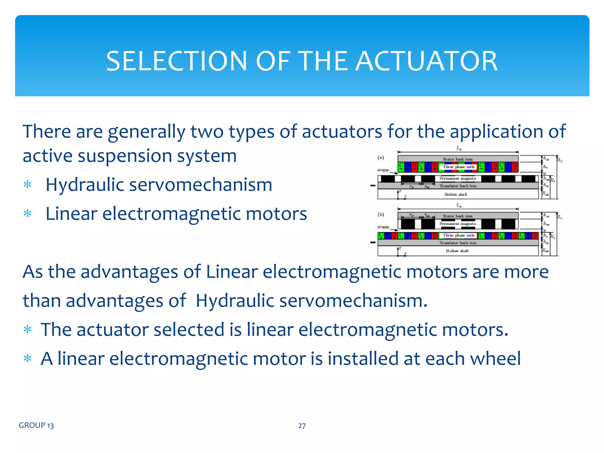
The document discusses the design and implementation of an active suspension system, focusing on the capabilities of an onboard system that adjusts vehicle wheel movements relative to the chassis. It explores various types of active suspensions, sensor technologies for monitoring, actuator selections, and concludes with a discussion on PID controllers for feedback control. The research emphasizes the advantages of linear electromagnetic motors over hydraulic systems in improving vehicle dynamics and passenger comfort.
![SUBJECT : MECHATRONICS SYSTEM
GROUP NO. 13
NAME ROLL NO.
GAURAV WADIBHASME [29]
SANGEET KHULE [60]
VAIBHAV PANDEY [74]
SHRI RAMDEOBABA COLLEGE OF ENGINEERING AND
MANAGEMENT
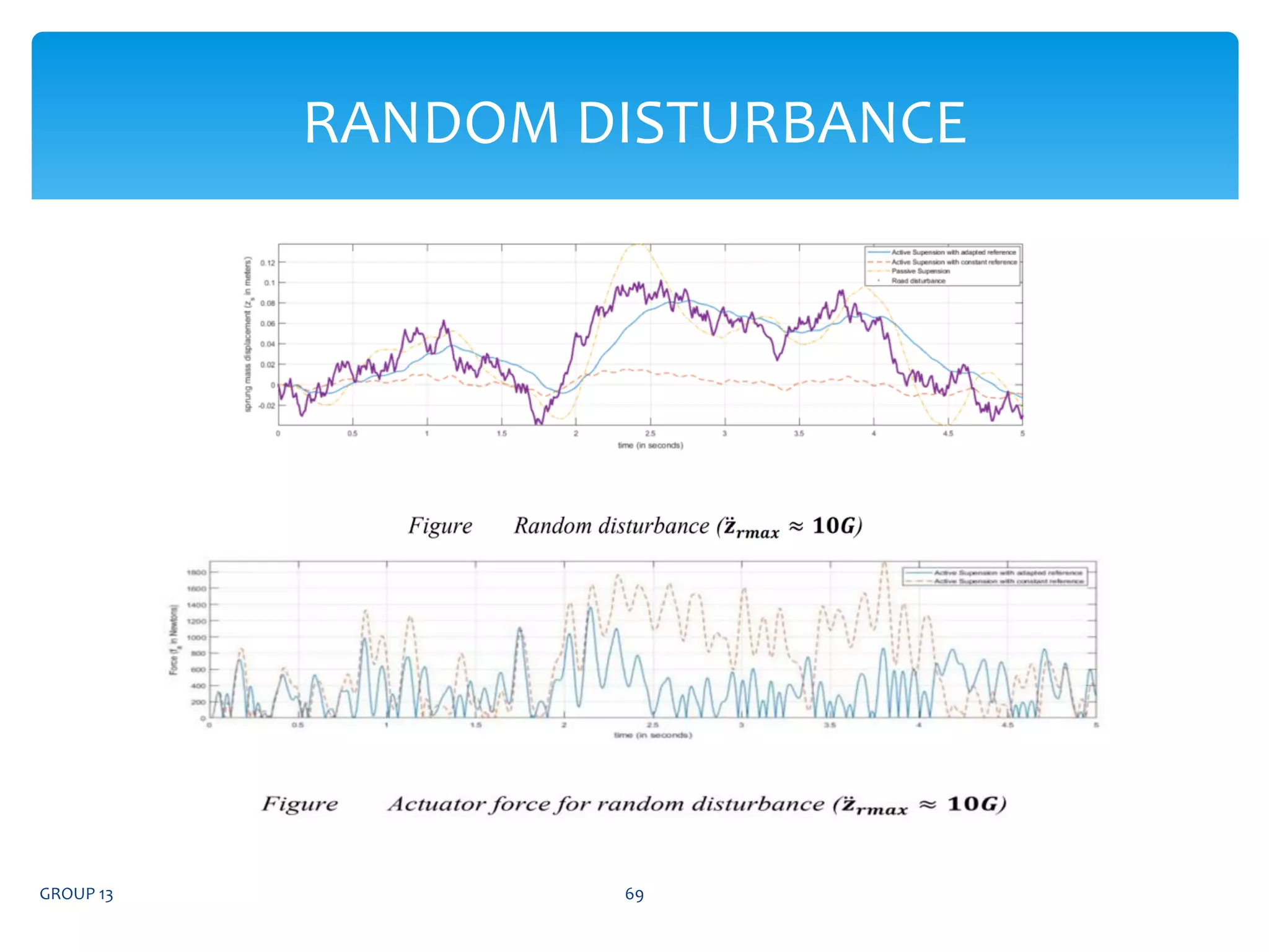
ACTIVE SUSPENSION SYSTEM
GROUP 13 1](https://image.slidesharecdn.com/groupno-210820232242/75/Active-suspension-system-1-2048.jpg)