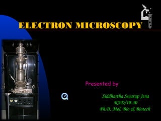
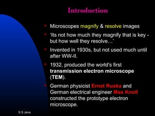
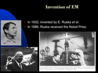
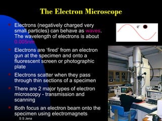
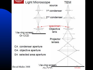
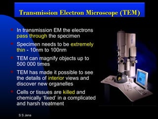
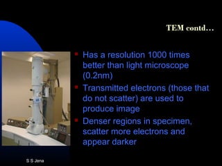
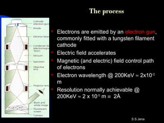
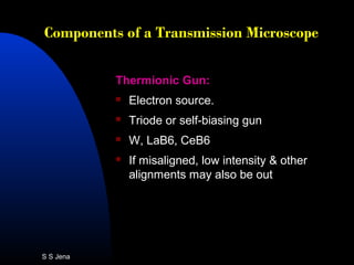
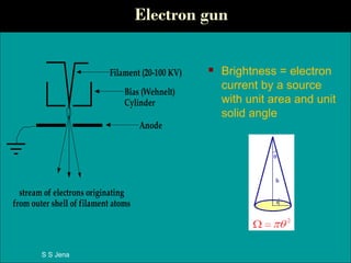
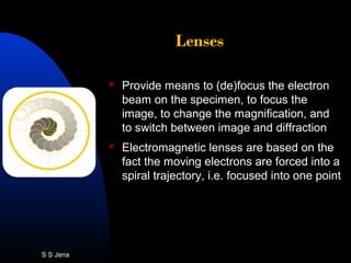
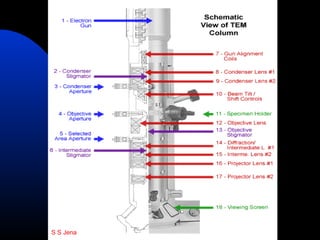
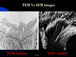
ELECTRON MICROSCOPYELECTRON MICROSCOPY
Presented by
sem.mov
Siddhartha Swarup Jena
RAD/10-30
Ph.D. Mol. Bio & Biotech
IntroductionIntroduction
 Microscopes magnify & resolve images
 ‘Its not how much they magnify that is key -
but how well they resolve…’
 Invented in 1930s, but not used much until
after WW-II.
 1932, produced the world's first
transmission electron microscope
(TEM).
 German physicist Ernst Ruska and
German electrical engineer Max Knoll
constructed the prototype electron
microscope.
S S Jena
Invention of EM
 In 1932, invented by E. Ruska et al.
 In 1986, Ruska received the Nobel Prize.
S S Jena
Contd…
 The transmission electron microscope
(TEM) was the first type of Electron
Microscope to be developed
 The first scanning electron microscope
(SEM) debuted in 1938 ( Von Ardenne)
with the first commercial instruments
around 1965.
 Its late development was due to the
electronics involved in "scanning" the
beam of electrons across the sample.
S S Jena
Imaging with a simple lens
α
α = semi-angular aperture
object
plane
image
plane
<<< conjugate planes of focus >>>
axis of lens
S S Jena
Focal length
f
f = focal length of lens
parallel
rays of light
axis
back focal plane of lens >>>
Distance between center of lens
and focal point is the focal length
S S Jena
Optics – A Simple Lens
S S Jena
Resolution
 The limit of resolution of a microscope is
the smallest distance between 2 points
that can be seen using a microscope
 This is a measure of the clarity of the
image
 As Magnification increases, resolution
decreases.
 Resolving power is inversely proportional
to the wavelength of the radiation it uses
S S Jena
Resolution
dmin =
0.61 λ
n sin α
n = refractive index
λ = wavelength
d
note: resolving power independent of lens properties
: for green (500nm) light dmin = c. 0.2 µm
S S Jena
The Light Microscope
 Series of lenses through which
ordinary white light can be
focused.
 Optical microscopes can not
resolve 2 points closer together
than about half (0.45) the
wavelength of the light used (450-
600nm).
 The total magnification is the
eyepiece magnification multiplied
by the objective magnification.
 The maximum magnification of a
light microscope is x1500 &
resolution up to 0.2 µm.
S S Jena
The Electron Microscope
 Electrons (negatively charged very
small particles) can behave as waves.
The wavelength of electrons is about
0.005nm
 Electrons are ‘fired’ from an electron
gun at the specimen and onto a
fluorescent screen or photographic
plate
 Electrons scatter when they pass
through thin sections of a specimen
 There are 2 major types of electron
microscopy - transmission and
scanning
 Both focus an electron beam onto the
specimen using electromagnets
S S Jena
Comparison of Optical and Electron MicroscopesComparison of Optical and Electron Microscopes
 Electron microscopes are operated in vacuum because
the mean free path of electrons in air is short – this mean
biological samples should not degas – they can either be
dehydrated or frozen
 Electron microscopes have higher resolution than optical
microscopes – atomic resolution is possible.
 Chemical imaging and spectroscopy – mapping π and σ
bonds at 1nm resolution can be done.
S S Jena
Why high vacuum ?
 Mean free path of electron is very
short in air
 Tungsten filaments burn out in air
 Columns must be kept dust free
 Achieved by two fold pumping:
Rotary (mechanical) pump +
Diffusion pump or + turbo pump
S S Jena

S S Jena
 In transmission EM the electrons
pass through the specimen
 Specimen needs to be extremely
thin - 10nm to 100nm
 TEM can magnify objects up to
500 000 times
 TEM has made it possible to see
the details of interior views and
discover new organelles
 Cells or tissues are killed and
chemically ‘fixed’ in a complicated
and harsh treatment
Transmission Electron Microscope (TEM)Transmission Electron Microscope (TEM)
S S Jena
TEM contd…
 Has a resolution 1000 times
better than light microscope
(0.2nm)
 Transmitted electrons (those that
do not scatter) are used to
produce image
 Denser regions in specimen,
scatter more electrons and
appear darker
S S Jena
The process
 Electrons are emitted by an electron gun,
commonly fitted with a tungsten filament
cathode
 Electric field accelerates
 Magnetic (and electric) field control path
of electrons
 Electron wavelength @ 200KeV ≈ 2x10-12
m
 Resolution normally achievable @
200KeV ≈ 2 x 10⁻¹⁰
m ≡ 2Å
S S Jena
Components of a Transmission MicroscopeComponents of a Transmission Microscope
Thermionic Gun:
 Electron source.
 Triode or self-biasing gun
 W, LaB6, CeB6
 If misaligned, low intensity & other
alignments may also be out
S S Jena
Electron gun
 Brightness = electron
current by a source
with unit area and unit
solid angle
Bias (Wehnelt)
Cylinder
Filament (20-100 KV)
Anode
stream of electrons originating
from outer shell of filament atoms
S S Jena
Lenses
 Provide means to (de)focus the electron
beam on the specimen, to focus the
image, to change the magnification, and
to switch between image and diffraction
 Electromagnetic lenses are based on the
fact the moving electrons are forced into a
spiral trajectory, i.e. focused into one point
S S Jena
The electromagnetic lens
 Works at fixed focal
distance and variable focal
length.
(like the human eye lens but
unlike light optics)
windings
soft iron
pole piece
windings
e-
electrons are charged, and are therefore
deflected when they cross a magnetic field
S S Jena
Lens system
a) Condenser lens:
 Uniformly illuminate the sample.
 Usually 2; C1 and C2 lens
 If misaligned, we will lose the beam when changing
magnification
b) Objective lens:
 Image sample – determines resolution.
 If misaligned, the image will be distorted, blurry.
c) Projector lens:
 magnifies image/ forms diffraction pattern – should not alter
resolution.
 If misaligned, the image will be distorted, diffraction pattern
may be blurry.
S S Jena
S S Jena
Mechanistic View of TEM
S S Jena
S S Jena
Sample preparation
1. Chemical fixation:
 Proteins with formaldehyde and glutaraldehyde and
lipids with osmium tetroxide.
2. Cryofixation:
 Freezing a specimen so rapidly, to liquid nitrogen or even
liquid helium temperatures, that the water forms vitreous
(non-crystalline) ice.
3. Dehydration:
 Freeze drying, or replacement of water with organic
solvents such as ethanol or acetone, followed by critical
point drying or infiltration with embedding resins.
S S Jena
Contd…
4. Embedding
 The tissue is passed through a 'transition solvent' such as
epoxy propane and then infiltrated with a resin such as
Araldite epoxy resin
 Tissues may also be embedded directly in water-miscible
acrylic resin
 After the resin has been polymerised (hardened) the
sample is thin sectioned (ultrathin sections) and stained - it
is then ready for viewing.
5. Sectioning
 These can be cut on an ultramicrotome with a diamond
knife to produce ultrathin slices about 60-90 nm thick.
 Disposable glass knives are also used because they can be
made in the lab and are much cheaper.
S S Jena
6. Staining
 Uses heavy metals such as lead,
uranium or tungsten to scatter
imaging electrons and thus give
contrast between different
structures, since many biological
materials are nearly "transparent"
to electrons (weak phase objects).
Contd…
S S Jena
Freeze-fracture or freeze-etch
 A preparation method particularly useful for examining
lipid membranes and their incorporated proteins in "face
on" view.
 The fresh tissue or cell suspension is frozen rapidly
(cryofixed), then fractured by simply breaking or by using
a microtome while maintained at liquid nitrogen
temperature.
 The cold fractured surface is then shadowed with
evaporated platinum or gold at an average angle of 45°
in a high vacuum evaporator.
 A second coat of carbon, evaporated perpendicular to
the average surface plane is often performed to improve
stability of the replica coating.
S S Jena
 The specimen is returned to room
temperature and pressure, then the
extremely fragile "pre-shadowed" metal
replica of the fracture surface is released
from the underlying biological material by
careful chemical digestion with acids,
hypochlorite solution or SDS detergent.
 The still-floating replica is thoroughly
washed from residual chemicals,
carefully fished up on fine grids, dried
then viewed in the TEM.
Contd…
S S Jena
TEM images
Transmission electron
micrograph of epithelial cells
from a rat small intestine.
Scale bar = 5 mm.
TEM view of a plant cell
S S Jena
TEM Limitations
 Specimen dead.
 Specimen preparation uses
extreme chemicals so artifacts
are always a concern.
S S Jena
 Live specimens possible. No
sectioning is required.
 Magnify objects up to two
million times.
 Lower magnifications than the
TEM.
 Resolving power is about
20nm
 In Scanning EM microscopes the electrons bounce off
the surface of the specimen
 Produce images with a three-dimensional appearance
 Allow detailed study of surfaces.
Scanning Electron Microscope (SEM)Scanning Electron Microscope (SEM)
S S Jena
S S Jena
Schematic view of
SEM
S S Jena
S S Jena
Sample preparation
 All water must be removed from the
samples because the water would
vaporize in the vacuum.
 All metals are conductive and require no
preparation before being used.
 All non-metals need to be made
conductive by covering the sample with a
thin layer of conductive material.
 This is done by using a device called a
"sputter coater.“
 E.g. gold coating
S S Jena
SEM images
Tumor spheroid
Insect head
S S Jena
TEM Vs SEM images
TEM- interior SEM- surfaceS S Jena
EM VariationsEM Variations
 High Voltage TEM
 Scanning tunneling microscope
 Scanning transmission electron
microscope (STEM)
 Scanning probe microscope
 Atomic force microscope
 Environmental scanning electron
microscope
 Elemental Composition SEM
S S Jena
ApplicationsApplications
 Morphology (imaging)
 Crystal structures (diffraction)
 Protein localization
 Electron & Cellular tomography
 Toxicology
 Biological production and viral load
monitoring
 Particle analysis
 Materials qualification
 Structural biology
 Virology
 Forensics
 Mining (mineral liberation analysis)
S S Jena
Disadvantages of EMDisadvantages of EM
 Expensive to build and maintain
 Requires extremely stable high-voltage supplies,
extremely stable currents to each electromagnetic
coil/lens, continuously-pumped high- or ultra-high-
vacuum systems, and a cooling water supply circulation
through the lenses and pumps.
 As they are very sensitive to vibration and external
magnetic fields, must be housed in stable buildings
(sometimes underground) with special services such as
magnetic field cancelling systems.
 The samples largely have to be viewed in vacuum
S S Jena
Light Vs Electron Microscopes
Feature Light Microscope Electron Microscope
Radiation used
Radiation source
Nature of lenses
Lenses used
Image seen
Radiation medium
Magnification
Limit of resolution
What it can show
S S Jena
….Thank You
S S Jena

Electrn microsopy @sid

  • 1.
    ELECTRON MICROSCOPYELECTRON MICROSCOPY Presentedby sem.mov Siddhartha Swarup Jena RAD/10-30 Ph.D. Mol. Bio & Biotech
  • 2.
    IntroductionIntroduction  Microscopes magnify& resolve images  ‘Its not how much they magnify that is key - but how well they resolve…’  Invented in 1930s, but not used much until after WW-II.  1932, produced the world's first transmission electron microscope (TEM).  German physicist Ernst Ruska and German electrical engineer Max Knoll constructed the prototype electron microscope. S S Jena
  • 3.
    Invention of EM In 1932, invented by E. Ruska et al.  In 1986, Ruska received the Nobel Prize. S S Jena
  • 4.
    Contd…  The transmissionelectron microscope (TEM) was the first type of Electron Microscope to be developed  The first scanning electron microscope (SEM) debuted in 1938 ( Von Ardenne) with the first commercial instruments around 1965.  Its late development was due to the electronics involved in "scanning" the beam of electrons across the sample. S S Jena
  • 5.
    Imaging with asimple lens α α = semi-angular aperture object plane image plane <<< conjugate planes of focus >>> axis of lens S S Jena
  • 6.
    Focal length f f =focal length of lens parallel rays of light axis back focal plane of lens >>> Distance between center of lens and focal point is the focal length S S Jena
  • 7.
    Optics – ASimple Lens S S Jena
  • 8.
    Resolution  The limitof resolution of a microscope is the smallest distance between 2 points that can be seen using a microscope  This is a measure of the clarity of the image  As Magnification increases, resolution decreases.  Resolving power is inversely proportional to the wavelength of the radiation it uses S S Jena
  • 9.
    Resolution dmin = 0.61 λ nsin α n = refractive index λ = wavelength d note: resolving power independent of lens properties : for green (500nm) light dmin = c. 0.2 µm S S Jena
  • 10.
    The Light Microscope Series of lenses through which ordinary white light can be focused.  Optical microscopes can not resolve 2 points closer together than about half (0.45) the wavelength of the light used (450- 600nm).  The total magnification is the eyepiece magnification multiplied by the objective magnification.  The maximum magnification of a light microscope is x1500 & resolution up to 0.2 µm. S S Jena
  • 11.
    The Electron Microscope Electrons (negatively charged very small particles) can behave as waves. The wavelength of electrons is about 0.005nm  Electrons are ‘fired’ from an electron gun at the specimen and onto a fluorescent screen or photographic plate  Electrons scatter when they pass through thin sections of a specimen  There are 2 major types of electron microscopy - transmission and scanning  Both focus an electron beam onto the specimen using electromagnets S S Jena
  • 12.
    Comparison of Opticaland Electron MicroscopesComparison of Optical and Electron Microscopes  Electron microscopes are operated in vacuum because the mean free path of electrons in air is short – this mean biological samples should not degas – they can either be dehydrated or frozen  Electron microscopes have higher resolution than optical microscopes – atomic resolution is possible.  Chemical imaging and spectroscopy – mapping π and σ bonds at 1nm resolution can be done. S S Jena
  • 13.
    Why high vacuum?  Mean free path of electron is very short in air  Tungsten filaments burn out in air  Columns must be kept dust free  Achieved by two fold pumping: Rotary (mechanical) pump + Diffusion pump or + turbo pump S S Jena
  • 14.
  • 15.
     In transmissionEM the electrons pass through the specimen  Specimen needs to be extremely thin - 10nm to 100nm  TEM can magnify objects up to 500 000 times  TEM has made it possible to see the details of interior views and discover new organelles  Cells or tissues are killed and chemically ‘fixed’ in a complicated and harsh treatment Transmission Electron Microscope (TEM)Transmission Electron Microscope (TEM) S S Jena
  • 16.
    TEM contd…  Hasa resolution 1000 times better than light microscope (0.2nm)  Transmitted electrons (those that do not scatter) are used to produce image  Denser regions in specimen, scatter more electrons and appear darker S S Jena
  • 17.
    The process  Electronsare emitted by an electron gun, commonly fitted with a tungsten filament cathode  Electric field accelerates  Magnetic (and electric) field control path of electrons  Electron wavelength @ 200KeV ≈ 2x10-12 m  Resolution normally achievable @ 200KeV ≈ 2 x 10⁻¹⁰ m ≡ 2Å S S Jena
  • 18.
    Components of aTransmission MicroscopeComponents of a Transmission Microscope Thermionic Gun:  Electron source.  Triode or self-biasing gun  W, LaB6, CeB6  If misaligned, low intensity & other alignments may also be out S S Jena
  • 19.
    Electron gun  Brightness= electron current by a source with unit area and unit solid angle Bias (Wehnelt) Cylinder Filament (20-100 KV) Anode stream of electrons originating from outer shell of filament atoms S S Jena
  • 20.
    Lenses  Provide meansto (de)focus the electron beam on the specimen, to focus the image, to change the magnification, and to switch between image and diffraction  Electromagnetic lenses are based on the fact the moving electrons are forced into a spiral trajectory, i.e. focused into one point S S Jena
  • 21.
    The electromagnetic lens Works at fixed focal distance and variable focal length. (like the human eye lens but unlike light optics) windings soft iron pole piece windings e- electrons are charged, and are therefore deflected when they cross a magnetic field S S Jena
  • 22.
    Lens system a) Condenserlens:  Uniformly illuminate the sample.  Usually 2; C1 and C2 lens  If misaligned, we will lose the beam when changing magnification b) Objective lens:  Image sample – determines resolution.  If misaligned, the image will be distorted, blurry. c) Projector lens:  magnifies image/ forms diffraction pattern – should not alter resolution.  If misaligned, the image will be distorted, diffraction pattern may be blurry. S S Jena
  • 23.
  • 24.
    Mechanistic View ofTEM S S Jena
  • 25.
  • 26.
    Sample preparation 1. Chemicalfixation:  Proteins with formaldehyde and glutaraldehyde and lipids with osmium tetroxide. 2. Cryofixation:  Freezing a specimen so rapidly, to liquid nitrogen or even liquid helium temperatures, that the water forms vitreous (non-crystalline) ice. 3. Dehydration:  Freeze drying, or replacement of water with organic solvents such as ethanol or acetone, followed by critical point drying or infiltration with embedding resins. S S Jena
  • 27.
    Contd… 4. Embedding  Thetissue is passed through a 'transition solvent' such as epoxy propane and then infiltrated with a resin such as Araldite epoxy resin  Tissues may also be embedded directly in water-miscible acrylic resin  After the resin has been polymerised (hardened) the sample is thin sectioned (ultrathin sections) and stained - it is then ready for viewing. 5. Sectioning  These can be cut on an ultramicrotome with a diamond knife to produce ultrathin slices about 60-90 nm thick.  Disposable glass knives are also used because they can be made in the lab and are much cheaper. S S Jena
  • 28.
    6. Staining  Usesheavy metals such as lead, uranium or tungsten to scatter imaging electrons and thus give contrast between different structures, since many biological materials are nearly "transparent" to electrons (weak phase objects). Contd… S S Jena
  • 29.
    Freeze-fracture or freeze-etch A preparation method particularly useful for examining lipid membranes and their incorporated proteins in "face on" view.  The fresh tissue or cell suspension is frozen rapidly (cryofixed), then fractured by simply breaking or by using a microtome while maintained at liquid nitrogen temperature.  The cold fractured surface is then shadowed with evaporated platinum or gold at an average angle of 45° in a high vacuum evaporator.  A second coat of carbon, evaporated perpendicular to the average surface plane is often performed to improve stability of the replica coating. S S Jena
  • 30.
     The specimenis returned to room temperature and pressure, then the extremely fragile "pre-shadowed" metal replica of the fracture surface is released from the underlying biological material by careful chemical digestion with acids, hypochlorite solution or SDS detergent.  The still-floating replica is thoroughly washed from residual chemicals, carefully fished up on fine grids, dried then viewed in the TEM. Contd… S S Jena
  • 31.
    TEM images Transmission electron micrographof epithelial cells from a rat small intestine. Scale bar = 5 mm. TEM view of a plant cell S S Jena
  • 32.
    TEM Limitations  Specimendead.  Specimen preparation uses extreme chemicals so artifacts are always a concern. S S Jena
  • 33.
     Live specimenspossible. No sectioning is required.  Magnify objects up to two million times.  Lower magnifications than the TEM.  Resolving power is about 20nm  In Scanning EM microscopes the electrons bounce off the surface of the specimen  Produce images with a three-dimensional appearance  Allow detailed study of surfaces. Scanning Electron Microscope (SEM)Scanning Electron Microscope (SEM) S S Jena
  • 34.
  • 35.
  • 36.
  • 37.
    Sample preparation  Allwater must be removed from the samples because the water would vaporize in the vacuum.  All metals are conductive and require no preparation before being used.  All non-metals need to be made conductive by covering the sample with a thin layer of conductive material.  This is done by using a device called a "sputter coater.“  E.g. gold coating S S Jena
  • 38.
  • 39.
    TEM Vs SEMimages TEM- interior SEM- surfaceS S Jena
  • 40.
    EM VariationsEM Variations High Voltage TEM  Scanning tunneling microscope  Scanning transmission electron microscope (STEM)  Scanning probe microscope  Atomic force microscope  Environmental scanning electron microscope  Elemental Composition SEM S S Jena
  • 41.
    ApplicationsApplications  Morphology (imaging) Crystal structures (diffraction)  Protein localization  Electron & Cellular tomography  Toxicology  Biological production and viral load monitoring  Particle analysis  Materials qualification  Structural biology  Virology  Forensics  Mining (mineral liberation analysis) S S Jena
  • 42.
    Disadvantages of EMDisadvantagesof EM  Expensive to build and maintain  Requires extremely stable high-voltage supplies, extremely stable currents to each electromagnetic coil/lens, continuously-pumped high- or ultra-high- vacuum systems, and a cooling water supply circulation through the lenses and pumps.  As they are very sensitive to vibration and external magnetic fields, must be housed in stable buildings (sometimes underground) with special services such as magnetic field cancelling systems.  The samples largely have to be viewed in vacuum S S Jena
  • 43.
    Light Vs ElectronMicroscopes Feature Light Microscope Electron Microscope Radiation used Radiation source Nature of lenses Lenses used Image seen Radiation medium Magnification Limit of resolution What it can show S S Jena
  • 44.