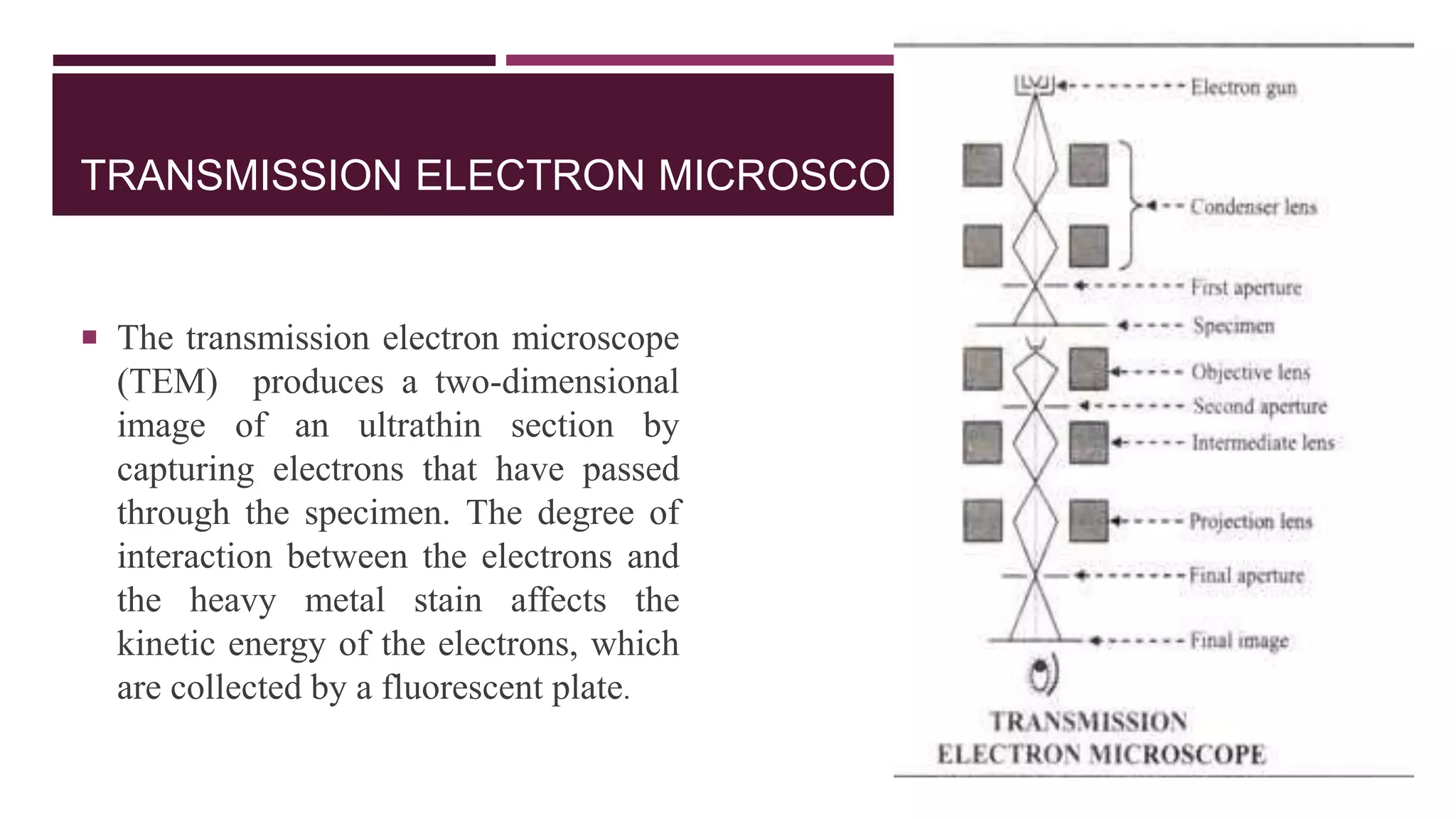
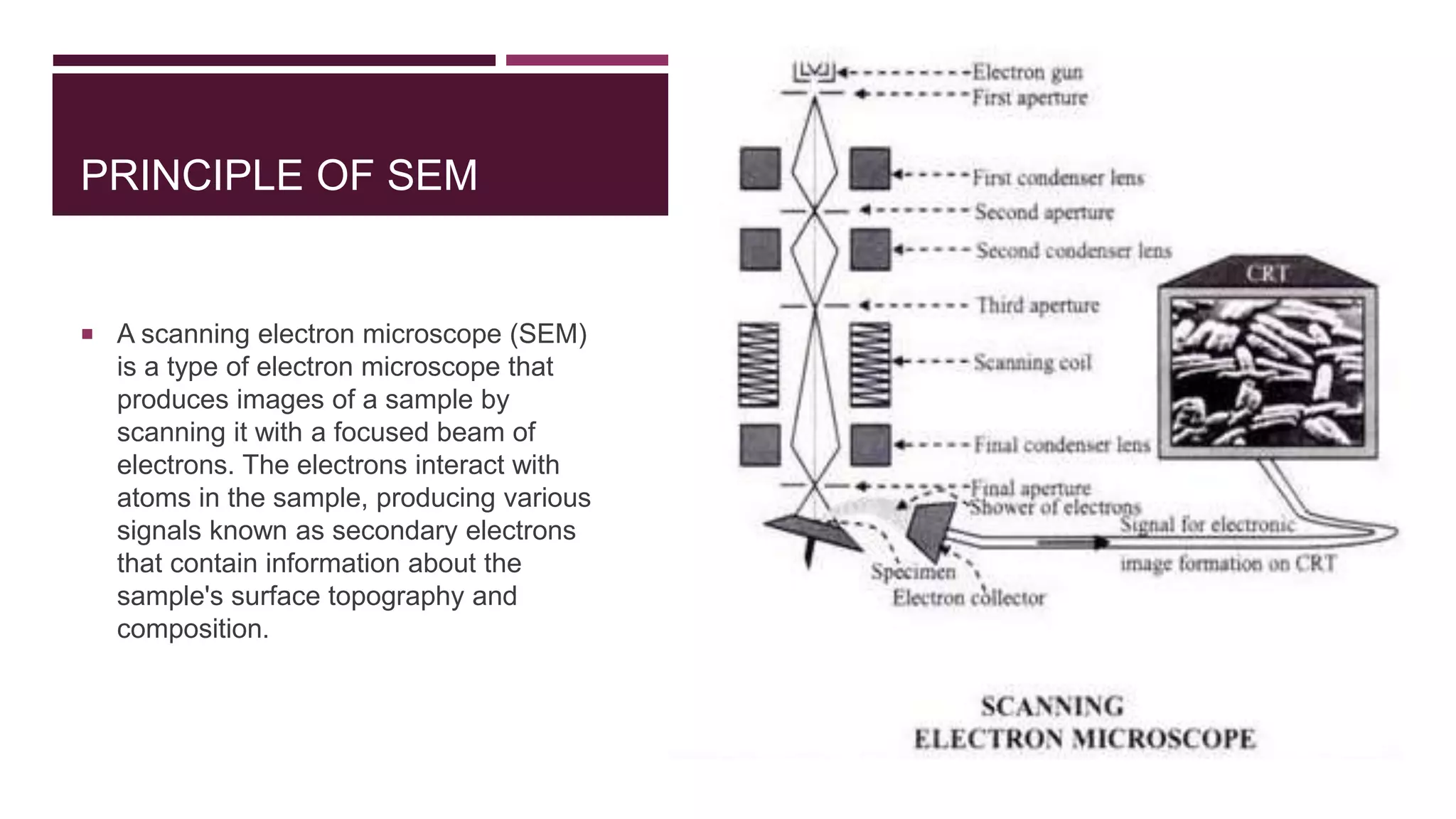
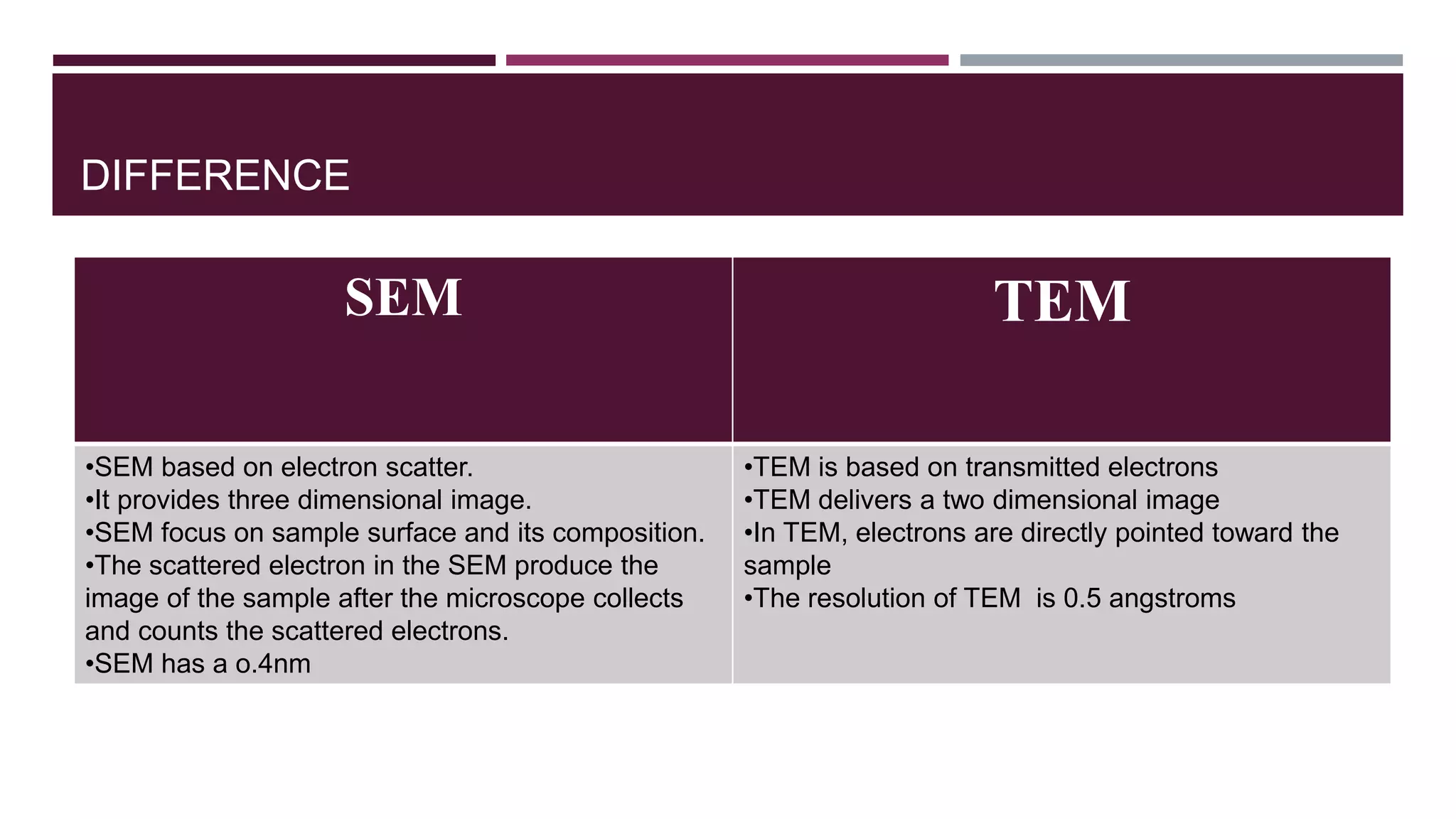
ELECTRON MICROSCOPE
INTRODUCTION
 The electron microscope is a type of microscope that uses a beam of electrons to
create an image of the specimen. It is capable of much higher magnifications and has
a greater resolving power than a light microscope, allowing it to see much smaller
objects in finer detail. They are large, expensive pieces of equipment, generally
standing alone in a small, specially designed room and requiring trained personnel to
operate them.
 An electron microscope can resolve objects as small as 0.001µ (=10 Å), as compared
to 0.2µ by a light microscope.
WORKING PRINCIPLE OF ELECTRON MICROSCOPE
 An electron microscope uses an ‘electron beam’ to produce the image of the object
and magnification is obtained by ‘electromagnetic fields’; unlike light or optical
microscopes, in which ‘light waves’ are used to produce the image and magnification
is obtained by a system of ‘optical lenses’
TYPES OF ELECTRON MICROSCOPE
 TRANSMISSION ELECTRON MICROSCOPE (TEM)
 SCANNING ELECTRON MICROSCOPE (SEM)
TRANSMISSION ELECTRON MICROSCOPE
 The transmission electron microscope
(TEM) produces a two-dimensional
image of an ultrathin section by
capturing electrons that have passed
through the specimen. The degree of
interaction between the electrons and
the heavy metal stain affects the
kinetic energy of the electrons, which
are collected by a fluorescent plate.
WORKING PRINCIPLE
 Illumination - Source is a beam of high velocity electrons accelerated under vacuum,
focused by condenser lens (electromagnetic bending of electron beam) onto specimen.
 Image formation - Loss and scattering of electrons by individual parts of the specimen.
Emergent electron beam is focused by objective lens. Final image forms on a
fluorescent screen for viewing.
 Image capture – on negative or by digital camera.
CONSTRUCTION
 ELECTRON SOURCE (GUN):-
The electron source consists of a cathode and an anode. The cathode is a
tungsten filament which emits electrons when being heated. A negative cap confines
the electrons into a loosely focused beam. The beam is then accelerated towards the
specimen by the positive anode.
 CONDENSER LENS:-
The stream of the electron from the electron gun is then focussed to a small,
thin, coherent beam by the use of condenser lenses. The first lens determines the spot
size the general size range of the final spot that strikes the sample. The second lens
actually changes the size of the spot on the sample.
 CONDENSER APERTURE:-
A condenser aperture is a thin disk or strip of metal with a small circular through-hole. It is used to
restrict the electron beams and filter out unwanted scattered electrons before image formation
 SAMPLE: -
The beam from the condenser aperture strikes the sample and the electron-sample interaction takes
place in three different ways. One is unscattered electrons(transmitted beam), elastically scattered
electrons (diffracted beam) and in elastically scattered electrons.
 OBJECTIVE LENS: -
The main function of the objective lens is to focuses the transmitted electron from the sample into an
image.
 OBJECTIVE APERTURE:-
Objective aperture enhances the contrast by blocking out high-angle diffracted electrons.
 PROJECTOR LENS:-
The projector lens are used to expand the beam onto the phosphor screen.
 SCREEN:-
Imaging systems in a TEM consists of a phosphor screen, which may be made of fine(10-100
micro meter) particulate zinc sulphide, for direct observation by the operator.
 IMAGE PATTERN:-
The image strikes the phosphor screen and light is generated, allowing the users to see the image.
SAMPLE PREPARATION
 Fixation: A process used to preserve the structure of freshly killed material in a state that most closely
resembles the structure and/or composition of the original living state. Osmium tetroxide has a very
high electron density so it is widely used in electron microscope. After fixation the sample is
dehydrated by exposuring into alcohol or acetone.
 Embedding : The sample are embedded in the infiltrating material such as epoxy plastic .
 Sectioning : The trimmed block containing the embedded samples are sectioned using a microtome.
 Mounting : The section are mounted on the copper grid that have coated with a thin film of carbon
which supports the section.
WORKING
 The electron beam is produced by an electron gun, commonly fitted with a tungsten filament cathode as the
electron source. The electron beam is accelerated by an anode typically at +100 ev (40 to 400 kev) with
respect to the cathode, focused by electrostatic and electromagnetic lenses, and transmitted through the
specimen that is in part transparent to electrons and in part scatters them out of the beam. When it emerges
from the specimen, the electron beam carries information about the structure of the specimen that is magnified
by the objective lens system of the microscope. The spatial variation in this information (the "image") may be
viewed by projecting the magnified electron image onto a fluorescent viewing screen coated with a phosphor
or scintillator material such as zinc sulfide. Alternatively, the image can be photographically recorded by
exposing a photographic film or plate directly to the electron beam, or a high-resolution phosphor may be
coupled by means of a lens optical system or a fibre optic light-guide to the sensor of a digital camera. The
APPLICATION OF TEM
 Material Sciences
• Morphology, structure, and local chemistry of metals
• Investigation of crystal structures, orientations and chemical compositions of phases, precipitates and
contaminants
 Medical and life Sciences
• To study the structure and composition of viruses (virology)
• To study the composition of cell
ADVANTAGE OF TEM
 TEMs offer the most powerful magnification, potentially over one million times or more
 TEMs provide information on element and compound structure images are high-quality and detailed
 TEMs are able to yield information of surface features, shape, size and structure .They are easy to
operate with proper training
LIMITATION
 Many materials require extensive sample preparation to produce a sample of 1μ which is time
consuming.
 The sample preparation may bring structural changes in the original structure.
 As the field of view is very small so the area or the region of the sample observed maynot represent the
whole.
 Biological samples may get damaged on prolonged exposure to electron beam.
SCANNING ELECTRON MICROSCOPE
 A scanning electron microscope is a type of electron microscope that images a sample
by scanning it with a high energy beam of electrons in a raster scan pattern.
PRINCIPLE OF SEM
 A scanning electron microscope (SEM)
is a type of electron microscope that
produces images of a sample by
scanning it with a focused beam of
electrons. The electrons interact with
atoms in the sample, producing various
signals known as secondary electrons
that contain information about the
sample's surface topography and
composition.
CONSTRUCTION
 Electron gun: This electron gun has a tungsten filament which functions as cathode. It emits electron
from its surface when it gets heated by passage of high voltage electricity.
 Condenser lens – there are 2 condenser placed just below the electron gun i.e. Primary condenser
lens and secondary condenser lens. It’s main function is to focus the electron beam to a narrower part.
 Objective aperature – it directs the narrowed electron beam which has the thickness of 20nm on to the
objective lens through the scanning coil.
 Scanning coil – The beam passes through pairs of scanning coils or pairs of deflector plates in the
electron column, typically in the final lens, which deflect the beam in the x and y axes so that it scans in
a raster fashion over a rectangular area of the sample surface.
 Objective lens – it focuses the scanning beam on the desired area of the specimen.
 The detectors - the electrons are detected by an ever hart thornley detector, which is a type of
scintillator-photomultiplier system. The secondary electrons are collected by a positively charged grid
arrangement. In modern SEM’s multi-electronic detectors are used to develop coloured image instead of
panchromatic images.
 Television picture tube – the secondary electron collected by thee positively charge grid is sent to the
television picture tube where the final image is formed
SAMPLE PREPARATION
 Cleaning the surface of specimen- the proper cleaning of the surface of the sample is important
because the surface can contain a variety of unwanted deposits such as dust ,silt , detritus or other
components, depending on the source of biological material and the experiment that may have been
conducted prior to SEM specimen preparation.
 Stabilizing the Specimen – Stabilization is typically done with fixatives. Fixation can be achieved , for
eg, by perfusion and micro injection , immersions or vapours using various fixatives including aldehydes,
osmium tetroxide, tannic acid, thiocarbohydrazide.
 Rinsing the specimen – After the fixation step , samples must be rinsed in order to remove the excess
fixative.
 Dehydrating the Specimen – The dehydration process of a biological sample needs to be done very
carefully. It is typically performed with either a graded series of acetone or ethanol
 Drying the Specimen – The SEM (like the TEM) operates with a vacuum . Thus , specimens must be
dry or the sample will be destroyed in the electron microscope chamber.
 Mounting the specimen – After the sample has been cleaned , fixed , rinsed , dehydrated and dried
using an appropriate protocol , specimens must be mounted on a holder that can be inserted into the
scanning electron microscope. Samples are typically mounted on metallic (aluminum) stubs using a
double sticky tape
 Coating the specimen – The idea of coating the specimen is to increase its conductivity in the
scanning electron microscope and to prevent the build up of high voltage charges on the specimen by
conducting the charge to ground. Typically , specimens are coated with a thin layer of approx. 20-30nm
of a conducting metal , e.g. GOLD , PLATINUM etc…
MECHANISM
 An electron beam is emitted from an electron gun fitted with a tungsten filament cathode. The electron
beam, which typically has an energy ranging from 0.2 kev to 40 kev, is focused by one or two condenser
lenses to a spot of sample. The beam passes through pairs of scanning coils or pairs of deflector plates
in the electron column. In the final lens, the deflected beam in the x and y axis so that it can be scanned
in a raster fashion over a rectangular area of the sample surface. When the primary electron beam
interacts with the sample, the electrons lose energy by repeated random scattering and absorption
within a teardrop-shaped volume of the specimen known as the interaction volume, the interaction
volume depends on the electron's landing energy, the atomic number of the specimen and the
specimen's density. The energy exchange between the electron beam and the sample results in the
reflection of high-energy electrons by elastic scattering, each of which can be detected by specialized
detectors. The beam current absorbed by the specimen can also be detected and used to
APPLICATION
 Semiconductor industry
• Failure Analysis of Integrated Circuits
• Advanced Packaging: Wire Bonding
• Circuit Edits
• Micro-Electro-Mechanical systems
 Geology and Earth sciences.
• metamorphic petrology and mineralogy
• Ore processing
• Oil & Gas
• Palaeontology
Biotechnology/ life sciences
• cell morphology,
• Development of biocompatible materials,
• tissue engineering research,
• microbiology
ADVANTAGE
 Its basically used for biological samples
 It can scan the processes occurring on surface and tells about topography and composition.
 Enable us to view without thinning dehydrating fixing the sample
 Can scan bulk samples up to 2-3 cm which can not be examined by TEM.
 View obtained is in 3D.
 ESEM produce image of Wet, gas &Vacuumed Samples and biological samples
DISADVANTAGE
 SEM’s are expensive, large and must be housed in an area free of any possible electric, magnetic or
vibration interference.
 • Maintenance involves keeping a steady voltage, currents to electromagnetic coils and circulation of
cool water.
 • Special training is required to operate an SEM as well as prepare samples.
 • The preparation of samples can result in artifacts. The negative impact can be minimized with
knowledgeable experience researchers being able to identify artifacts from actual data as well as
preparation skill. There is no absolute way to eliminate or identify all potential artifacts.
DIFFERENCE
SEM TEM
•SEM based on electron scatter.
•It provides three dimensional image.
•SEM focus on sample surface and its composition.
•The scattered electron in the SEM produce the
image of the sample after the microscope collects
and counts the scattered electrons.
•SEM has a o.4nm
•TEM is based on transmitted electrons
•TEM delivers a two dimensional image
•In TEM, electrons are directly pointed toward the
sample
•The resolution of TEM is 0.5 angstroms
Electron microscope

Electron microscope

  • 1.
  • 2.
    INTRODUCTION  The electronmicroscope is a type of microscope that uses a beam of electrons to create an image of the specimen. It is capable of much higher magnifications and has a greater resolving power than a light microscope, allowing it to see much smaller objects in finer detail. They are large, expensive pieces of equipment, generally standing alone in a small, specially designed room and requiring trained personnel to operate them.  An electron microscope can resolve objects as small as 0.001µ (=10 Å), as compared to 0.2µ by a light microscope.
  • 3.
    WORKING PRINCIPLE OFELECTRON MICROSCOPE  An electron microscope uses an ‘electron beam’ to produce the image of the object and magnification is obtained by ‘electromagnetic fields’; unlike light or optical microscopes, in which ‘light waves’ are used to produce the image and magnification is obtained by a system of ‘optical lenses’
  • 4.
    TYPES OF ELECTRONMICROSCOPE  TRANSMISSION ELECTRON MICROSCOPE (TEM)  SCANNING ELECTRON MICROSCOPE (SEM)
  • 5.
    TRANSMISSION ELECTRON MICROSCOPE The transmission electron microscope (TEM) produces a two-dimensional image of an ultrathin section by capturing electrons that have passed through the specimen. The degree of interaction between the electrons and the heavy metal stain affects the kinetic energy of the electrons, which are collected by a fluorescent plate.
  • 6.
    WORKING PRINCIPLE  Illumination- Source is a beam of high velocity electrons accelerated under vacuum, focused by condenser lens (electromagnetic bending of electron beam) onto specimen.  Image formation - Loss and scattering of electrons by individual parts of the specimen. Emergent electron beam is focused by objective lens. Final image forms on a fluorescent screen for viewing.  Image capture – on negative or by digital camera.
  • 7.
    CONSTRUCTION  ELECTRON SOURCE(GUN):- The electron source consists of a cathode and an anode. The cathode is a tungsten filament which emits electrons when being heated. A negative cap confines the electrons into a loosely focused beam. The beam is then accelerated towards the specimen by the positive anode.  CONDENSER LENS:- The stream of the electron from the electron gun is then focussed to a small, thin, coherent beam by the use of condenser lenses. The first lens determines the spot size the general size range of the final spot that strikes the sample. The second lens actually changes the size of the spot on the sample.
  • 8.
     CONDENSER APERTURE:- Acondenser aperture is a thin disk or strip of metal with a small circular through-hole. It is used to restrict the electron beams and filter out unwanted scattered electrons before image formation  SAMPLE: - The beam from the condenser aperture strikes the sample and the electron-sample interaction takes place in three different ways. One is unscattered electrons(transmitted beam), elastically scattered electrons (diffracted beam) and in elastically scattered electrons.  OBJECTIVE LENS: - The main function of the objective lens is to focuses the transmitted electron from the sample into an image.  OBJECTIVE APERTURE:- Objective aperture enhances the contrast by blocking out high-angle diffracted electrons.
  • 9.
     PROJECTOR LENS:- Theprojector lens are used to expand the beam onto the phosphor screen.  SCREEN:- Imaging systems in a TEM consists of a phosphor screen, which may be made of fine(10-100 micro meter) particulate zinc sulphide, for direct observation by the operator.  IMAGE PATTERN:- The image strikes the phosphor screen and light is generated, allowing the users to see the image.
  • 10.
    SAMPLE PREPARATION  Fixation:A process used to preserve the structure of freshly killed material in a state that most closely resembles the structure and/or composition of the original living state. Osmium tetroxide has a very high electron density so it is widely used in electron microscope. After fixation the sample is dehydrated by exposuring into alcohol or acetone.  Embedding : The sample are embedded in the infiltrating material such as epoxy plastic .  Sectioning : The trimmed block containing the embedded samples are sectioned using a microtome.  Mounting : The section are mounted on the copper grid that have coated with a thin film of carbon which supports the section.
  • 11.
    WORKING  The electronbeam is produced by an electron gun, commonly fitted with a tungsten filament cathode as the electron source. The electron beam is accelerated by an anode typically at +100 ev (40 to 400 kev) with respect to the cathode, focused by electrostatic and electromagnetic lenses, and transmitted through the specimen that is in part transparent to electrons and in part scatters them out of the beam. When it emerges from the specimen, the electron beam carries information about the structure of the specimen that is magnified by the objective lens system of the microscope. The spatial variation in this information (the "image") may be viewed by projecting the magnified electron image onto a fluorescent viewing screen coated with a phosphor or scintillator material such as zinc sulfide. Alternatively, the image can be photographically recorded by exposing a photographic film or plate directly to the electron beam, or a high-resolution phosphor may be coupled by means of a lens optical system or a fibre optic light-guide to the sensor of a digital camera. The
  • 12.
    APPLICATION OF TEM Material Sciences • Morphology, structure, and local chemistry of metals • Investigation of crystal structures, orientations and chemical compositions of phases, precipitates and contaminants  Medical and life Sciences • To study the structure and composition of viruses (virology) • To study the composition of cell
  • 13.
    ADVANTAGE OF TEM TEMs offer the most powerful magnification, potentially over one million times or more  TEMs provide information on element and compound structure images are high-quality and detailed  TEMs are able to yield information of surface features, shape, size and structure .They are easy to operate with proper training
  • 14.
    LIMITATION  Many materialsrequire extensive sample preparation to produce a sample of 1μ which is time consuming.  The sample preparation may bring structural changes in the original structure.  As the field of view is very small so the area or the region of the sample observed maynot represent the whole.  Biological samples may get damaged on prolonged exposure to electron beam.
  • 15.
    SCANNING ELECTRON MICROSCOPE A scanning electron microscope is a type of electron microscope that images a sample by scanning it with a high energy beam of electrons in a raster scan pattern.
  • 16.
    PRINCIPLE OF SEM A scanning electron microscope (SEM) is a type of electron microscope that produces images of a sample by scanning it with a focused beam of electrons. The electrons interact with atoms in the sample, producing various signals known as secondary electrons that contain information about the sample's surface topography and composition.
  • 17.
    CONSTRUCTION  Electron gun:This electron gun has a tungsten filament which functions as cathode. It emits electron from its surface when it gets heated by passage of high voltage electricity.  Condenser lens – there are 2 condenser placed just below the electron gun i.e. Primary condenser lens and secondary condenser lens. It’s main function is to focus the electron beam to a narrower part.  Objective aperature – it directs the narrowed electron beam which has the thickness of 20nm on to the objective lens through the scanning coil.  Scanning coil – The beam passes through pairs of scanning coils or pairs of deflector plates in the electron column, typically in the final lens, which deflect the beam in the x and y axes so that it scans in a raster fashion over a rectangular area of the sample surface.  Objective lens – it focuses the scanning beam on the desired area of the specimen.
  • 18.
     The detectors- the electrons are detected by an ever hart thornley detector, which is a type of scintillator-photomultiplier system. The secondary electrons are collected by a positively charged grid arrangement. In modern SEM’s multi-electronic detectors are used to develop coloured image instead of panchromatic images.  Television picture tube – the secondary electron collected by thee positively charge grid is sent to the television picture tube where the final image is formed
  • 19.
    SAMPLE PREPARATION  Cleaningthe surface of specimen- the proper cleaning of the surface of the sample is important because the surface can contain a variety of unwanted deposits such as dust ,silt , detritus or other components, depending on the source of biological material and the experiment that may have been conducted prior to SEM specimen preparation.  Stabilizing the Specimen – Stabilization is typically done with fixatives. Fixation can be achieved , for eg, by perfusion and micro injection , immersions or vapours using various fixatives including aldehydes, osmium tetroxide, tannic acid, thiocarbohydrazide.  Rinsing the specimen – After the fixation step , samples must be rinsed in order to remove the excess fixative.
  • 20.
     Dehydrating theSpecimen – The dehydration process of a biological sample needs to be done very carefully. It is typically performed with either a graded series of acetone or ethanol  Drying the Specimen – The SEM (like the TEM) operates with a vacuum . Thus , specimens must be dry or the sample will be destroyed in the electron microscope chamber.  Mounting the specimen – After the sample has been cleaned , fixed , rinsed , dehydrated and dried using an appropriate protocol , specimens must be mounted on a holder that can be inserted into the scanning electron microscope. Samples are typically mounted on metallic (aluminum) stubs using a double sticky tape  Coating the specimen – The idea of coating the specimen is to increase its conductivity in the scanning electron microscope and to prevent the build up of high voltage charges on the specimen by conducting the charge to ground. Typically , specimens are coated with a thin layer of approx. 20-30nm of a conducting metal , e.g. GOLD , PLATINUM etc…
  • 21.
    MECHANISM  An electronbeam is emitted from an electron gun fitted with a tungsten filament cathode. The electron beam, which typically has an energy ranging from 0.2 kev to 40 kev, is focused by one or two condenser lenses to a spot of sample. The beam passes through pairs of scanning coils or pairs of deflector plates in the electron column. In the final lens, the deflected beam in the x and y axis so that it can be scanned in a raster fashion over a rectangular area of the sample surface. When the primary electron beam interacts with the sample, the electrons lose energy by repeated random scattering and absorption within a teardrop-shaped volume of the specimen known as the interaction volume, the interaction volume depends on the electron's landing energy, the atomic number of the specimen and the specimen's density. The energy exchange between the electron beam and the sample results in the reflection of high-energy electrons by elastic scattering, each of which can be detected by specialized detectors. The beam current absorbed by the specimen can also be detected and used to
  • 22.
    APPLICATION  Semiconductor industry •Failure Analysis of Integrated Circuits • Advanced Packaging: Wire Bonding • Circuit Edits • Micro-Electro-Mechanical systems  Geology and Earth sciences. • metamorphic petrology and mineralogy • Ore processing • Oil & Gas • Palaeontology Biotechnology/ life sciences • cell morphology, • Development of biocompatible materials, • tissue engineering research, • microbiology
  • 23.
    ADVANTAGE  Its basicallyused for biological samples  It can scan the processes occurring on surface and tells about topography and composition.  Enable us to view without thinning dehydrating fixing the sample  Can scan bulk samples up to 2-3 cm which can not be examined by TEM.  View obtained is in 3D.  ESEM produce image of Wet, gas &Vacuumed Samples and biological samples
  • 24.
    DISADVANTAGE  SEM’s areexpensive, large and must be housed in an area free of any possible electric, magnetic or vibration interference.  • Maintenance involves keeping a steady voltage, currents to electromagnetic coils and circulation of cool water.  • Special training is required to operate an SEM as well as prepare samples.  • The preparation of samples can result in artifacts. The negative impact can be minimized with knowledgeable experience researchers being able to identify artifacts from actual data as well as preparation skill. There is no absolute way to eliminate or identify all potential artifacts.
  • 25.
    DIFFERENCE SEM TEM •SEM basedon electron scatter. •It provides three dimensional image. •SEM focus on sample surface and its composition. •The scattered electron in the SEM produce the image of the sample after the microscope collects and counts the scattered electrons. •SEM has a o.4nm •TEM is based on transmitted electrons •TEM delivers a two dimensional image •In TEM, electrons are directly pointed toward the sample •The resolution of TEM is 0.5 angstroms