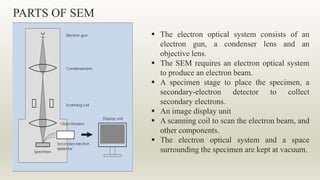
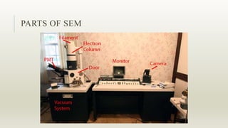
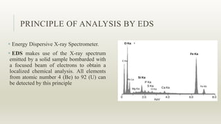
A PRESENTATION ON SCANNING ELECTRON
MICROSCOPE (SEM)
By,
Vrushank V Salimath
SEM
A scanning electron microscope (SEM) is a type of electron
microscope that produces images of a sample by scanning the
surface with a focused beam of electrons
The electrons interact with atoms in the sample, producing
various signals that contain information about the
surface topography and composition of the sample.
HISTORY OF SEM
 Max Knoll and Ernst Ruska
at the Berlin in 1931
WHY SEM ?
 Electrons have much a shorter wavelength than visible light, and
this allows electron microscopes to produce higher-resolution
images than standard light microscopes.
 Better Depth of focus, As the magnification increases in the
optical microscope the depth of focus decreases.
CHARACTERISTICS VIEWED ON SEM
 Topography- The surface feature of the object “how it looks,” its
texture
Morphology- The size and shape of the particles
Composition- The elements and the compounds the object is
composed of and the relative amounts of them
 Crystallographic information- How the atoms are arranged inside
the object.
PARTS OF SEM
 The electron optical system consists of an
electron gun, a condenser lens and an
objective lens.
 The SEM requires an electron optical system
to produce an electron beam.
 A specimen stage to place the specimen, a
secondary-electron detector to collect
secondary electrons.
 An image display unit
 A scanning coil to scan the electron beam, and
other components.
 The electron optical system and a space
surrounding the specimen are kept at vacuum.
ELECTRON GUN
 The electron gun produces an electron
beam.
 Thermo-electrons are emitted from a
filament (cathode) made of a thin
tungsten wire (about 0.1 mm) by
heating the filament at high temperature
(about 2800K).
 These thermo-electrons are gathered as
an electron beam, flowing into the
metal plate (anode) by applying a
positive voltage (1 to 30 kV) to the
anode.
CONDENSER LENS AND OBJECTIVE LENS
 Placing a lens below the electron
gun enables you to adjust the
diameter of the electron beam
 Two-stage lenses, which combine
the condenser and objective lenses ,
are located below the electron gun.
 The electron beam from the
electron gun is focused by the two-
stage lenses, and a small electron
probe is produced.
SPECIMEN STAGE
The specimen stage for a SEM
can perform the following
movements
 Horizontal movement (X, Y)
 Vertical movement (Z)
 Specimen tilting (T)
 Rotation (R)
SECONDARY ELECTRON DETECTOR
 Secondary electron detector is used for
detecting the secondary electrons emitted from
the specimen
 A scintillator (fluorescent substance) is coated
on the tip of the detector and a high voltage of
about 10 kV is applied to it.
 Electrons from the specimen are attracted to
this high voltage and then generate light when
they hit the scintillator.
 This light is directed to a photo-multiplier
tube (PMT) through a light guide.
MAGNIFICATION OF SEM
When the specimen surface is two-dimensionally
scanned by the electron beam, a SEM image appears on
the monitor screen of the display unit.
 If scan width of the electron beam is changed, the
magnification of the displayed SEM image is also
changed.
 Since the size of the monitor screen is unchanged,
decreasing the scan width increases the magnification,
whereas increasing the scan width decreases the
magnification.
 For Ex. when the size of the monitor screen is 10 cm and
the scan width of the electron beam is 1 mm, the
magnification is 100 times.
PARTS OF SEM
WHY IMAGES ARE VISIBLE?
 The SEM image appears as if you observe an object with the naked eye
 Interactions of Electrons with Specimens
When electrons enter the specimen, the electrons are scattered within the
specimen and gradually lose their energy, then they are absorbed in the
specimen.
INTERACTIONS OF ELECTRONS WITH
SPECIMENS
 Schematic diagram illustrates various signals
emitted from the specimen when the incident
electron beam enters the specimen.
 The SEM utilizes these signals to observe and
analyze the specimen surface.
 The SEM is not a simple morphology-
observation, but a versatile instrument capable of
performing other analysis.
SECONDARY ELECTRONS
 The incident electron beam enters the
specimen, secondary electrons are produced
from the emission of the valence electrons of
the constituent atoms in the specimen.
 The electrons generated at the top surface of
the specimen are emitted outside of the
specimen.
The secondary electron is used to observe the
topography, morphology of the specimen
surface.
SECONDARY ELECTRON IMAGE OF TUNGSTEN OXIDE
CRYSTAL.
BACKSCATTERED ELECTRONS
 Backscattered electrons are those scattered
backward and emitted out of the specimen.
 Backscattered electrons possess higher energy
than secondary electrons.
 The backscattered electrons are sensitive to
the composition of the specimen. The atomic
number of the constituent atoms in the
specimen is larger, the backscattered electron
yield is larger.
 Area that consists of a heavy atom appears
bright in the backscattered electron image.
Thus, this image is suitable for observing a
compositional difference.
RESOLUTION
 The SEM resolution is determined by the
diameter of the electron beam.
 The “resolution”. The resolution is defined as
“the minimum distance that can be separated as
two distinguishable points in the (SEM) image.”
 The resolution is determined by various factors:
the status of the instrument, structures of the
specimen, observation magnification, etc.
Gold particles evaporated on a carbon
plate.
GENERATION OF X-RAYS
 X-rays are called “characteristic X-rays”
because their energies (wavelengths) are
characteristic of individual elements.
Accelerated electron kicks out an electron
from the electron shell.
An electron from higher shell takes place and
releases energy in the form of x-rays.
The energy released in the X-ray is dependent
on the difference in the energies between the
shells.
K shell
Characteristic X-rays
M shell
L shell
Incident electrons
PRINCIPLE OF ANALYSIS BY EDS
 Energy Dispersive X-ray Spectrometer.
 EDS makes use of the X-ray spectrum
emitted by a solid sample bombarded with
a focused beam of electrons to obtain a
localized chemical analysis. All elements
from atomic number 4 (Be) to 92 (U) can
be detected by this principle
SEM SAMPLE PREPARATION
 Appropriate size samples
Fit in the specimen chamber
Mounted rigidly on a specimen holder
 For imaging in the SEM, specimens must be
Electrically conductive
Cleaning the surface of the specimen very important because, Surface contains many
unwanted deposits, such as dust, mud, soil etc
 Stabilizing the specimen
Stabilization is typically done with fixatives.
SEM SAMPLE PREPARATION
 Dehydrating the specimen
Water must be removed
Air-drying causes collapse and shrinkage, this is commonly achieve by
replacement of water in the cells with organic solvents such as ethanol or
acetone.
Dehydration is performed with a graded series of ethanol or acetone.
 Drying the specimen
Specimen should be completely dry
SEM SAMPLE PREPARATION
 Mounting the specimen-
Specimen has to be mounted on the holder
Mounted rigidly on a specimen holder called a specimen stub
Dry specimen is mounted on a specimen stub using an adhesive such as
epoxy resin or electrically conductive double-sided adhesive tape.
 Coating the specimen
To increase the conductivity of the specimen and to prevent the high voltage
charge on the specimen
Coated with thin layer i.e., 20nm-30nm of conductive metal.
THANK YOU

Scanning Electron Microscope

  • 1.
    A PRESENTATION ONSCANNING ELECTRON MICROSCOPE (SEM) By, Vrushank V Salimath
  • 2.
    SEM A scanning electronmicroscope (SEM) is a type of electron microscope that produces images of a sample by scanning the surface with a focused beam of electrons The electrons interact with atoms in the sample, producing various signals that contain information about the surface topography and composition of the sample.
  • 3.
    HISTORY OF SEM Max Knoll and Ernst Ruska at the Berlin in 1931
  • 4.
    WHY SEM ? Electrons have much a shorter wavelength than visible light, and this allows electron microscopes to produce higher-resolution images than standard light microscopes.  Better Depth of focus, As the magnification increases in the optical microscope the depth of focus decreases.
  • 5.
    CHARACTERISTICS VIEWED ONSEM  Topography- The surface feature of the object “how it looks,” its texture Morphology- The size and shape of the particles Composition- The elements and the compounds the object is composed of and the relative amounts of them  Crystallographic information- How the atoms are arranged inside the object.
  • 6.
    PARTS OF SEM The electron optical system consists of an electron gun, a condenser lens and an objective lens.  The SEM requires an electron optical system to produce an electron beam.  A specimen stage to place the specimen, a secondary-electron detector to collect secondary electrons.  An image display unit  A scanning coil to scan the electron beam, and other components.  The electron optical system and a space surrounding the specimen are kept at vacuum.
  • 7.
    ELECTRON GUN  Theelectron gun produces an electron beam.  Thermo-electrons are emitted from a filament (cathode) made of a thin tungsten wire (about 0.1 mm) by heating the filament at high temperature (about 2800K).  These thermo-electrons are gathered as an electron beam, flowing into the metal plate (anode) by applying a positive voltage (1 to 30 kV) to the anode.
  • 8.
    CONDENSER LENS ANDOBJECTIVE LENS  Placing a lens below the electron gun enables you to adjust the diameter of the electron beam  Two-stage lenses, which combine the condenser and objective lenses , are located below the electron gun.  The electron beam from the electron gun is focused by the two- stage lenses, and a small electron probe is produced.
  • 9.
    SPECIMEN STAGE The specimenstage for a SEM can perform the following movements  Horizontal movement (X, Y)  Vertical movement (Z)  Specimen tilting (T)  Rotation (R)
  • 10.
    SECONDARY ELECTRON DETECTOR Secondary electron detector is used for detecting the secondary electrons emitted from the specimen  A scintillator (fluorescent substance) is coated on the tip of the detector and a high voltage of about 10 kV is applied to it.  Electrons from the specimen are attracted to this high voltage and then generate light when they hit the scintillator.  This light is directed to a photo-multiplier tube (PMT) through a light guide.
  • 11.
    MAGNIFICATION OF SEM Whenthe specimen surface is two-dimensionally scanned by the electron beam, a SEM image appears on the monitor screen of the display unit.  If scan width of the electron beam is changed, the magnification of the displayed SEM image is also changed.  Since the size of the monitor screen is unchanged, decreasing the scan width increases the magnification, whereas increasing the scan width decreases the magnification.  For Ex. when the size of the monitor screen is 10 cm and the scan width of the electron beam is 1 mm, the magnification is 100 times.
  • 12.
  • 13.
    WHY IMAGES AREVISIBLE?  The SEM image appears as if you observe an object with the naked eye  Interactions of Electrons with Specimens When electrons enter the specimen, the electrons are scattered within the specimen and gradually lose their energy, then they are absorbed in the specimen.
  • 14.
    INTERACTIONS OF ELECTRONSWITH SPECIMENS  Schematic diagram illustrates various signals emitted from the specimen when the incident electron beam enters the specimen.  The SEM utilizes these signals to observe and analyze the specimen surface.  The SEM is not a simple morphology- observation, but a versatile instrument capable of performing other analysis.
  • 15.
    SECONDARY ELECTRONS  Theincident electron beam enters the specimen, secondary electrons are produced from the emission of the valence electrons of the constituent atoms in the specimen.  The electrons generated at the top surface of the specimen are emitted outside of the specimen. The secondary electron is used to observe the topography, morphology of the specimen surface.
  • 16.
    SECONDARY ELECTRON IMAGEOF TUNGSTEN OXIDE CRYSTAL.
  • 17.
    BACKSCATTERED ELECTRONS  Backscatteredelectrons are those scattered backward and emitted out of the specimen.  Backscattered electrons possess higher energy than secondary electrons.  The backscattered electrons are sensitive to the composition of the specimen. The atomic number of the constituent atoms in the specimen is larger, the backscattered electron yield is larger.  Area that consists of a heavy atom appears bright in the backscattered electron image. Thus, this image is suitable for observing a compositional difference.
  • 18.
    RESOLUTION  The SEMresolution is determined by the diameter of the electron beam.  The “resolution”. The resolution is defined as “the minimum distance that can be separated as two distinguishable points in the (SEM) image.”  The resolution is determined by various factors: the status of the instrument, structures of the specimen, observation magnification, etc. Gold particles evaporated on a carbon plate.
  • 19.
    GENERATION OF X-RAYS X-rays are called “characteristic X-rays” because their energies (wavelengths) are characteristic of individual elements. Accelerated electron kicks out an electron from the electron shell. An electron from higher shell takes place and releases energy in the form of x-rays. The energy released in the X-ray is dependent on the difference in the energies between the shells. K shell Characteristic X-rays M shell L shell Incident electrons
  • 20.
    PRINCIPLE OF ANALYSISBY EDS  Energy Dispersive X-ray Spectrometer.  EDS makes use of the X-ray spectrum emitted by a solid sample bombarded with a focused beam of electrons to obtain a localized chemical analysis. All elements from atomic number 4 (Be) to 92 (U) can be detected by this principle
  • 21.
    SEM SAMPLE PREPARATION Appropriate size samples Fit in the specimen chamber Mounted rigidly on a specimen holder  For imaging in the SEM, specimens must be Electrically conductive Cleaning the surface of the specimen very important because, Surface contains many unwanted deposits, such as dust, mud, soil etc  Stabilizing the specimen Stabilization is typically done with fixatives.
  • 22.
    SEM SAMPLE PREPARATION Dehydrating the specimen Water must be removed Air-drying causes collapse and shrinkage, this is commonly achieve by replacement of water in the cells with organic solvents such as ethanol or acetone. Dehydration is performed with a graded series of ethanol or acetone.  Drying the specimen Specimen should be completely dry
  • 23.
    SEM SAMPLE PREPARATION Mounting the specimen- Specimen has to be mounted on the holder Mounted rigidly on a specimen holder called a specimen stub Dry specimen is mounted on a specimen stub using an adhesive such as epoxy resin or electrically conductive double-sided adhesive tape.  Coating the specimen To increase the conductivity of the specimen and to prevent the high voltage charge on the specimen Coated with thin layer i.e., 20nm-30nm of conductive metal.
  • 24.