Downloaded 270 times

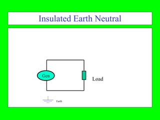

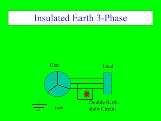

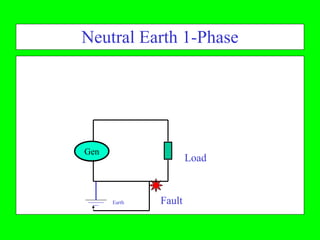
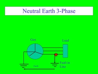

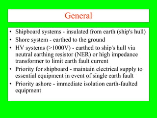

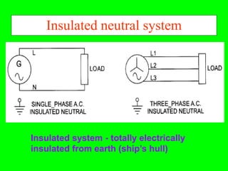
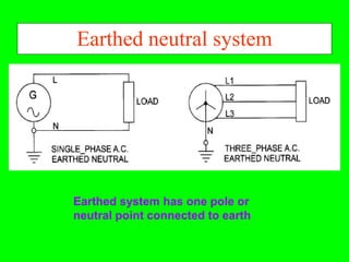


This document discusses electrical safety and protection on ships. It notes that most merchant ships have a 440V 3-phase 3-wire power system. Larger loads require higher voltage systems. Switchboards distribute power and include open and dead front types. Safety requirements to prevent electric shock are described, including types of neutral connections and operational considerations when connecting to shore power.