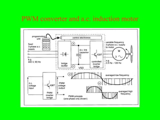
Download as PDF, PPTX

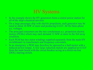

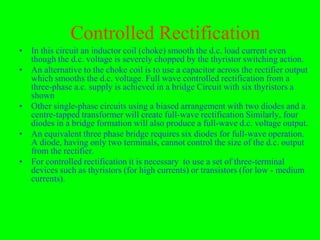
![Impulse High Voltage
• Impulse voltages (IVs) are required in hv tests to simulate the
stresses due to external and internal overvoltages, and also for
fundamental investigations of the breakdown mechanisms.
• Usually generated by discharging hv capacitors through
switching gaps onto a network of resistors and capacitors.
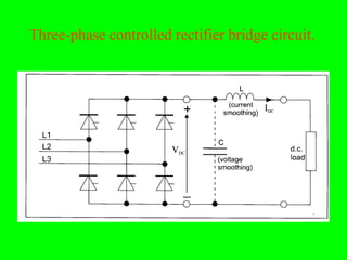
• In hv technology, a single, unipolar voltage is termed an
impulse voltage.
• Rectangular and wedge-shaped IVs are normally used for basic
experiments while for testing purposes, double exponential IVs
are used.
• Standard test of impulse voltages can be represented as double
exponential wave, and its mathematical equation is defined as
follows;
V = Vo [exp(-αt) – exp(-βt)]
Where α and β are constants of microsecond values.](https://image.slidesharecdn.com/hvgenration-transpformation-conversondistribution-revisedl-121110015940-phpapp02/85/Hv-genration-transpformation-converson-distribution-revisedl-56-320.jpg)
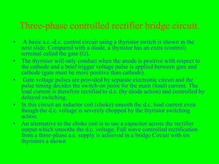
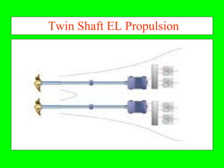
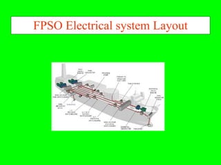
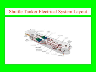
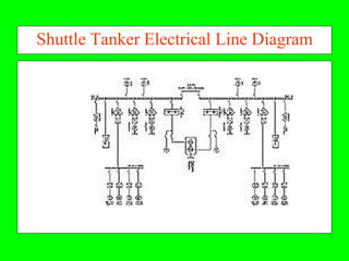
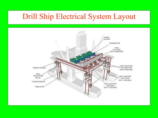

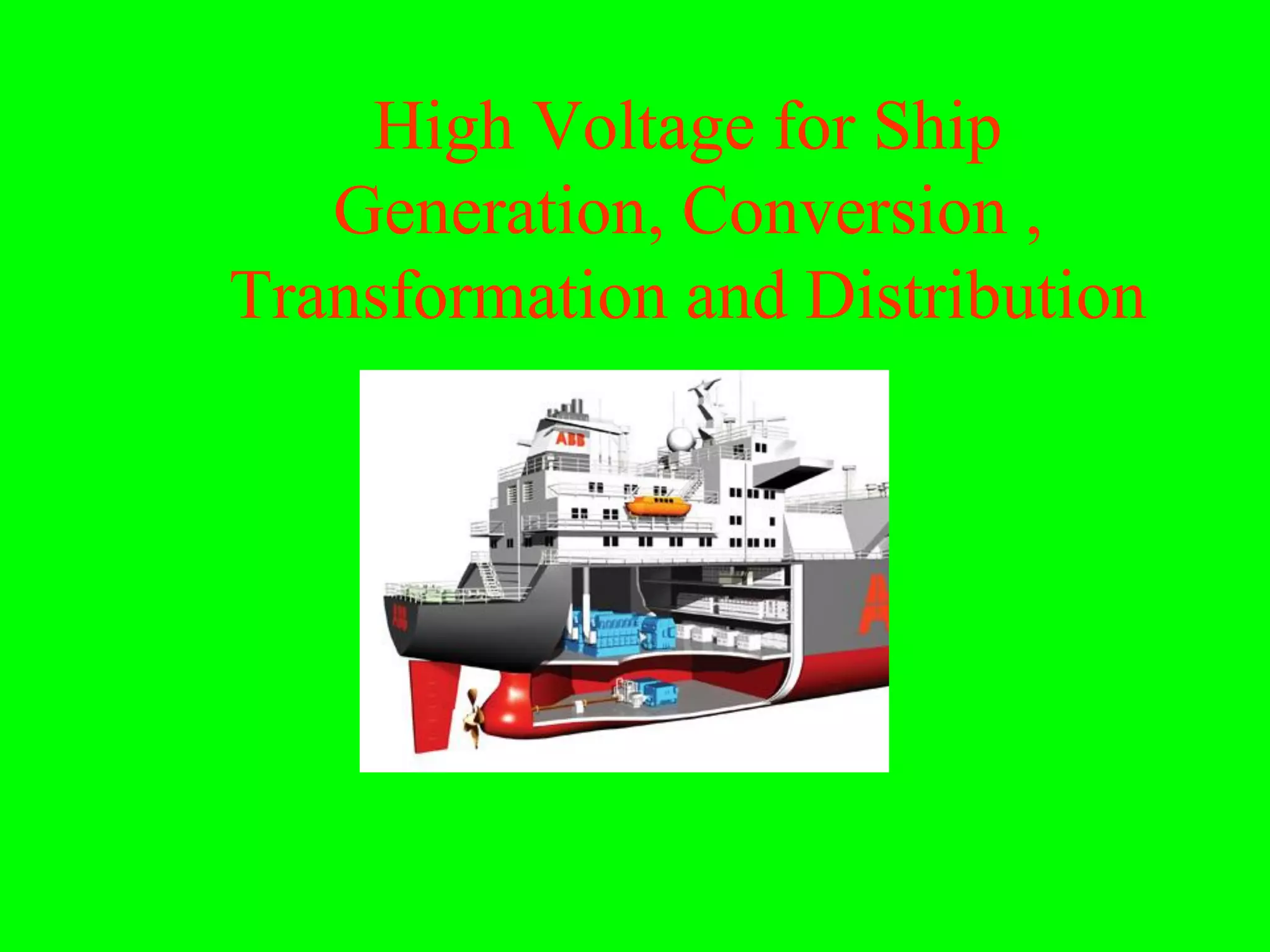
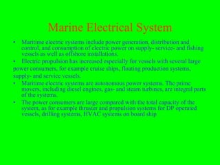
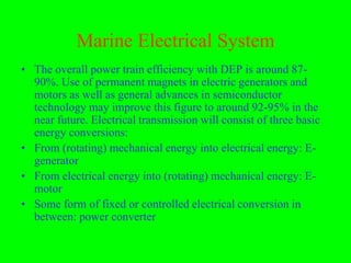
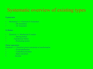
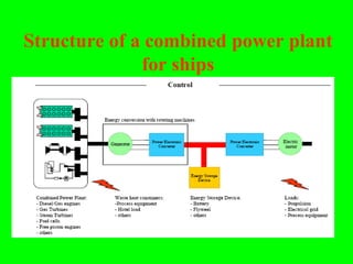
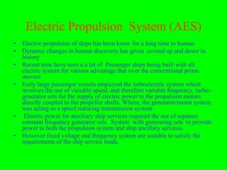
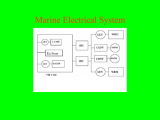
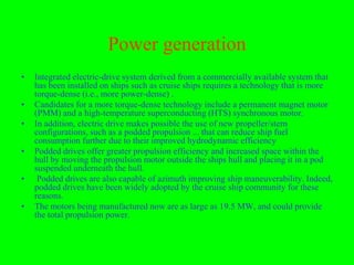
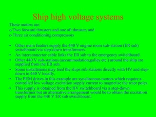
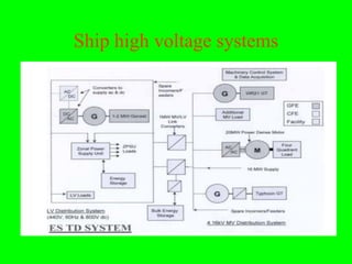
The document discusses marine electrical systems and electric propulsion systems for ships. Key points include: - Marine electrical systems include power generation, distribution, and consumption of electric power on various vessels. Electric propulsion has increased for vessels with multiple large power consumers like cruise ships. - Electrical transmission consists of mechanical energy converted to electrical energy by generators, electrical energy converted to mechanical energy by motors, and power conversion in between via converters. - Electric propulsion provides advantages over conventional systems like increased efficiency and flexibility in component placement. Integrated electric drive propulsion with advanced technologies can further improve efficiency. - High voltage distribution systems above 440V are needed to reduce cable sizes as power demands on ships increase. Components