(1) Five classical types of busbar protection systems are discussed: system protection, frame-earth protection, differential protection, phase comparison protection, and directional blocking protection. System protection and phase comparison protection are only suitable for small substations, while frame-earth and differential protection are discussed in more detail.
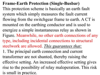
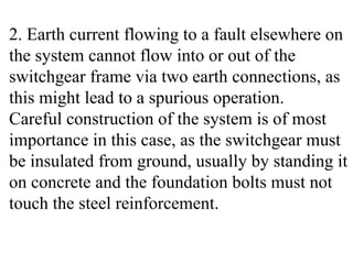
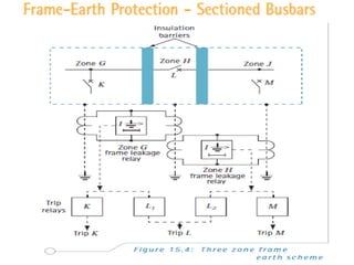
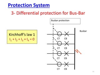
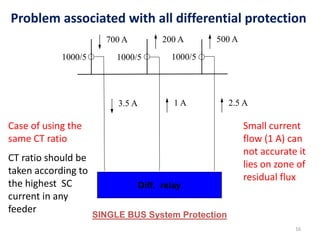
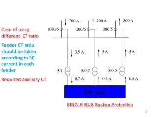
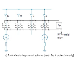
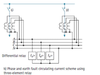
(2) Frame-earth protection measures fault current flowing from the switchgear frame to earth. Differential protection compares currents flowing into and out of the busbar and trips if they are not equal.
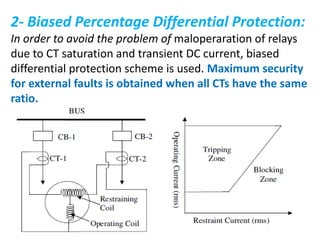
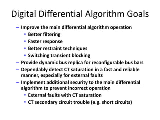
(3) Modern digital differential algorithms aim to improve filtering, response time, restraint techniques, and transient blocking compared to classical schemes.