Download as PDF, PPTX
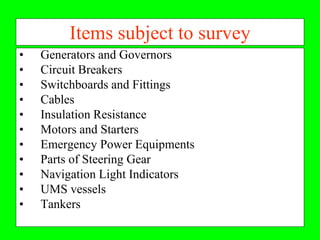
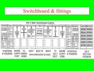


This document outlines the marine electrical standard requirements for electrical machinery and systems on ships. It discusses SOLAS regulations regarding main and emergency electrical power sources. Equipment like generators, circuit breakers, switchboards, cables, and motors are subject to periodic surveys to check they are maintained according to classification standards. The objectives are to understand general requirements for electrical power provision and ensure safety.