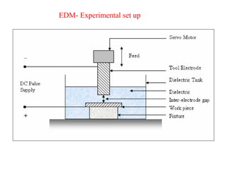
History
• In 1770,English Physicist Joseph Priestley studied the erosive effect of
electrical discharges.
• Furthering Priestley's research, the EDM process was invented by two Russian
scientists, Dr. B.R. Lazarenko and Dr. N.I. Lazarenko in 1943.
• In their efforts to exploit the destructive effects of an electrical discharge, they
developed a controlled process for machining of metals.
• Their initial process used a spark machining process, named after the succession of
sparks (electrical discharges) that took place between two electrical conductors
immersed in a dielectric fluid.
• The discharge generator effect used by this machine, known as the Lazarenko
Circuit, was used for many years in the construction of generators for electrical
discharge.
6.
History- cont.
• In1952, the manufacturer Charmilles created the first machine using the
spark machining process and was presented for the first time at the European
Machine Tool Exhibition in 1955.
• In 1969, Agie launched the world's first numerically controlled wire-cut
EDM machine.
• Seibu developed the first CNC wire EDM machine in 1972 and the first
system was manufactured in Japan.
• Recently, the machining speed has gone up by 20 times.
• This has decreased machining costs by at least 30 percent and improved the
surface finish by a factor of 1.5
7.
General Aspects ofEDM
• EDM is a machining method primarily used for hard metals or those that
would be very difficult to machine with traditional techniques.
• EDM typically works with materials that are electrically conductive,
although methods for machining insulating ceramics with EDM have been
proposed.
• EDM can cut intricate contours or cavities in hardened steel without the need
for heat treatment to soften and re-harden them.
• This method can be used with any other metal or metal alloy such as
titanium, hastelloy, kovar, and inconel.
• Applications of this process to shape polycrystalline diamond tools have
been reported.
8.
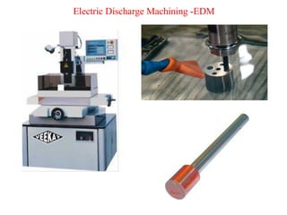
EDM – Components
•Electric power supply
• Dielectric medium
• Work piece & tool
• Servo control unit.
• The work piece and tool are electrically connected to a DC power supply.
• The current density in the discharge of the channel is of the order of 10000 A/cm2 and
power density is nearly 500 MW/cm2 .
• A gap, known as SPARK GAP in the range, from 0.005 mm to 0.05 mm is maintained
between the work piece and the tool.
• Dielectric slurry is forced through this gap at a pressure of 2 kgf/cm2 or lesser
9.
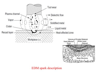
• It isa process of metal removal based on the principle of material removal by
an interrupted electric spark discharge between the electrode tool and the
work piece.
EDM – Working Principle
• In EDM, a potential difference is applied between the tool and workpiece.
• Essential - Both tool and work material are to be conductors.
• The tool and work material are immersed in a dielectric medium.
• Generally kerosene or deionised water is used as the dielectric medium.
• A gap is maintained between the tool and the workpiece.
• Depending upon the applied potential difference (50 to 450 V) and the gap
between the tool and workpiece, an electric field would be established.
• Generally the tool is connected to the negative terminal (cathode) of the
generator and the workpiece is connected to positive terminal (anode).
10.
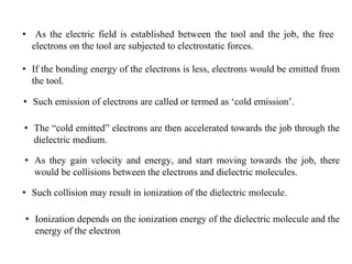
• As theelectric field is established between the tool and the job, the free
electrons on the tool are subjected to electrostatic forces.
• If the bonding energy of the electrons is less, electrons would be emitted from
the tool.
• Such emission of electrons are called or termed as ‘cold emission’.
• The “cold emitted” electrons are then accelerated towards the job through the
dielectric medium.
• As they gain velocity and energy, and start moving towards the job, there
would be collisions between the electrons and dielectric molecules.
• Such collision may result in ionization of the dielectric molecule.
• Ionization depends on the ionization energy of the dielectric molecule and the
energy of the electron
11.
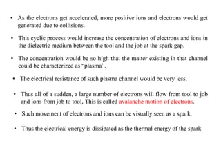
• As theelectrons get accelerated, more positive ions and electrons would get
generated due to collisions.
• This cyclic process would increase the concentration of electrons and ions in
the dielectric medium between the tool and the job at the spark gap.
• The concentration would be so high that the matter existing in that channel
could be characterized as “plasma”.
• The electrical resistance of such plasma channel would be very less.
• Thus all of a sudden, a large number of electrons will flow from tool to job
and ions from job to tool, This is called avalanche motion of electrons.
• Such movement of electrons and ions can be visually seen as a spark.
• Thus the electrical energy is dissipated as the thermal energy of the spark
12.
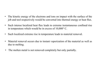
• The kineticenergy of the electrons and ions on impact with the surface of the
job and tool respectively would be converted into thermal energy or heat flux.
• Such intense localized heat flux leads to extreme instantaneous confined rise
in temperature which would be in excess of 10,000° C.
• Such localized extreme rise in temperature leads to material removal.
• Material removal occurs due to instant vaporization of the material as well as
due to melting.
• The molten metal is not removed completely but only partially.
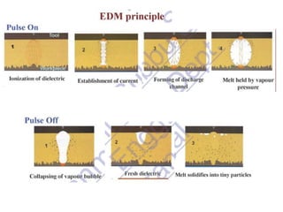
13.
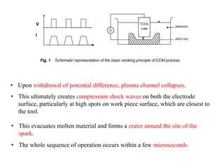
• Upon withdrawalof potential difference, plasma channel collapses.
• This ultimately creates compression shock waves on both the electrode
surface, particularly at high spots on work piece surface, which are closest to
the tool.
• This evacuates molten material and forms a crater around the site of the
spark.
• The whole sequence of operation occurs within a few microseconds
14.
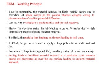
• Thus tosummarize, the material removal in EDM mainly occurs due to
formation of shock waves as the plasma channel collapse owing to
discontinuation of applied potential difference.
EDM – Working Principle
• Generally the workpiece is made positive and the tool negative.
• Hence, the electrons strike the job leading to crater formation due to high
temperature and melting and material removal.
• Similarly, the positive ions impinge on the tool leading to tool wear.
• In EDM, the generator is used to apply voltage pulses between the tool and
job.
• A constant voltage is not applied. Only sparking is desired rather than arcing.
• Arcing leads to localized material removal at a particular point whereas
sparks get distributed all over the tool surface leading to uniform material
removal.
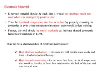
Electrode Material
• Electrodematerial should be such that it would not undergo much tool
wear when it is impinged by positive ions.
✔ High electrical conductivity – electrons are cold emitted more easily and
there is less bulk electrical heating
• Thus the localized temperature rise has to be less by properly choosing its
properties or even when temperature increases, there would be less melting.
• Further, the tool should be easily workable as intricate shaped geometric
features are machined in EDM.
Thus the basic characteristics of electrode materials are:
✔ High thermal conductivity – for the same heat load, the local temperature
rise would be less due to faster heat conducted to the bulk of the tool and
thus less tool wear.
18.
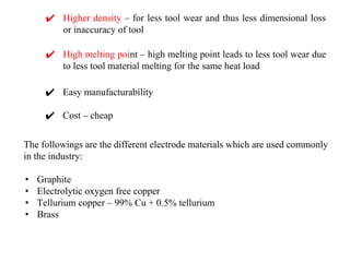
✔ Higher density– for less tool wear and thus less dimensional loss
or inaccuracy of tool
The followings are the different electrode materials which are used commonly
in the industry:
• Graphite
• Electrolytic oxygen free copper
• Tellurium copper – 99% Cu + 0.5% tellurium
• Brass
✔ High melting point – high melting point leads to less tool wear due
to less tool material melting for the same heat load
✔ Easy manufacturability
✔ Cost – cheap
19.
EDM – Dielectric
•In EDM, material removal mainly occurs due to thermal evaporation and
melting.
• Thermal processing is carried out in the absence of oxygen so that the process
can be controlled and oxidation avoided.
• Oxidation often leads to poor surface conductivity (electrical) of the workpiece
hindering further machining.
• Hence, dielectric fluid should provide an oxygen free machining environment.
• Further it should have enough strong dielectric resistance so that it does not
breakdown electrically too easily.
• But at the same time, it should ionize when electrons collide with its molecule.
• Generally kerosene and deionized water are used as dielectric fluid in EDM.
20.
EDM – Dielectric
•Tap water cannot be used as it ionizes too early and thus breakdown due to
presence of salts.
• Dielectric medium is generally flushed around the spark zone.
• It is also applied through the tool to achieve efficient removal of molten
material.
• Three important functions of a dielectric medium in EDM:
1. Insulates the gap between the tool and work, thus preventing a
spark to form until the gap voltage are correct.
2. Cools the electrode, workpiece and solidifies the molten metal
particles.
3. Flushes the metal particles out of the working gap to maintain
ideal cutting conditions, increase metal removal rate.
• It must be filtered and circulated at constant pressure.
21.
EDM – Dielectric
•The main requirements of the EDM dielectric fluids are adequate viscosity, high
flash point, good oxidation stability, minimum odor, low cost, and good
electrical discharge efficiency.
• For most EDM operations kerosene is used with certain additives that prevent
gas bubbles and de-odoring.
• Silicon fluids and a mixture of these fluids with petroleum oils have given
excellent results.
• Other dielectric fluids with a varying degree of success include aqueous
solutions of ethylene glycol, water in emulsions, and distilled water.
22.
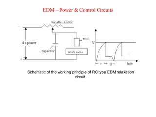
EDM – Power& Control Circuits
Schematic of the working principle of RC type EDM relaxation
circuit.
23.
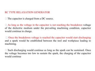
RC TYPE RELAXATIONGENERATOR
The capacitor is charged from a DC source.
As long as the voltage in the capacitor is not reaching the breakdown voltage
of the dielectric medium under the prevailing machining condition, capacitor
would continue to charge.
Once the breakdown voltage is reached the capacitor would start discharging
and a spark would be established between the tool and workpiece leading to
machining.
Such discharging would continue as long as the spark can be sustained. Once
the voltage becomes too low to sustain the spark, the charging of the capacitor
would continue
24.
▪ A seriesof voltage pulses of magnitude about 20 to 120 V and frequency on the order
of 5 to 10 kHz is applied between the two electrodes.
▪ Is employed in old EDM machines
▪ Low discharge time prevents full erosion time
▪ MRR is not high in case of RC relaxation circuit
25.
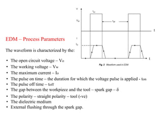
EDM – ProcessParameters
The waveform is characterized by the:
• The working voltage – Vw
• The maximum current – Io
• The pulse on time – the duration for which the voltage pulse is applied - ton
• The pulse off time – toff
• The gap between the workpiece and the tool – spark gap – δ
• The polarity – straight polarity – tool (-ve)
• The dielectric medium
• External flushing through the spark gap.
• The open circuit voltage – Vo
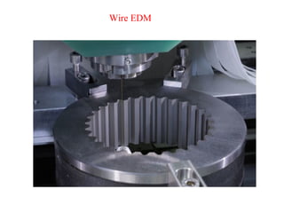
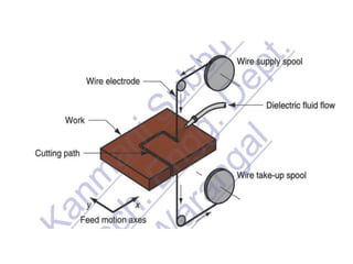
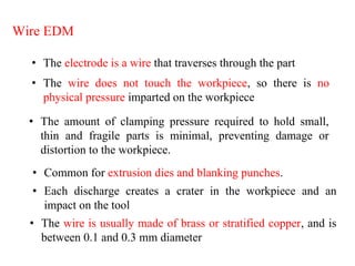
Wire EDM
• Theelectrode is a wire that traverses through the part
• The wire does not touch the workpiece, so there is no
physical pressure imparted on the workpiece
• The amount of clamping pressure required to hold small,
thin and fragile parts is minimal, preventing damage or
distortion to the workpiece.
• Common for extrusion dies and blanking punches.
• Each discharge creates a crater in the workpiece and an
impact on the tool
• The wire is usually made of brass or stratified copper, and is
between 0.1 and 0.3 mm diameter
29.
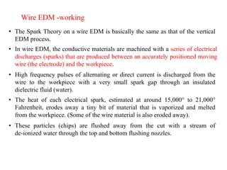
• The SparkTheory on a wire EDM is basically the same as that of the vertical
EDM process.
Wire EDM -working
• In wire EDM, the conductive materials are machined with a series of electrical
discharges (sparks) that are produced between an accurately positioned moving
wire (the electrode) and the workpiece.
• High frequency pulses of alternating or direct current is discharged from the
wire to the workpiece with a very small spark gap through an insulated
dielectric fluid (water).
• The heat of each electrical spark, estimated at around 15,000° to 21,000°
Fahrenheit, erodes away a tiny bit of material that is vaporized and melted
from the workpiece. (Some of the wire material is also eroded away).
• These particles (chips) are flushed away from the cut with a stream of
de-ionized water through the top and bottom flushing nozzles.
30.
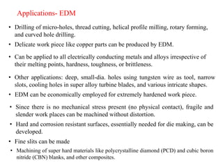
• Drilling ofmicro-holes, thread cutting, helical profile milling, rotary forming,
and curved hole drilling.
Applications- EDM
• Delicate work piece like copper parts can be produced by EDM.
• Can be applied to all electrically conducting metals and alloys irrespective of
their melting points, hardness, toughness, or brittleness.
• Other applications: deep, small-dia. holes using tungsten wire as tool, narrow
slots, cooling holes in super alloy turbine blades, and various intricate shapes.
• EDM can be economically employed for extremely hardened work piece.
• Since there is no mechanical stress present (no physical contact), fragile and
slender work places can be machined without distortion.
• Hard and corrosion resistant surfaces, essentially needed for die making, can be
developed.
• Fine slits can be made
• Machining of super hard materials like polycrystalline diamond (PCD) and cubic boron
nitride (CBN) blanks, and other composites.
31.
Disadvantages
• Slow rateof material removal.
• For economic production, the surface finish specified should not be too fine.
• Reproducing sharp corners on the workpiece is difficult due to electrode wear.
• Specific power consumption is very high.
• "Overcut" is formed.
• Excessive tool wear occurs during machining.
• Electrically non-conductive materials can be machined only with specific set-
up
• Profile machining of complicated contours is not possible at required tolerances
• Machining heats the work piece and hence causes changes in surface and
metallurgical properties
32.
Advantages of EDM
•Complex shapes that would otherwise be difficult to produce with
conventional cutting tools. Complex die sections and molds can be
produced accurately, faster, and at lower costs.
• Extremely hard material to very close tolerances.
• Very small work pieces where conventional cutting tools may damage the
part from excess cutting tool pressure.
• Since the tool does not touch the workpiece, no cutting force is generated;
therefore, very fragile parts can be machined without any distortion.
• Hardened work pieces can be machined eliminating the deformation caused
by heat treatment.
33.
• The EDMprocess is burr-free.
• Conventional EDM machines can be programmed for vertical machining,
orbital, vectorial, directional, helical, conical, rotational, spin and indexing
machining cycles.
34.
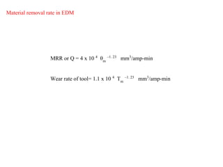
MRR or Q= 4 x 10 4
θm
–1. 23
mm3
/amp-min
Material removal rate in EDM
Wear rate of tool= 1.1 x 10 4
Tm
–1. 23
mm3
/amp-min
35.
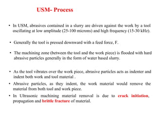
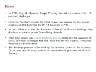
MRR for RCcircuited EDM
V = V0
(1-e –t/RC
)
V= 0.7 V0
-0.9 V0
Frequency of spark, f = 1/tc
= ________1___________
RC loge
[ V0
/ (V0
-Vd)]
The energy released per spark is given by E = 0.5 (C Vd
2
)
Power consumed , W= 0.5 (C Vd
2
) x frequency of sparking
Q = 27.4 W 1. 54
, where Q is the removal rate in mm3
/min and W is the power
input kw.
Q = K 0.5 (C Vd
2
) f
For steel
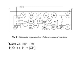
• Electrochemical machininguses an electrolyte and electrical
current to ionize and remove metal atoms
• Can machine complex cavities in high-strength materials
• Leaves a burr-free surface
• Not affected by the strength, hardness or toughness of the
material
Features of ECM
41.
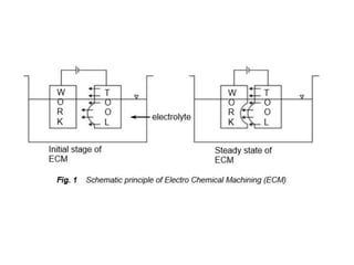
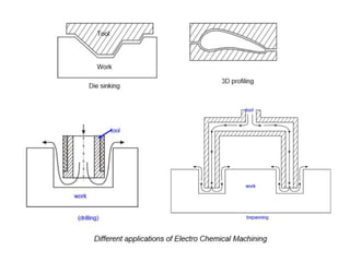
Operating Principle
• Asthe tool approaches the work piece it erodes the negative
shape of it.
• Thus complex shapes are made from soft tool material and used
to produce negative duplicates of it.
• This process is called electrochemical sinking
• In ECM, a dc voltage (10-25 V) is applied across the gap
between a pre-shaped cathode tool and an anode workpiece.
• The workpiece is dissolved by an electrochemical reaction to
the shape of the tool.
• The electrolyte flows at high speed (10-60 m/s) through the gap
(0.1-0.6mm) to dissipate heat and wash away the dissolved
metal.
42.
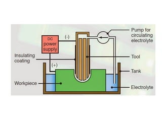
Main Subsystems
1. Thepower supply.
2. The electrolyte circulation system.
3. The control system.
4. The machine.
43.
ECM Components- Powersupply
• The current density must be high.
• The gap between the tool and the work piece must be low for
higher accuracy, thus the voltage must be low to avoid a short
circuit.
• The control system also uses a part of this electrical power.
• The power needed to operate the ECM is obviously electrical.
44.
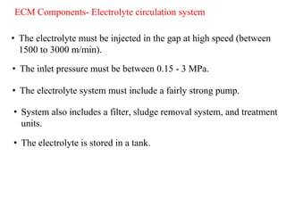
ECM Components- Electrolytecirculation system
• The electrolyte must be injected in the gap at high speed (between
1500 to 3000 m/min).
• The inlet pressure must be between 0.15 - 3 MPa.
• The electrolyte system must include a fairly strong pump.
• System also includes a filter, sludge removal system, and treatment
units.
• The electrolyte is stored in a tank.
45.
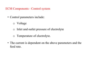
ECM Components -Control system
• Control parameters include:
o Voltage
o Inlet and outlet pressure of electrolyte
o Temperature of electrolyte.
• The current is dependent on the above parameters and the
feed rate.
46.
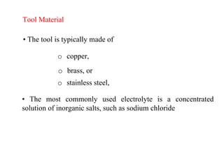
Tool Material
• Thetool is typically made of
o copper,
o brass, or
o stainless steel,
• The most commonly used electrolyte is a concentrated
solution of inorganic salts, such as sodium chloride
47.
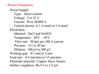
Process Parameters
Power Supply:
Type:direct current
Voltage: 2 to 35 V
Current: 50 to 40,000 A
Current density: 0.1 A/mm2 to 5 A/mm2
Electrolyte:
Material: NaCl and NaNO3
Temperature : 20°C – 50°C
Flow rate: 20 lpm per 100 A current
Pressure: 0.5 to 20 bar
Dilution: 100 g/l to 500 g/l
Working gap: 0.1 mm to 2 mm
Feed rate: 0.5 mm/min to 15 mm/min
Electrode material: Copper, brass, bronze
Surface roughness: Ra 0.2 to 1.5 μm
48.
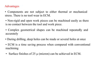
Advantages
• Components arenot subject to either thermal or mechanical
stress. There is no tool wear in ECM.
• Non-rigid and open work pieces can be machined easily as there
is no contact between the tool and work piece.
• Complex geometrical shapes can be machined repeatedly and
accurately
• ECM is a time saving process when compared with conventional
machining
• During drilling, deep holes can be made or several holes at once
• Surface finishes of 25 µ (micron) can be achieved in ECM.
49.
Disadvantages
• More expensivethan conventional machining.
• Need more area for installation.
• Electrolytes may destroy the equipment.
• Not environmentally friendly (sludge and other waste)
• High energy consumption.
• Material has to be electrically conductive.
Products
• The twomost common products of ECM are turbine/compressor
blades and rifle barrels. Each of those parts require machining of
extremely hard metals with certain mechanical specifications that
would be really difficult to perform on conventional machines.
• Some of these mechanical characteristics achieved by ECM
are:
Stress free grooves.
Any groove geometry.
Any conductive metal can be machined.
Repeatable accuracy of 0.005”.
High surface finish.
Fast cycle time
53.
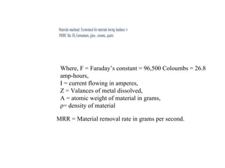
Where, F =Faraday’s constant = 96,500 Coloumbs = 26.8
amp-hours,
I = current flowing in amperes,
Z = Valances of metal dissolved,
A = atomic weight of material in grams,
ρ= density of material
MRR = Material removal rate in grams per second.
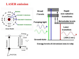
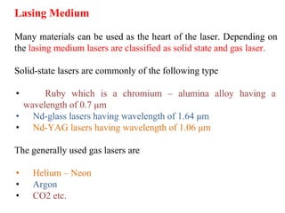
Lasing Medium
Many materialscan be used as the heart of the laser. Depending on
the lasing medium lasers are classified as solid state and gas laser.
Solid-state lasers are commonly of the following type
• Ruby which is a chromium – alumina alloy having a
wavelength of 0.7 μm
• Nd-glass lasers having wavelength of 1.64 μm
• Nd-YAG lasers having wavelength of 1.06 μm
The generally used gas lasers are
• Helium – Neon
• Argon
• CO2 etc.
60.
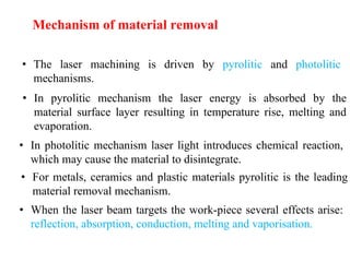
• The lasermachining is driven by pyrolitic and photolitic
mechanisms.
• In pyrolitic mechanism the laser energy is absorbed by the
material surface layer resulting in temperature rise, melting and
evaporation.
• In photolitic mechanism laser light introduces chemical reaction,
which may cause the material to disintegrate.
• For metals, ceramics and plastic materials pyrolitic is the leading
material removal mechanism.
• When the laser beam targets the work-piece several effects arise:
reflection, absorption, conduction, melting and vaporisation.
Mechanism of material removal
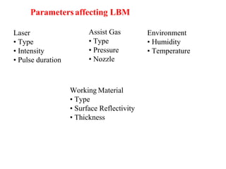
Working Material
• Type
•Surface Reflectivity
• Thickness
Parametersaffecting LBM
Assist Gas
• Type
• Pressure
• Nozzle
Environment
• Humidity
• Temperature
Laser
• Type
• Intensity
• Pulse duration
64.
Heavy Manufacturing:
• Seamand spot welding
• Cladding and drilling
Applications
Light Manufacturing:
• Engraving
• Drilling
Electronics:
• Skiving of circuits
• Wire stripping
65.
Applications
• For makingvery small holes
• Cutting of non-conductive and refractory materials
• Cutting complex profiles in thin and hard materials
• Partial cutting and engraving
• To project intense energy to a small area- to illuminate, melt,
weld, perforate or ignite
• Can be used for mass micromachining production
• Selective heat treating of materials
• To project intense energy to a small area- to illuminate, melt,
weld, perforate or ignite
66.
LBM – Advantages
Inlaser machining there is no physical tool. Thus no machining
force or wear of the tool takes place
Large aspect ratio in laser drilling can be achieved along with
acceptable accuracy or dimension.
Micro-holes can be drilled in difficult – to – machine materials
Heat affected zone specially in pulse laser processing is not very
significant due to shorter pulse duration
Laser beam can be sent to longer distances, without diffraction. It
can also be focused at one place thereby generating a lot of heat. It is
thus possible to weld, drill and cut areas not readily accessible
67.
Heat treated andmagnetic materials can be welded without losing
their properties
Laser welding is possible in any environment through transparent
materials. Distortion is negligible and any two materials can be
joined together.
Deep holes of very short diameter can be drilled by using
unidirectional multiple pulses
68.
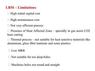
LBM – Limitations
Highinitial capital cost
High maintenance cost
Not very efficient process
Presence of Heat Affected Zone – specially in gas assist CO2
laser cutting
Thermal process – not suitable for heat sensitive materials like
aluminium, glass fibre laminate and some plastics
Low MRR
Not suitable for too deep holes
Machines holes not round and straight
69.
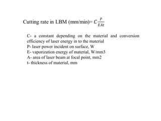
C- a constantdepending on the material and conversion
efficiency of laser energy in to the material
P- laser power incident on surface, W
E- vaporization energy of material, W/mm3
A- area of laser beam at focal point, mm2
t- thickness of material, mm
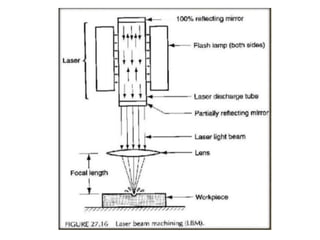
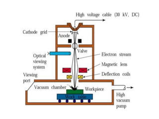
EBM – PROCESS
•Electron beam (negatively charged particles) is generated in an
electron beam gun.
• Electron beam gun provides high velocity electrons over a very
small spot size.
• Due to pattern of electrostatic field produced by grid cup,
electrons are focused and made to flow in the form of a
converging beam through anode.
• The electrons are accelerated while passing through the anode
by applying high voltage at anode.
73.
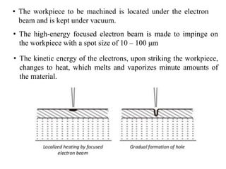
• The workpieceto be machined is located under the electron
beam and is kept under vacuum.
• The high-energy focused electron beam is made to impinge on
the workpiece with a spot size of 10 – 100 μm
• The kinetic energy of the electrons, upon striking the workpiece,
changes to heat, which melts and vaporizes minute amounts of
the material.
74.
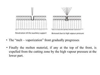
• The “melt– vaporization” front gradually progresses
• Finally the molten material, if any at the top of the front, is
expelled from the cutting zone by the high vapour pressure at the
lower part.
75.
• The wholeprocess is carried out in a vacuum chamber
• The gun in EBM is used in pulsed mode. Holes can be drilled in
thin sheets using a single pulse. For thicker plates, multiple
pulses would be required. Penetration till the auxiliary support
Removal due to high vapour pressure
76.
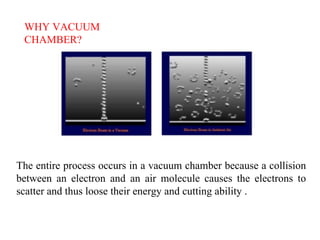
WHY VACUUM
CHAMBER?
The entireprocess occurs in a vacuum chamber because a collision
between an electron and an air molecule causes the electrons to
scatter and thus loose their energy and cutting ability .
77.
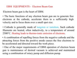
EBM EQUIPMENTS -Electron Beam Gun
Electron beam gun is the heart of EBM.
• The basic functions of any electron beam gun are to generate free
electrons at the cathode, accelerate them to a sufficiently high
velocity and to focus them over a small spot size.
• Cathode is generally made of tungsten or tantalum. Such cathode
filaments are heated, often inductively, to a temperature of around
2500°C. Heating leads to thermo-ionic emission of electrons.
• A combination of repelling forces from the negative cathode and the
attracting forces from the positive anode causes the free electrons to
be accelerated and directed toward the work piece.
• One of the major requirements of EBM operation of electron beam
gun is maintenance of desired vacuum is achieved and maintained
using a combination of rotary pump and diffusion pump.
78.
EBM PROCESS –PARAMETERS
Process parameters which directly affect the machining
characteristics in EBM are:
• The accelerating voltage – electrons get accelerated at high
voltage.
• The beam current – related to the number of electrons emitted by
the cathode or available in the beam. Beam current can be as low
as 200 μamp to 1 amp.
• Pulse duration – pulse duration can be as low as 50 μs to as long
as 15 ms.
• Energy per pulse
79.
• Power perpulse
• Lens current
• Spot size
• Power density
– Spot size is controlled by degree of focusing achieved
by the electromagnetic lenses. For a lower spot size, the
material removal would be faster though the size of the
hole would be smaller.
– The energy density and power density is governed by
energy per pulse duration and spot size .
80.
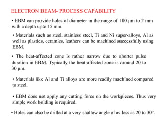
ELECTRON BEAM- PROCESSCAPABILITY
• EBM can provide holes of diameter in the range of 100 μm to 2 mm
with a depth upto 15 mm.
• Materials such as steel, stainless steel, Ti and Ni super-alloys, Al as
well as plastics, ceramics, leathers can be machined successfully using
EBM.
• The heat-affected zone is rather narrow due to shorter pulse
duration in EBM. Typically the heat-affected zone is around 20 to
30 μm.
• Materials like Al and Ti alloys are more readily machined compared
to steel.
• EBM does not apply any cutting force on the workpieces. Thus very
simple work holding is required.
• Holes can also be drilled at a very shallow angle of as less as 20 to 30°.
81.
DESIGN CONSIDERATIONS
• Non-reflectiveworkpiece surfaces are preferable
• Sharp corners are difficult to produce; deep cuts produce tapers
• Consider the effects of high temperature on the workpiece
material
• Parts should match the size of the vacuum chamber
82.
EBM - ADVANTAGES
•Extremely close tolerances can be maintained
• Heat affected zone are minimum
• It can machine almost any material irrespective of their
mechanical properties
• The beam can be concentrated on a very small area
• It produces better surface finish and narrow kerf
• Thermal distortion is least
• The process is fast because it is entirely non-mechanical.
83.
EBM - LIMITATIONS
•The equipment cost is very high.
• The interaction of the electron beam with work piece surface
produces hazardous X-ray. Hence shielding is necessary
• Vacuum is essentially required.
• Because of very low material removal rate, the process is
economical only for small volume cuts.
• Skilled labour is required to accelerate the electrons.
• Very high voltage is required to accelerate the electrons.
• The process can machine only thinner parts.
84.
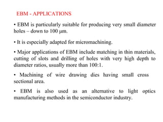
EBM - APPLICATIONS
•EBM is particularly suitable for producing very small diameter
holes – down to 100 μm.
• It is especially adapted for micromachining.
• Major applications of EBM include matching in thin materials,
cutting of slots and drilling of holes with very high depth to
diameter ratios, usually more than 100:1.
• Machining of wire drawing dies having small cross
sectional area.
• EBM is also used as an alternative to light optics
manufacturing methods in the semiconductor industry.
85.
• Because electronshave a shorter wavelength than light and can
be easily focused, electron-beam methods are particularly
useful for high-resolution lithography and for the manufacture
of complex integrated circuits
• Welding can also be done with an electron beam, notably in the
manufacture of aircraft engine parts
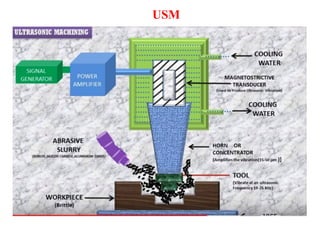
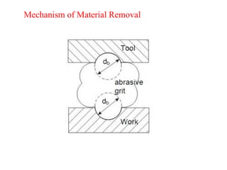
• In USM,abrasives contained in a slurry are driven against the work by a tool
oscillating at low amplitude (25-100 microns) and high frequency (15-30 kHz).
USM- Process
• The machining zone (between the tool and the work piece) is flooded with hard
abrasive particles generally in the form of water based slurry.
• In Ultrasonic machining material removal is due to crack initiation,
propagation and brittle fracture of material.
• As the tool vibrates over the work piece, abrasive particles acts as indenter and
indent both work and tool material .
• Abrasive particles, as they indent, the work material would remove the
material from both tool and work piece.
• Generally the tool is pressed downward with a feed force, F.
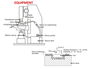
92.
Ultrasonic Machine consistsof :
1. High power sine wave generator.
2. Piezo electric or Magneto-strictive Transducer.
3. Tool Holder.
4. Tool.
93.
High Power SineWave Generator
• This unit converts low frequency (50 Hz) electrical power to
high frequency (20kHz) electrical power.
Transducer
• The high frequency electrical signal is transmitted to transducer
which converts it into high frequency low amplitude vibration.
• Essentially transducer converts electrical energy to mechanical
vibration. There are two types of transducer used
• 1. Piezo electric transducer
• 2. Magneto-strictive transducer.
94.
Magnetostrictive Transducer
• Thesetransducer are made of nickel , nickel alloy sheets.
• Their conversion efficiency is about 20-30%.
• Such transducers are available up to 2000 Watts.
• The maximum change in length can be achieved is about 25
microns.
95.
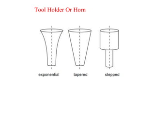
Tool Holder OrHorn
• The tool holder holds and connects the tool to the transducer. It
virtually transmits the energy and in some cases, amplifies the
amplitude of vibration.
• Material of tool should have good acoustic properties, high
resistance to fatigue cracking.
• Due measures should be taken to avoid ultrasonic welding
between transducer and tool holder.
• Commonly used tool holders are Monel, titanium, stainless
steel.
• Tool holders are more expensive, demand higher operating
cost.
TOOL
• Tools aremade of relatively tough and ductile materials like
Brass, Stainless steel or Mild steel so that Tool wear rate
(TWR) can be minimized.
• The value of ratio of TWR and MRR depends on kind of
abrasive, work material and tool materials.
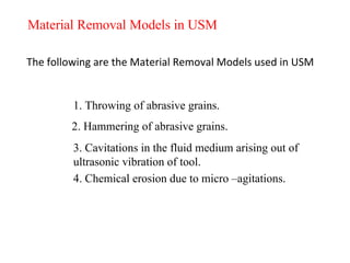
Material Removal Modelsin USM
The following are the Material Removal Models used in USM
1. Throwing of abrasive grains.
2. Hammering of abrasive grains.
3. Cavitations in the fluid medium arising out of
ultrasonic vibration of tool.
4. Chemical erosion due to micro –agitations.
100.
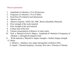
Process parameters
1. Amplitudeof vibration ( 15 to 50 microns)
2. Frequency of vibration ( 19 to 25 kHz).
3. Feed force (F) related to tool dimensions
4. Abrasive size
5. Abrasive material Al203, SiC, B4C, Boron silicarbide, Diamond.
6. Flow strength of the work material
7. Flow strength of the tool material
8. Contact area of the tool
9. Volume concentration of abrasive in water slurry
10. Tool a. Material of tool b. Shape c. Amplitude of vibration d. Frequency of
vibration e. Strength developed in tool
11. Work material a. Material b. Impact strength c. Surface fatigue strength
13. Slurry
a. Abrasive – hardness, size, shape and quantity of abrasive flow
b. Liquid – Chemical property, viscosity, flow rate c. Pressure d. Density
102.
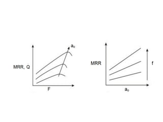
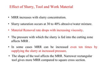
Effect of Slurry,Tool and Work Material
• MRR increases with slurry concentration.
• Slurry saturation occurs at 30 to 40% abrasive/water mixture.
• Material Removal rate drops with increasing viscosity.
• The pressure with which the slurry is fed into the cutting zone
affects MRR .
• In some cases MRR can be increased even ten times by
supplying the slurry at increased pressure.
• The shape of the tool affects the MRR. Narrower rectangular
tool gives more MRR compared to square cross section.
103.
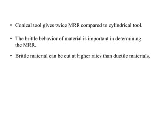
• Conical toolgives twice MRR compared to cylindrical tool.
• The brittle behavior of material is important in determining
the MRR.
• Brittle material can be cut at higher rates than ductile materials.
104.
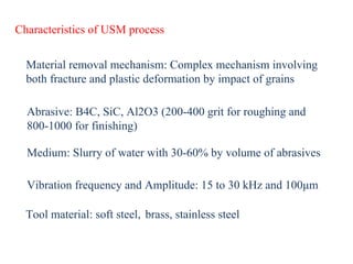
Characteristics of USMprocess
Material removal mechanism: Complex mechanism involving
both fracture and plastic deformation by impact of grains
Abrasive: B4C, SiC, Al2O3 (200-400 grit for roughing and
800-1000 for finishing)
Medium: Slurry of water with 30-60% by volume of abrasives
Vibration frequency and Amplitude: 15 to 30 kHz and 100μm
Tool material: soft steel, brass, stainless steel
105.
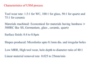
Characteristics of USMprocess
Tool wear rate: 1.5:1 for WC, 100:1 for glass, 50:1 for quartz and
75:1 for ceramic
Surface finish: 0.4 to 0.8μm
Shapes produced: Microholes upto 0.1mm dia. and irregular holes
Low MRR, High tool wear, hole depth to diameter ratio of 40:1
Linear material removal rate 0.025 to 25mm/min
106.
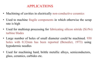
APPLICATIONS
• Machining ofcavities in electrically non-conductive ceramics
• Used to machine fragile components in which otherwise the scrap
rate is high
• Used for multistep processing for fabricating silicon nitride (Si3N4)
turbine blades
• Large number of holes of small diameter could be machined. 930
holes with 0.32mm has been reported (Benedict, 1973) using
hypodermic needles
• Used for machining hard, brittle metallic alloys, semiconductors,
glass, ceramics, carbides etc.
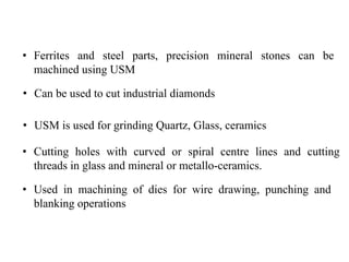
107.
• Ferrites andsteel parts, precision mineral stones can be
machined using USM
• Can be used to cut industrial diamonds
• USM is used for grinding Quartz, Glass, ceramics
• Cutting holes with curved or spiral centre lines and cutting
threads in glass and mineral or metallo-ceramics.
• Used in machining of dies for wire drawing, punching and
blanking operations
108.
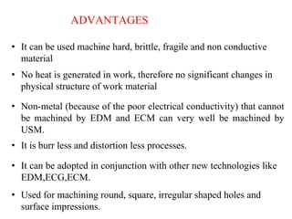
ADVANTAGES
• It canbe used machine hard, brittle, fragile and non conductive
material
• No heat is generated in work, therefore no significant changes in
physical structure of work material
• Non-metal (because of the poor electrical conductivity) that cannot
be machined by EDM and ECM can very well be machined by
USM.
• It is burr less and distortion less processes.
• It can be adopted in conjunction with other new technologies like
EDM,ECG,ECM.
• Used for machining round, square, irregular shaped holes and
surface impressions.
109.
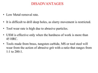
DISADVANTAGES
• Low Metalremoval rate.
• It is difficult to drill deep holes, as slurry movement is restricted.
• Tool wear rate is high due to abrasive particles.
• Tools made from brass, tungsten carbide, MS or tool steel will
wear from the action of abrasive grit with a ratio that ranges from
1:1 to 200:1.
• USM is effective only when the hardness of work is more than
45 HRC.
111.
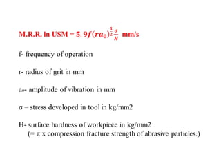
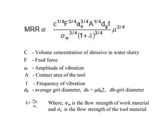
C - Volumeconcentration of abrasive in water slurry
F - Feed force
a0 - Amplitude of vibration
A - Contact area of the tool
f - Frequency of vibration
dg - average grit diameter, db = μdg2, db-grit diameter
112.
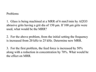
Problems
1. Glass isbeing machined at a MRR of 6 mm3/min by Al2O3
abrasive grits having a grit dia of 150 μm. If 100 μm grits were
used, what would be the MRR?
2. For the above problem, from the initial setting the frequency
is increased from 20 kHz to 25 kHz. Determine new MRR.
3. For the first problem, the feed force is increased by 50%
along with a reduction in concentration by 70%. What would be
the effect on MRR.
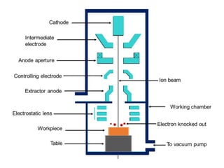
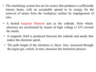
• The machiningsystem has an ion source that produces a sufficiently
intense beam, with an acceptable spread in its energy for the
removal of atoms from the workpiece surface by impingement of
ions.
• A heated tungsten filament acts as the cathode, from which
electrons are accelerated by means of high voltage (1 kV) toward
the anode.
• A magnetic field is produced between the cathode and anode that
makes the electrons spiral.
• The path length of the electrons is, there- fore, increased through
the argon gas, which, in turn, increases the ionization process.
117.
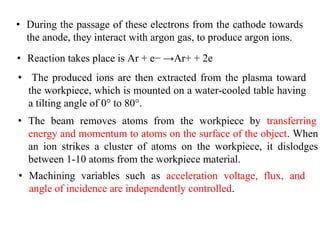
• The producedions are then extracted from the plasma toward
the workpiece, which is mounted on a water-cooled table having
a tilting angle of 0° to 80°.
• Machining variables such as acceleration voltage, flux, and
angle of incidence are independently controlled.
• During the passage of these electrons from the cathode towards
the anode, they interact with argon gas, to produce argon ions.
• Reaction takes place is Ar + e− →Ar+ + 2e
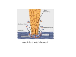
• The beam removes atoms from the workpiece by transferring
energy and momentum to atoms on the surface of the object. When
an ion strikes a cluster of atoms on the workpiece, it dislodges
between 1-10 atoms from the workpiece material.
Applications of IBM:
• It is applied mostly in micro-machining of electronic
components.
• Typical materials that can be etched included glass, alumina,
quartz, crystal, silica, agates, porcelains, numerous metals,
cermets and oxides.
• It is also be used to deposit materials such as platinum,
tungsten and silicon oxide insulators on other material
substrate.
• IBM is used in smoothing of laser mirrors as well as reducing
the thickness of thin films without affecting their surface finish
120.
• Using twoopposing beams, a thin circular region on a rotating
sample can produce samples for transmission electron
microscopy.
• Polishing and shaping of optical surfaces by direct sputtering of
pre- forms in glass, silica, and diamond is performed using
patterning masks.
• The process can produce closely packed textured cones in
different materials including copper, nickel, stainless steel,
silver.
• Atomically clean surfaces can be produced by IBM that are
used in the adhesion of gold films to silicon and aluminum
oxide
121.
Advantages of IBM:
• The IBM is used as a micro- and nano-machining tool, to modify
or machine materials at the micro- and nanoscale.
• IBM tools are designed to etch or machine surfaces, an ideal FIB
might machine away one atom layer without any disruption of the
atoms in the next layer, or any residual disruptions above the
surface.
• The IBM is also commonly used to prepare samples for the
transmission electron microscope
• IBM is also used for maskless implantation
• Other techniques, such as ion milling or electropolishing can be
used to prepare such thin samples.
122.
Disadvantages of IBM
•High capital equipment cost
• Long production time due to the time needed to generate a
vacuum
• The presence of a thin recast layer
• Need for auxiliary backing material
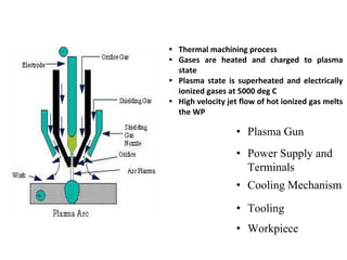
• Plasma Gun
•Power Supply and
Terminals
• Cooling Mechanism
• Tooling
• Workpiece
• Thermal machining process
• Gases are heated and charged to plasma
state
• Plasma state is superheated and electrically
ionized gases at 5000 deg C
• High velocity jet flow of hot ionized gas melts
the WP
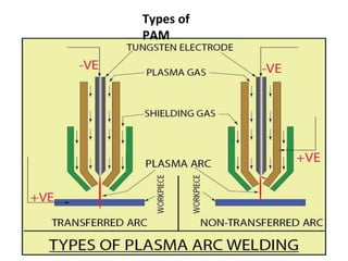
Process parameters
Parameters thatgovern the performance of PAM can be divided
into three categories:
1. Those associated with the design and operation of the torch
• electrical power delivered,
• the gases used to form the plasma,
• the flow rate of the gases through the torch,
• the orifice diameter through the nozzle duct
2. Those associated with the physical configuration of the set up
• torch standoff,
• angle to the work,
• depth of cut,
• feed into the work
127.
3. Environment inwhich the work is performed
• cooling that is done on the bar,
• any protective type of atmosphere used to reduce oxidation for
the exposed high temperature machined surface and any means
that might be utilized to spread out or deflect the arc and plasma
impingement area
128.
Metal Removal rateof
PAM
• MRR increases with current, but depends on cutting speed, gas flow rate, thickness of
work.
• Higher the value of cutting speed more the MRR
• Cutting speed depends on the thickness of WP, and material properties and surface
speed of work
• Voltage depends on the ionization voltage and gas flow
Heat Affected zone (HAZ) of PAM
• The depth of HAZ is approximately 0.75 mm
• HAZ is the function of thickness of WP, plasma arc system and material type
129.
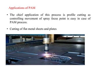
Applications of PAM
•The chief application of this process is profile cutting as
controlling movement of spray focus point is easy in case of
PAM process.
• Cutting of flat metal sheets and plates
130.
Advantages of PAM
•It gives faster production rate.
• Very hard and brittle metals can be machined.
• Small cavities can be machined with good dimensional
accuracy
• The plasma arc can be used to cut any metal or even to
non-conducting materials like concrete etc., since it is
primarily a melting process
• Smooth cuts free from contaminants are obtained in the
process
• Operating costs are less when compared to oxy-fuel torch
• Can be automated
131.
Disadvantages of PAMProcess
• Its initial cost is very high.
• The process requires over safety precautions which further
enhance the initial cost of the setup.
• Some of the workpiece materials are very much prone to
metallurgical changes on excessive heating so this fact
imposes limitations to this process.
• It is uneconomical for bigger cavities to be machined.
• Smoke and noise
• Sharp corners are difficult to produce because of the wide
diameter of the plasma stream
• Burr is often produced
• Taper on the workpiece may occur
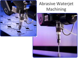
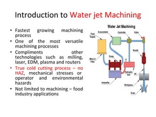
Introduction to Waterjet Machining
• Fastest growing machining
process
• One of the most versatile
machining processes
• Compliments other
technologies such as milling,
laser, EDM, plasma and routers
• True cold cutting process – no
HAZ, mechanical stresses or
operator and environmental
hazards
• Not limited to machining – food
industry applications
134.
Pure WJ Cutting
•Pure cuts soft materials – corrugated cardboard,
disposable diapers, tissue papers, automotive interiors
• Very thin stream (0.004-0.010 dia)
• Extremely detailed geometry
• Very little material loss due to cutting
• Can cut thick, soft, light materials like fiberglass
insulation up to 24” thick or thin, fragile materials
• Very low cutting forces and simple fixturing
• Water jet erodes work at kerf line into small particles
135.
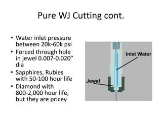
Pure WJ Cuttingcont.
• Water inlet pressure
between 20k-60k psi
• Forced through hole
in jewel 0.007-0.020”
dia
• Sapphires, Rubies
with 50-100 hour life
• Diamond with
800-2,000 hour life,
but they are pricey
136.
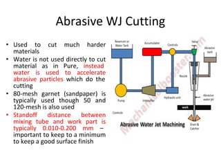
Abrasive WJ Cutting
•Used to cut much harder
materials
• Water is not used directly to cut
material as in Pure, instead
water is used to accelerate
abrasive particles which do the
cutting
• 80-mesh garnet (sandpaper) is
typically used though 50 and
120-mesh is also used
• Standoff distance between
mixing tube and work part is
typically 0.010-0.200 mm –
important to keep to a minimum
to keep a good surface finish
137.
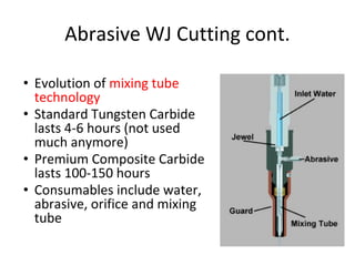
Abrasive WJ Cuttingcont.
• Evolution of mixing tube
technology
• Standard Tungsten Carbide
lasts 4-6 hours (not used
much anymore)
• Premium Composite Carbide
lasts 100-150 hours
• Consumables include water,
abrasive, orifice and mixing
tube
138.
Tolerances
• Typically +/-0.005 inch
• Machines usually have repeatability of 0.001
inch
• Comparatively traditional machining centers
can hold tolerances 0f 0.0001 inch with similar
repeatability
• WJ tolerance range is good for many
applications where critical tolerances are not
crucial to workpart design
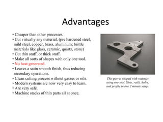
Advantages
• Cheaper thanother processes.
• Cut virtually any material. (pre hardened steel,
mild steel, copper, brass, aluminum; brittle
materials like glass, ceramic, quartz, stone)
• Cut thin stuff, or thick stuff.
• Make all sorts of shapes with only one tool.
• No heat generated.
• Leaves a satin smooth finish, thus reducing
secondary operations.
• Clean cutting process without gasses or oils.
• Modern systems are now very easy to learn.
• Are very safe.
• Machine stacks of thin parts all at once.
This part is shaped with waterjet
using one tool. Slots, radii, holes,
and profile in one 2 minute setup.
141.
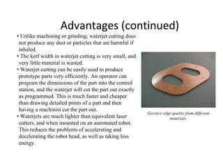
Advantages (continued)
• Unlikemachining or grinding, waterjet cutting does
not produce any dust or particles that are harmful if
inhaled.
• The kerf width in waterjet cutting is very small, and
very little material is wasted.
• Waterjet cutting can be easily used to produce
prototype parts very efficiently. An operator can
program the dimensions of the part into the control
station, and the waterjet will cut the part out exactly
as programmed. This is much faster and cheaper
than drawing detailed prints of a part and then
having a machinist cut the part out.
• Waterjets are much lighter than equivalent laser
cutters, and when mounted on an automated robot.
This reduces the problems of accelerating and
decelerating the robot head, as well as taking less
energy.
Get nice edge quality from different
materials.
142.
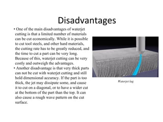
Disadvantages
• One ofthe main disadvantages of waterjet
cutting is that a limited number of materials
can be cut economically. While it is possible
to cut tool steels, and other hard materials,
the cutting rate has to be greatly reduced, and
the time to cut a part can be very long.
Because of this, waterjet cutting can be very
costly and outweigh the advantages.
• Another disadvantage is that very thick parts
can not be cut with waterjet cutting and still
hold dimensional accuracy. If the part is too
thick, the jet may dissipate some, and cause
it to cut on a diagonal, or to have a wider cut
at the bottom of the part than the top. It can
also cause a rough wave pattern on the cut
surface.
Waterjet lag
143.
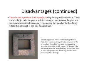
Disadvantages (continued)
• Taperis also a problem with waterjet cutting in very thick materials. Taper
is when the jet exits the part at a different angle than it enters the part, and
can cause dimensional inaccuracy. Decreasing the speed of the head may
reduce this, although it can still be a problem.
Stream lag caused inside corner damage to this
1-in.-thick stainless steel part. The exit point of the
stream lags behind the entrance point, causing
irregularities on the inside corners of the part. The
thicker the material is or the faster an operator tries
to cut it, the greater the stream lag and the more
pronounced the damage.
144.
Waterjets vs. Lasers
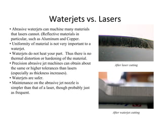
•Abrasive waterjets can machine many materials
that lasers cannot. (Reflective materials in
particular, such as Aluminum and Copper.
• Uniformity of material is not very important to a
waterjet.
• Waterjets do not heat your part. Thus there is no
thermal distortion or hardening of the material.
• Precision abrasive jet machines can obtain about
the same or higher tolerances than lasers
(especially as thickness increases).
• Waterjets are safer.
• Maintenance on the abrasive jet nozzle is
simpler than that of a laser, though probably just
as frequent.
After laser cutting
After waterjet cutting
145.
Waterjets vs. EDM
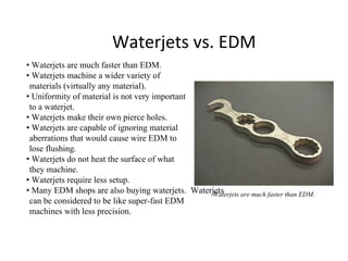
•Waterjets are much faster than EDM.
• Waterjets machine a wider variety of
materials (virtually any material).
• Uniformity of material is not very important
to a waterjet.
• Waterjets make their own pierce holes.
• Waterjets are capable of ignoring material
aberrations that would cause wire EDM to
lose flushing.
• Waterjets do not heat the surface of what
they machine.
• Waterjets require less setup.
• Many EDM shops are also buying waterjets. Waterjets
can be considered to be like super-fast EDM
machines with less precision.
Waterjets are much faster than EDM.
146.
Waterjets vs. Plasma
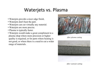
•Waterjets provide a nicer edge finish.
• Waterjets don't heat the part.
• Waterjets can cut virtually any material.
• Waterjets are more precise.
• Plasma is typically faster.
• Waterjets would make a great compliment to a
plasma shop where more precision or higher
quality is required, or for parts where heating is
not good, or where there is a need to cut a wider
range of materials.
After plasma cutting
After waterjet cutting
Conclusion
• Relatively newtechnology has caught on quickly
and is replacing century-old methods for
manufacturing
• Used not only in typical machining applications,
but food and soft-goods industries
• As material and pump technology advances faster
cutting rates, longer component life and tighter
tolerances will be achievable
• Paves the way for new machining processes that
embrace simplicity and have a small
environmental impact

![MRR for RC circuited EDM
V = V0
(1-e –t/RC
)
V= 0.7 V0
-0.9 V0
Frequency of spark, f = 1/tc
= ________1___________
RC loge
[ V0
/ (V0
-Vd)]
The energy released per spark is given by E = 0.5 (C Vd
2
)
Power consumed , W= 0.5 (C Vd
2
) x frequency of sparking
Q = 27.4 W 1. 54
, where Q is the removal rate in mm3
/min and W is the power
input kw.
Q = K 0.5 (C Vd
2
) f
For steel](https://image.slidesharecdn.com/module3-250505080324-20ad882f/85/Advanced-manufacturing-engineering-non-conventional-machining-35-320.jpg)