Download to read offline
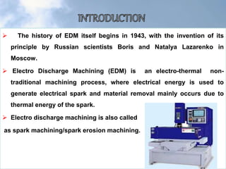
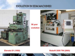
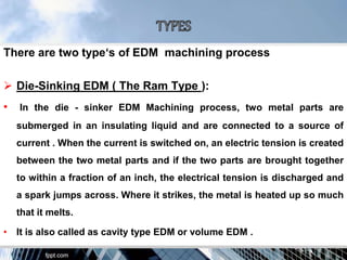
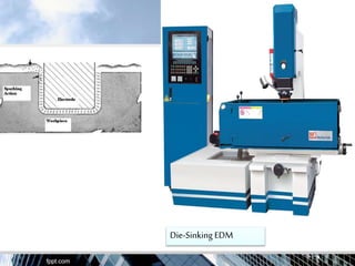
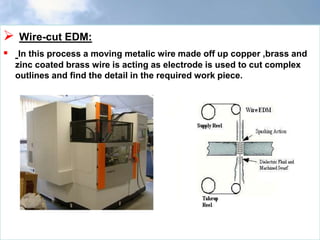
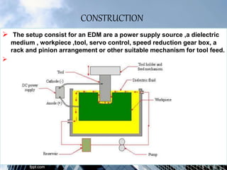
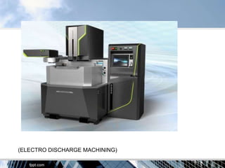
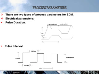


This document summarizes electro discharge machining (EDM). EDM was invented in 1943 and uses electrical sparks to remove material from a conductive workpiece. There are two main types: die-sinking EDM and wire-cut EDM. The document discusses the construction, working principle, tool materials, dielectrics used, machining ratios, process parameters, advantages, and applications of EDM for complex shapes and hard materials.


![Electrical discharge machining [EDM]](https://cdn.slidesharecdn.com/ss_thumbnails/electricaldischargemachiningedm-170803232011-thumbnail.jpg?width=640&height=640&fit=bounds)


