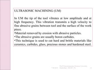
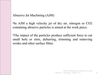
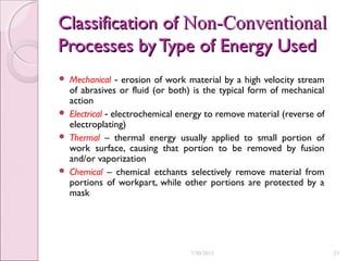
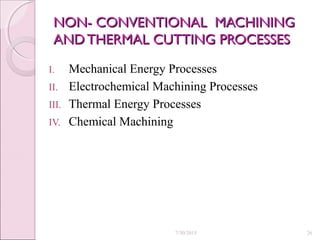
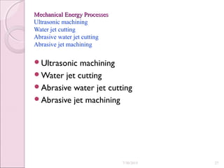
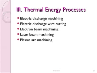
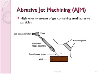
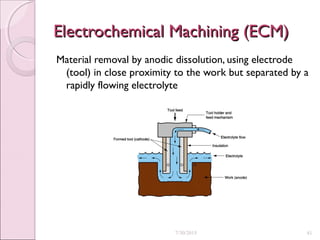
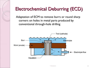
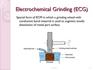
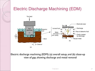
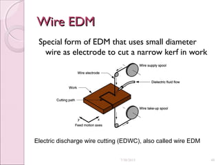
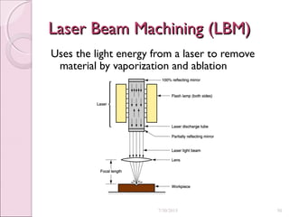
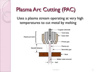
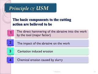
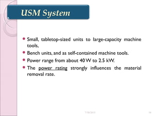
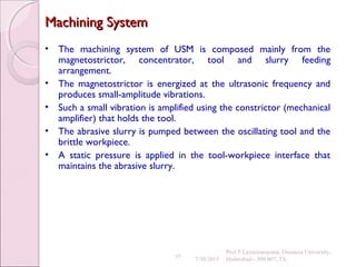
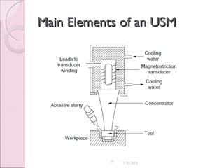
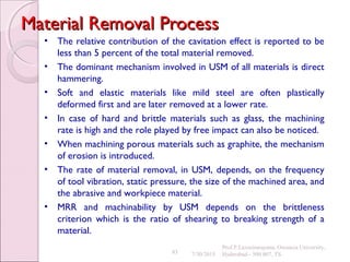
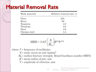
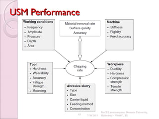
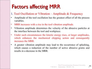
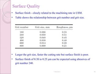
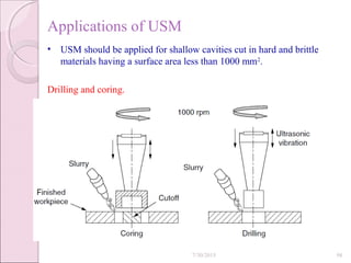
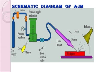
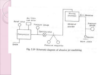
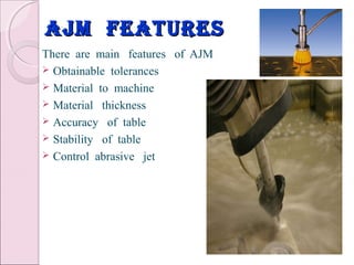
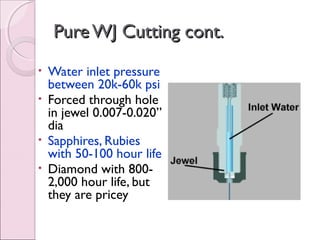
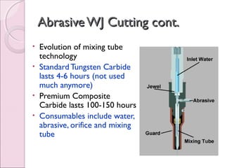
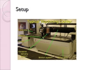
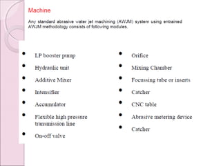
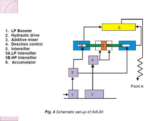
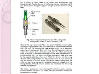
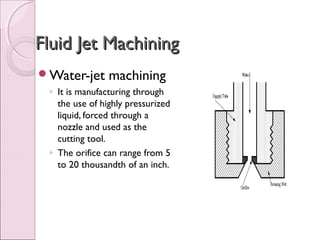
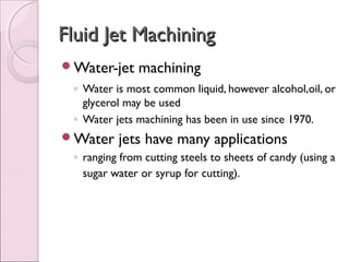
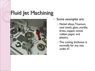
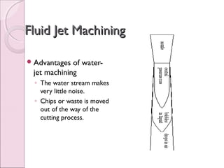
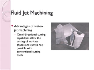
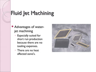
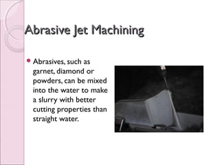
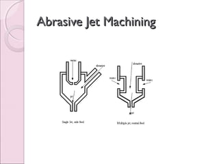
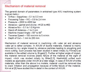
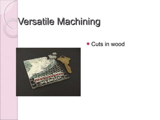
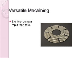
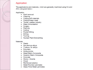
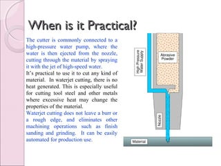
This document discusses conventional and non-conventional machining methods. It begins by defining conventional machining as using a sharp cutting tool for removal of metal. Non-conventional machining does not require physical contact between tool and workpiece and instead uses tools like laser beams or water jets. The document then covers several non-conventional machining processes in more detail like ultrasonic machining, abrasive jet machining, and water jet machining. It concludes by comparing characteristics of conventional and non-conventional machining.
Nontraditional machining processes like waterjet machining (WJM) and abrasive waterjet machining (AWJM) use mechanical energy from water and abrasives for material removal. WJM is used for softer materials while AWJM can machine harder materials. AWJM has advantages over traditional machining like fast setup, low heat generation, and ability to machine complex shapes. Parameters like orifice size, water pressure, abrasive type and flow rate, and traverse speed need to be optimized for effective AWJM.
Non conventional machining process - me III - 116010319119Satish Patel
Â
This document discusses non-conventional machining processes and abrasive water jet cutting. It classifies non-conventional processes into thermal and electro-thermal, mechanical, and chemical and electro-chemical processes. It then describes abrasive water jet cutting, where a high pressure water jet mixed with abrasive particles is used to cut materials. Advantages include the ability to cut hard and brittle materials without generating heat, while disadvantages include low material removal rates and abrasive particles embedding in the workpiece.
This document provides an overview of 4 unconventional machining processes: abrasive jet machining, water jet machining, abrasive water jet machining, and ultrasonic machining. For each process, it describes the basic working principles, key process parameters, advantages, disadvantages, and applications. The processes remove material using abrasive particles accelerated by air, water, or ultrasonic vibration rather than traditional cutting tools. Water jet machining can cut a variety of materials with no heat effect, while adding abrasives allows cutting stronger metals. Ultrasonic machining uses tool vibration to erode material with abrasives and can machine hard, brittle materials.
Non-traditional machining processes are used to manufacture complex precision parts. They use indirect energy like sparks, lasers, heat or chemicals instead of direct tool contact. This allows machining of hard materials with complex shapes. Some common non-traditional processes include electrical discharge machining (EDM), electrochemical machining (ECM), laser beam machining, and abrasive jet machining. These processes remove material using techniques like electrical sparks, electrolysis, focused laser beams or high pressure abrasive jets. Non-traditional machining provides benefits like high accuracy, improved surface finish, less tool wear and greater design flexibility compared to traditional machining.
This document provides an introduction to electrical discharge machining (EDM). EDM is an unconventional machining process where material is removed by electric sparks between an electrode tool and conductive workpiece, with no direct contact between them. Key aspects of EDM covered include the construction of EDM machines, the role of dielectric fluids, factors that affect the material removal rate such as capacitance and spark parameters, and electrode tool materials and wear characteristics. Graphite, copper, and copper-tungsten are commonly used as tool materials in EDM due to properties like machinability and erosion resistance.
This document provides information on non-traditional manufacturing processes. It defines non-traditional processes as those that remove material using mechanical, thermal, electrical or chemical energy without direct tool-workpiece contact. Several non-traditional processes are described in detail, including ultrasonic machining, water jet machining, abrasive jet machining, electrochemical grinding, and chemical milling. Non-traditional processes allow hard and brittle materials to be machined without damage and with better surface finish compared to traditional processes. They find applications in industries such as aerospace, electronics, and automotive.
Non-traditional manufacturing processes is defined as a group of processes that remove excess material by various techniques involving mechanical, thermal, electrical or chemical energy or combinations of these energies
1. The document discusses advanced machining processes and provides an overview of conventional and non-conventional machining.
2. Non-conventional machining uses techniques other than traditional cutting tools, such as thermal, electrical, chemical energies. Examples covered include abrasive jet machining, electrochemical machining, and electron beam machining.
3. Key characteristics of non-conventional machining are that material can be removed without chip formation, there may not be a physical tool, and the tool need not be harder than the workpiece.
Unconventional machining processes remove metal without direct contact between the tool and workpiece. They were developed to address the limitations of conventional machining, such as waste disposal, heat generation, and difficulty machining hard or complex materials. Some unconventional processes include metal forming techniques that shape metals using high energy inputs in short time intervals. Selection of unconventional machining involves considering physical parameters, part shapes, process capabilities, and cost. While unconventional machining enables new applications, it also has limitations such as higher costs and slower speeds than conventional techniques.
The document discusses non-conventional machining processes. It begins by distinguishing between conventional machining processes, which use hard cutting tools to remove material, and non-conventional processes, which use other energies like mechanical, thermal, electrical, or chemical. Non-conventional processes are then classified based on the type of energy used, including mechanical, electrochemical, electro-thermal, and chemical processes. Examples of specific non-conventional machining techniques are provided within each classification.
The document provides an overview of non-traditional machining (NTM) processes, including:
- The need for NTM processes due to limitations of conventional machining processes.
- A classification of NTM processes into mechanical, electrical, thermal, chemical, and hybrid categories.
- Descriptions of various NTM processes like EDM, LBM, ECM, discussing their operating parameters, material removal mechanisms, applications, advantages, and limitations.
- Comparisons of NTM processes in terms of suitable materials, achievable shapes, and process variants.
This document is a seminar report on non-conventional machining processes submitted by Rahul Solanki for their master's degree. It discusses several non-traditional machining techniques including abrasive jet machining, ultrasonic machining, water jet cutting, abrasive water jet cutting, and electrical discharge machining. For each technique, it describes the basic working principles, applications, advantages, and limitations. The report provides an overview of different options for machining hard materials and complex shapes that are difficult with traditional methods.
This document provides an overview of several non-traditional machining processes including abrasive grinding, ultrasonic machining, abrasive water jet machining, chemical machining, electro-chemical machining, electro-discharge machining, and laser beam machining. It describes the basic mechanisms and applications of each process. Key details include that abrasive grinding can provide a fine finish but has low material removal rates, ultrasonic machining uses abrasive slurries to erode brittle materials, abrasive water jet cutting can cut extremely thick materials but thickness affects cutting speed, and electro-discharge machining uses sparking to erode materials in the shape of a graphite tool electrode.
This document discusses various nontraditional machining and thermal cutting processes. It begins by defining these processes as those that remove material using mechanical, thermal, electrical, or chemical energy without a conventional cutting tool. These alternative processes are important for machining new metals and non-metals, producing complex geometries, and avoiding surface damage from traditional methods. The document then groups and describes various nontraditional processes including mechanical (ultrasonic machining, water jet cutting), electrochemical (electrochemical machining), thermal (electric discharge machining, laser beam machining), and chemical (chemical milling) processes.
Modern manufacturing has seen the development of harder materials that are difficult to machine using conventional methods. This has driven the creation of unconventional machining methods that use various forms of energy without physical contact between tool and workpiece. Some key unconventional methods are electrical discharge machining, electrochemical machining, laser beam machining, and abrasive jet machining. These methods allow machining of any material, produce less tool wear and residual stress, and enable intricate shaping. However, they are generally more costly and have limitations such as requiring electrically conductive materials. Overall, unconventional machining methods expand what is possible in modern manufacturing.
This document discusses advanced machining processes, which utilize chemical, electrical, or high-energy beams to remove material as they are needed for difficult-to-machine materials or complex part geometries. It introduces various advanced processes like chemical machining, electrochemical machining, electrical discharge machining, laser beam machining, electron beam machining, and others. These processes allow machining of very hard materials, brittle materials, or parts that are too small, complex, or fragile for traditional machining techniques.
This document provides an overview of unconventional machining processes. It begins by defining conventional machining and its limitations in machining complex geometries and hard materials. Unconventional machining uses indirect energy sources like sparks, heat, or chemicals instead of direct tool contact. The document then discusses various unconventional processes like EDM, laser beam machining, water jet machining, and their characteristics. It classifies unconventional processes and provides details on electrochemical machining, electrochemical grinding, and ultrasonic machining. In closing, it acknowledges the development of these nontraditional techniques for precision manufacturing applications.
Production Techniques 2 - advanced machining techniques reportKerrie Noble
Â
This document compares and contrasts four advanced machining processes: photo-chemical machining, electrical-discharge machining, laser-beam machining, and electro-chemical machining. It discusses the process capabilities and design considerations for each. Two case studies are presented on using electro-chemical machining for a biomedical implant and manufacturing small satellites. The document concludes that each process has strengths for different applications in industries like aerospace, electronics, automotive, and medical.
This document provides an overview of unconventional machining processes. It begins with an introduction to conventional machining processes and then discusses the need for unconventional processes to machine advanced materials. The document categorizes unconventional processes as mechanical, electrical, chemical/electrochemical, or thermal based. Specific unconventional processes like ultrasonic machining and abrasive water jet cutting are then described in more detail.
Advanced Machining Processes by Himanshu VaidHimanshu Vaid
Â
Electrochemical machining uses an electrolyte and electrical current to remove metal atoms, allowing it to machine complex cavities in high-strength materials with a burr-free surface unaffected by material properties. Electrochemical grinding also uses an electrolyte but with an abrasive rotating cathode, resulting in very low tool wear suitable for honing. Electrical-discharge wire cutting removes material like a band saw using a dielectric fluid and inexpensive wire. Laser beam machining vaporizes material with a concentrated light beam but produces a rough, heat-affected surface best for small holes. Plasma arc cutting also rapidly vaporizes material for higher material removal rates and good surface finish over small widths.
This document discusses advanced machining processes, which utilize chemical, electrical, or high-energy beams to machine materials that cannot be processed through traditional machining methods. It describes 10 common types of advanced machining, including chemical machining, electrochemical machining, electrical discharge machining, laser beam machining, electron beam machining, plasma arc cutting, ultrasonic machining, water jet machining, abrasive jet machining, and nanofabrication methods. The document explains the need for these advanced processes and provides examples of typical parts machined through these methods.
Non Traditional Machining is playing vital role in now a days in mechanical Industries so student it should be need sound knowledge in this particular subject due to impact of this subject i am prepare in this materials it is most useful for my students...
All The Best ...
By: Author-Prof.S.Sathishkumar
This document provides an overview of various advanced machining processes, including chemical milling, photochemical blanking, electrochemical machining, electrical discharge machining, laser beam machining, electron beam machining, plasma arc cutting, water jet machining, abrasive water jet machining, and abrasive jet machining. Each process is described along with considerations for its application. These non-traditional machining methods allow complex shapes to be cut in hard materials and offer alternatives to conventional processes for difficult-to-machine materials.
This document provides an overview of various unconventional machining processes including abrasive jet machining (AJM), laser beam machining (LBM), electro-discharge machining (EDM), and ultrasonic machining (USM). It defines each process, explains their working principles, typical parameters used, applications, advantages, and limitations. AJM uses a high-speed stream of abrasive particles to erode material from the workpiece. LBM utilizes a high-power laser beam to melt and vaporize workpiece material. EDM involves sparking between an electrode tool and workpiece submerged in a dielectric liquid to thermally erode material. USM vibrates an abrasive tool at ultrasonic frequencies
Advantages and limitation of non traditional machiningMrunal Mohadikar
Â
The document provides an overview of several non-traditional machining processes including Electrical Discharge Machining (EDM), Electrochemical Machining (ECM), Ultrasonic Machining (USM), Laser Beam Machining (LBM), Water Jet Cutting, and Abrasive Water Jet Cutting. For each process, the document discusses the basic technique, key advantages such as ability to machine hard materials and produce complex shapes, and limitations such as low material removal rates or inability to machine non-conductive materials. The document serves to educate readers on alternative manufacturing methods beyond traditional cutting tools and their various applications and constraints.
This document discusses various nontraditional machining and thermal cutting processes. It begins by defining these processes as those that remove material using mechanical, thermal, electrical, or chemical energy without a conventional cutting tool. These alternative processes are important for machining new metals and non-metals, producing complex geometries, and avoiding surface damage from traditional methods. The document then groups and describes various nontraditional processes including mechanical (ultrasonic machining, water jet cutting), electrochemical (electrochemical machining), thermal (electric discharge machining, laser beam machining), and chemical (chemical milling) processes.
This document provides an overview of non-conventional machining processes including ultrasonic machining, water jet machining, electro-chemical machining, electro-chemical grinding, and electrical discharge machining. The objective is to make audiences aware of the merits of these non-conventional processes over traditional machining for machining complex, less machinable, or brittle materials in a faster and more economical way using computer-controlled processes with minimal human intervention. An outline and brief description is given for each non-conventional machining technique.
The document discusses various unconventional machining processes. It begins with introducing that unconventional machining uses indirect energy like sparks, heat or chemicals rather than direct contact between a tool and workpiece. It then covers different unconventional processes like EDM, laser beam machining, electrochemical machining and their characteristics. The document categorizes unconventional machining processes and provides details on processes like chemical machining, electrochemical grinding and ultrasonic machining. It concludes with discussing advantages and disadvantages of non-conventional machining.
The document discusses non-conventional machining processes, specifically electric discharge machining (EDM). EDM uses electric sparks to thermally remove metal from a workpiece without contact between the tool and workpiece. There are several types of EDM including ram EDM, wire EDM, and small hole EDM. EDM can machine hard materials, achieve high accuracy and surface finish, and is widely used for dies, aerospace parts, and medical devices. While offering advantages over traditional machining, EDM also has limitations such as low material removal rates and electrode wear.
Conventional machining involves physically removing material from a workpiece using a harder cutting tool, typically through mechanical forces. Non-conventional machining utilizes other forms of energy like thermal, chemical, or electrical instead of mechanical forces and may not require physical contact or chip formation. While conventional machining can be used for most materials economically, non-conventional machining allows for higher precision machining of hard metals and complex parts but requires more advanced equipment and skilled operators.
This document summarizes an automated system for magnetic particle inspection of railway wheels. The system uses magnetic particles and high resolution digital cameras to detect surface cracks as small as 1mm in length. It magnetizes the wheel using coils, then coats it with fluorescent particles. Defects are visible under ultraviolet light and scanned by a digital camera. Signal processing techniques are used to detect flaws and separate them from noise. The automated system allows for highly reliable inspection to prevent railway accidents.
This document provides information about solar panels, batteries, water tanks, motors, and pumps. It describes the basic components and workings of solar panels and explains how individual solar cells are connected in series to produce higher voltages. It lists the key parameters to consider for water tanks, including location, volume, purpose, temperature, and delivery pressure requirements. It also provides specifications for motors, describing how they convert electrical to mechanical energy. Finally, it outlines different types of pumps based on how they impart energy to fluids and lists common rating and material specifications.
The document outlines topics to discuss regarding 3D vision technology, including a brief history. It covers early patents from 1880 and the first 3D movie from 1922. Methods of capturing 3D images are discussed as well as techniques for projection, such as anaglyph, polarization, interference filters, and Dolby 3D. The document also touches on classifying 3D formats and modern technologies that enable 3D without glasses, like autostereoscopic screens and holograms. References are provided at the end.
High cutting temperatures during machining can negatively impact both the tool and workpiece. Temperatures as high as 6000C are generated at the tool-chip interface, leading to rapid tool wear, hot chips that pose safety risks, and dimensional inaccuracies in the workpiece. The majority of the heat is carried away by the chips, with 10-20% absorbed by the tool and some by the workpiece. Efforts should be made to ensure that chips remove as much heat as possible to minimize tool and workpiece damage.
The document presents a project on developing a portable mini lathe. A group of 6 students led by Sujith R. are developing the lathe under the guidance of their professor. The portable mini lathe will address issues with conventional lathes like bulkiness and fixed location. It will allow for turning, grinding, cutting, and polishing of wood and light metals within a workshop. The lathe's key components include a hand drill as the headstock, wooden bed and tailstock, and scissor jack mechanism for compactness. The lathe is designed for portability, low cost, and enabling basic machining by carpenters using workshop tools.
Flame cutting, also known as oxy-fuel gas cutting, uses a cutting torch to direct a jet of oxygen at a metal surface preheated to ignition temperature by an oxy-acetylene flame. The oxygen reacts with the metal to form metal oxide, which is blown away by the jet, cutting through the metal. Plasma arc cutting improves on flame cutting by using a constricted electric arc and jet of ionized gas to both melt and remove the metal, allowing it to cut a wider variety of metals faster and with a narrower kerf. Both methods can cut ferrous metals but flame cutting is limited while plasma arc cutting can cut any metal.
Mechanical cutting involves splitting a workpiece into two by removing a thin slice of material. The key processes are sawing using hacksaws, bandsaws, and circular saws. Hand shears use one hand to snip and collect while long blades make them versatile. Bench shears are mounted and have a lever mechanism to increase force but cannot do delicate work. Guillotines use a heavy sliding blade for beheading. Shear machines cut stock without chips using straight or curved blades for sheet metal. Nibblers cut sheet metal with minimal distortion using punch and die or scissor-like mechanisms. Bench shears can normally cut up to 0.5mm thick mild steel.
Introduction to Sure NDT, a third-party specialist inspection and testing company for the oil and gas industry providing a comprehensive integrated scope of inspection, repair and maintenance services.
Based in Bangkok and Songkhla in Thailand we have the ability to cover projects nationally, regionally and Worldwide.
Sure NDT also operates a training division with unique industry based competency and safety training division.
Theory of-metal-cutting-120730021018-phpapp01manojkumarg1990
Â
This document contains lecture notes on manufacturing processes and machine tools. It begins with definitions of manufacturing and discusses how raw materials are converted into finished products through various processes. It then classifies manufacturing processes into categories like casting, forming, machining, joining, surface treatments, and heat treating. The notes explain manufacturing systems and production systems. It also covers topics like machining parameters, cutting speeds and feeds, cutting tools and materials, and provides examples of machining processes and applications.
This is an overview of thermal metal removal processes under non conventional machining. this includes EDM, IBM, PAM, LBM, EBM .
Check this out, could be helpful!
This design report proposes an evaporative cooling system with LED lighting for small shops. It will use a solar panel to charge a battery and power a water pump, fan, and LEDs. An evaporative cooling process lowers the air temperature by passing it through wet pads. The proposed design includes a solar charger, evaporative cooling fan, LED lighting, airflow control switch, battery, and AC/DC charging options. It is intended to provide cooling and lighting for shop owners in areas with unreliable electricity access.
Laser Beam Manufacturing- Non Conventional machining Hany G. Amer
Â
Laser beam manufacturing is used for manufacturing difficult parts that cant be done using conventional machining methods.
This ppt covers the advantages and disadvantages of using LBM.
Non-traditional machining techniques remove material using various energy sources besides traditional cutting tools. They are divided into mechanical, electrical, thermal, and chemical techniques. Non-traditional techniques are needed for hard or complex materials, and can machine intricate shapes and deep holes. Selection depends on the part geometry, material properties, machining capabilities, and cost effectiveness. While more expensive initially than traditional techniques, non-traditional machining offers higher precision, surface finish, and ability to machine difficult materials.
This document discusses electric discharge machining (EDM), including its principle of operation, mechanism of metal removal, and classification of spark erosion processes. EDM is a thermal machining process that uses electric sparks to erode material from a workpiece by electric spark erosion. In the EDM process, an electric spark is used as a cutting tool to cut the workpiece to the desired shape. The sparks generate extreme heat between 8,000-12,000°C which causes fusion or vaporization of metal at the discharge point, removing tiny amounts and creating craters that shape the workpiece. There are different classifications of spark erosion processes including sinking, cutting, and grinding by EDM.
The document discusses theories of metal machining and chip formation. It describes how early theories like the theory of tear and theory of compression were later disproven. The generally accepted theory today is the theory of shear, which proposes that metal cutting occurs through shear along a plane at an angle to the cutting direction. The document also outlines the difficulties in studying metal cutting processes and how orthogonal cutting experiments were developed to simplify the analysis.
This document provides an overview of unconventional machining processes (UMP) compiled by Dr. B. Ramesh. It begins by defining the key differences between unconventional and conventional machining. It then discusses factors to consider when selecting a UMP and provides tables comparing various processes. The document focuses on mechanical energy-based processes like abrasive jet machining (AJM) and ultrasonic machining (USM), explaining their principles, parameters, advantages, and applications. It also briefly covers water jet machining and abrasives used in different UMPs.
IRJET- Advance Manufacturing Processes Review Part IIRJET Journal
Â
1. The document discusses several advanced manufacturing processes including abrasive jet machining, ultrasonic machining, water jet machining, electrochemical machining, electro-discharge machining, and laser beam machining.
2. These non-traditional machining processes use energy-based techniques like mechanical, thermal, electrical, or chemical energy instead of traditional cutting tools to remove material.
3. The advanced processes allow for machining of extremely hard materials, complex shapes, high accuracy, and are not limited by workpiece hardness like traditional machining.
This seminar presentation discusses conventional and non-conventional machining processes. It begins by dividing manufacturing processes into primary and secondary processes and further dividing material removal processes into conventional and non-conventional machining. Common conventional processes are described as turning, milling, and grinding. Non-conventional processes are defined as using thermal, chemical, or electrical energy and examples provided include EDM, laser beam machining, and ultrasonic machining. The presentation then compares conventional and non-conventional machining, describing advantages of non-conventional such as better accuracy and surface finish for hard materials where conventional machining is difficult.
The document discusses conventional and unconventional machining processes. Conventional machining involves direct contact between the tool and workpiece and removal of metal through chip formation, which produces chips as waste. Unconventional processes do not require direct contact and instead use various forms of energy like thermal, electrical or electrochemical to remove metal. Common unconventional processes described include EDM, ECM, laser beam machining and water jet machining. The document also covers CNC machines and how part programs control automated machining through coded G and M commands.
This document provides an overview of unconventional machining processes (UCM). It discusses the need for UCM due to limitations of conventional machining. UCM is classified based on the energy used and mechanism. Examples of processes include mechanical (AWJM, USM), electrical (EDM, WEDM), chemical/electrochemical (ECM, ECG), and thermal (LBM, PAM, EBM). Selection of a UCM process depends on the workpiece parameters, shape, capability, and economic considerations. The document provides details on the working principles, equipment, parameters, finishes, and applications of different UCM processes.
This document provides an overview of advanced machining processes, also known as unconventional or non-traditional machining. It begins with an introduction and outlines the course objectives to understand these processes and their advantages over conventional techniques. These processes are classified based on the type of energy used, including mechanical, electrical, chemical/electro-chemical, and thermal. Examples of specific processes are described within each category, such as abrasive jet machining, electrical discharge machining, electrochemical machining, and laser beam machining. Diagrams are provided to illustrate key principles and applications for several of the machining methods.
This document provides an overview of material removal processes, also known as subtractive manufacturing. It discusses turning, milling, and drilling operations as the three principal machining processes. It also covers cutting tool materials, cutting fluids, and machining processes for producing various shapes such as round, cylindrical, and irregular shapes. The document discusses factors like environmental safety, accuracy, cost effectiveness, and advantages and disadvantages of machining processes.
Introduction to Unconventional Machining Processeslaxtwinsme
Â
The document discusses conventional and unconventional machining processes, describing characteristics of each such as chip formation, tool-workpiece contact, accuracy, and energy domains involved. It classifies unconventional machining processes into categories based on the type of energy used like mechanical, thermal, electrical, or chemical. Examples are provided for each category and factors for selecting the appropriate machining process are outlined.
1) The document describes the design and development of a forging hammer machine. The machine is intended to replace manual hammering and increase efficiency in forging processes.
2) The forging hammer machine is designed to have a hammer that is powered by a motor and pedal system to perform automated hammering. The hammer will provide repetitive blows to shape metal between dies.
3) Testing of the forging hammer machine showed that it can reduce the time and effort required for hammering processes compared to manual hammering. The machine also allows for a more consistent and operator-independent hammering process.
Modern Manufacturing Technology
The document discusses modern, unconventional machining methods that have emerged over the past 50 years to address difficulties in machining harder metals and alloys using conventional methods. Unconventional methods remove material without mechanical contact using various forms of energy, including mechanical, electrical, thermal, and chemical energy. They offer advantages like being unaffected by workpiece hardness, producing less tool wear and residual stresses, and enabling the machining of complex shapes. The document classifies unconventional methods based on the type of energy used and discusses some examples and their material removal mechanisms. It also covers advantages, limitations, and abbreviations of unconventional machining processes.
Manufacturing is the backbone of industrialized nations and involves converting raw materials into finished goods using various processes. This document outlines the scope and importance of manufacturing engineering, including the key concepts involved like process planning and different production processes like casting, forming, machining, joining, and finishing. It discusses factors to consider when selecting a manufacturing process and provides examples of common metalworking and plastics processes like die casting, forging, extrusion, milling, and injection molding. The goal is to provide engineering students with theoretical and practical knowledge of manufacturing.
The document introduces unconventional machining processes (UCM). It begins by classifying UCM into machining and forming processes based on whether they remove or form metal. UCM is needed for hard/fragile materials, complex shapes, and higher accuracy than conventional machining. The document then classifies UCM based on the energy used - mechanical, electrical, chemical, electrochemical, and thermal.
It discusses the selection process for UCM which considers physical parameters of the process, shapes that can be machined, process capabilities like material removal rate and surface finish, and economic factors like capital costs. In conclusion, while UCM allows machining difficult materials and shapes, it has limitations of being more expensive and slower
Solar operated sheet metal bending machineshushay hailu
Â
The document describes the design of a solar-powered sheet metal bending machine. It notes that existing manually operated sheet metal bending machines at Adigrat University pose safety risks. The objectives of the new design are to develop components, select materials, and create drawings using Solidworks. The methodology follows a PDD sequence, including problem identification, data collection from observations and interviews, design analysis, and cost estimation. Materials are selected based on availability, suitability for working conditions, and cost, with cast iron, mild steel, and stainless steel chosen for components like gears, rollers, housing, and screws.
This document discusses manufacturing and machining processes. It defines manufacturing as the process of converting raw materials into useful products through processes like design, material selection, and specific manufacturing methods. Machining is described as a manufacturing process that removes excess material from a workpiece using tools to achieve the desired shape, size, and surface finish. The document classifies manufacturing processes and provides examples, and also classifies machining processes as conventional (using physical tools) or non-conventional (using non-physical methods like electrical or chemical processes). It compares conventional and non-conventional machining and discusses their purposes and differences.
This document is a project report submitted by five students at the National Institute of Technology Raipur for their Bachelor of Technology degree. The report details a project to develop an association of a data acquisition system in a CNC machine for micro milling processes. The report includes an introduction on micro milling, copper machining, and data acquisition. It then reviews relevant literature, identifies problems with current micro milling processes like poor surface finish and lack of accuracy. It describes the experimental setup used and the process, with the goal of overcoming issues by integrating a data acquisition system to provide additional feedback parameters like cutting forces.
The document discusses various non-traditional machining processes such as abrasive jet machining (AJM), water jet machining (WJM), and ultrasonic machining (USM). It provides details on the classification of non-traditional processes, including mechanical metal removal processes, electro-chemical processes, and thermal methods. Specific information on process parameters and applications are given for AJM, WJM, and USM. The advantages and limitations of these non-traditional machining techniques are also summarized.
Unconventional machining processes remove material from a workpiece using energy-based techniques rather than direct contact cutting tools. They are used for hard and brittle materials that are difficult to machine with conventional tools. Unconventional processes are classified based on the type of energy used, such as mechanical, electrical, electrochemical, chemical, or thermo-electrical. Examples include electrical discharge machining, which uses electric sparks, and abrasive jet machining, which uses a high-velocity abrasive stream. These processes allow harder materials to be machined with higher accuracy and surface finish compared to conventional techniques.
Unconventional machining processes remove material without direct contact between the tool and workpiece using various forms of energy. They are classified based on the shape of material removed, mechanism involved, material removal method, and energy transfer medium. Some key unconventional processes include abrasive jet machining, which uses a high velocity abrasive particle stream; water jet machining, which cuts using high pressure water; and ultrasonic machining, where the tool vibrates at high frequency to erode material with abrasives. These processes allow harder materials to be machined with closer tolerances compared to conventional techniques.
1. Electrochemical grinding (ECG) is a non-traditional machining process that removes electrically conductive material by grinding with a negatively charged abrasive wheel, electrolyte fluid, and a positively charged workpiece. Materials are removed through electrolysis and some abrasion, leaving a smooth burr-free surface.
2. ECG can machine very hard and brittle materials more effectively than traditional processes due to generating little heat. Key parameters that affect the material removal rate include the abrasive wheel properties, workpiece material and surface, machining conditions, electrolyte type and properties, and voltage applied.
3. ECG provides advantages like burr-free surfaces, less work hardening, higher precision
Redefining brain tumor segmentation: a cutting-edge convolutional neural netw...IJECEIAES
Â
Medical image analysis has witnessed significant advancements with deep learning techniques. In the domain of brain tumor segmentation, the ability to
precisely delineate tumor boundaries from magnetic resonance imaging (MRI)
scans holds profound implications for diagnosis. This study presents an ensemble convolutional neural network (CNN) with transfer learning, integrating
the state-of-the-art Deeplabv3+ architecture with the ResNet18 backbone. The
model is rigorously trained and evaluated, exhibiting remarkable performance
metrics, including an impressive global accuracy of 99.286%, a high-class accuracy of 82.191%, a mean intersection over union (IoU) of 79.900%, a weighted
IoU of 98.620%, and a Boundary F1 (BF) score of 83.303%. Notably, a detailed comparative analysis with existing methods showcases the superiority of
our proposed model. These findings underscore the modelâs competence in precise brain tumor localization, underscoring its potential to revolutionize medical
image analysis and enhance healthcare outcomes. This research paves the way
for future exploration and optimization of advanced CNN models in medical
imaging, emphasizing addressing false positives and resource efficiency.
Advanced control scheme of doubly fed induction generator for wind turbine us...IJECEIAES
Â
This paper describes a speed control device for generating electrical energy on an electricity network based on the doubly fed induction generator (DFIG) used for wind power conversion systems. At first, a double-fed induction generator model was constructed. A control law is formulated to govern the flow of energy between the stator of a DFIG and the energy network using three types of controllers: proportional integral (PI), sliding mode controller (SMC) and second order sliding mode controller (SOSMC). Their different results in terms of power reference tracking, reaction to unexpected speed fluctuations, sensitivity to perturbations, and resilience against machine parameter alterations are compared. MATLAB/Simulink was used to conduct the simulations for the preceding study. Multiple simulations have shown very satisfying results, and the investigations demonstrate the efficacy and power-enhancing capabilities of the suggested control system.
Rainfall intensity duration frequency curve statistical analysis and modeling...bijceesjournal
Â
Using data from 41 years in Patnaâ Indiaâ the studyâs goal is to analyze the trends of how often it rains on a weekly, seasonal, and annual basis (1981â2020). First, utilizing the intensity-duration-frequency (IDF) curve and the relationship by statistically analyzing rainfallâ the historical rainfall data set for Patnaâ Indiaâ during a 41 year period (1981â2020), was evaluated for its quality. Changes in the hydrologic cycle as a result of increased greenhouse gas emissions are expected to induce variations in the intensity, length, and frequency of precipitation events. One strategy to lessen vulnerability is to quantify probable changes and adapt to them. Techniques such as log-normal, normal, and Gumbel are used (EV-I). Distributions were created with durations of 1, 2, 3, 6, and 24 h and return times of 2, 5, 10, 25, and 100 years. There were also mathematical correlations discovered between rainfall and recurrence interval.
Findings: Based on findings, the Gumbel approach produced the highest intensity values, whereas the other approaches produced values that were close to each other. The data indicates that 461.9 mm of rain fell during the monsoon seasonâs 301st week. However, it was found that the 29th week had the greatest average rainfall, 92.6 mm. With 952.6 mm on average, the monsoon season saw the highest rainfall. Calculations revealed that the yearly rainfall averaged 1171.1 mm. Using Weibullâs method, the study was subsequently expanded to examine rainfall distribution at different recurrence intervals of 2, 5, 10, and 25 years. Rainfall and recurrence interval mathematical correlations were also developed. Further regression analysis revealed that short wave irrigation, wind direction, wind speed, pressure, relative humidity, and temperature all had a substantial influence on rainfall.
Originality and value: The results of the rainfall IDF curves can provide useful information to policymakers in making appropriate decisions in managing and minimizing floods in the study area.
Introduction- e - waste â definition - sources of e-wasteâ hazardous substances in e-waste - effects of e-waste on environment and human health- need for e-waste managementâ e-waste handling rules - waste minimization techniques for managing e-waste â recycling of e-waste - disposal treatment methods of e- waste â mechanism of extraction of precious metal from leaching solution-global Scenario of E-waste â E-waste in India- case studies.
Embedded machine learning-based road conditions and driving behavior monitoringIJECEIAES
Â
Car accident rates have increased in recent years, resulting in losses in human lives, properties, and other financial costs. An embedded machine learning-based system is developed to address this critical issue. The system can monitor road conditions, detect driving patterns, and identify aggressive driving behaviors. The system is based on neural networks trained on a comprehensive dataset of driving events, driving styles, and road conditions. The system effectively detects potential risks and helps mitigate the frequency and impact of accidents. The primary goal is to ensure the safety of drivers and vehicles. Collecting data involved gathering information on three key road events: normal street and normal drive, speed bumps, circular yellow speed bumps, and three aggressive driving actions: sudden start, sudden stop, and sudden entry. The gathered data is processed and analyzed using a machine learning system designed for limited power and memory devices. The developed system resulted in 91.9% accuracy, 93.6% precision, and 92% recall. The achieved inference time on an Arduino Nano 33 BLE Sense with a 32-bit CPU running at 64 MHz is 34 ms and requires 2.6 kB peak RAM and 139.9 kB program flash memory, making it suitable for resource-constrained embedded systems.
Discover the latest insights on Data Driven Maintenance with our comprehensive webinar presentation. Learn about traditional maintenance challenges, the right approach to utilizing data, and the benefits of adopting a Data Driven Maintenance strategy. Explore real-world examples, industry best practices, and innovative solutions like FMECA and the D3M model. This presentation, led by expert Jules Oudmans, is essential for asset owners looking to optimize their maintenance processes and leverage digital technologies for improved efficiency and performance. Download now to stay ahead in the evolving maintenance landscape.
Electric vehicle and photovoltaic advanced roles in enhancing the financial p...IJECEIAES
Â
Climate change's impact on the planet forced the United Nations and governments to promote green energies and electric transportation. The deployments of photovoltaic (PV) and electric vehicle (EV) systems gained stronger momentum due to their numerous advantages over fossil fuel types. The advantages go beyond sustainability to reach financial support and stability. The work in this paper introduces the hybrid system between PV and EV to support industrial and commercial plants. This paper covers the theoretical framework of the proposed hybrid system including the required equation to complete the cost analysis when PV and EV are present. In addition, the proposed design diagram which sets the priorities and requirements of the system is presented. The proposed approach allows setup to advance their power stability, especially during power outages. The presented information supports researchers and plant owners to complete the necessary analysis while promoting the deployment of clean energy. The result of a case study that represents a dairy milk farmer supports the theoretical works and highlights its advanced benefits to existing plants. The short return on investment of the proposed approach supports the paper's novelty approach for the sustainable electrical system. In addition, the proposed system allows for an isolated power setup without the need for a transmission line which enhances the safety of the electrical network
Use PyCharm for remote debugging of WSL on a Windo cf5c162d672e4e58b4dde5d797...shadow0702a
Â
This document serves as a comprehensive step-by-step guide on how to effectively use PyCharm for remote debugging of the Windows Subsystem for Linux (WSL) on a local Windows machine. It meticulously outlines several critical steps in the process, starting with the crucial task of enabling permissions, followed by the installation and configuration of WSL.
The guide then proceeds to explain how to set up the SSH service within the WSL environment, an integral part of the process. Alongside this, it also provides detailed instructions on how to modify the inbound rules of the Windows firewall to facilitate the process, ensuring that there are no connectivity issues that could potentially hinder the debugging process.
The document further emphasizes on the importance of checking the connection between the Windows and WSL environments, providing instructions on how to ensure that the connection is optimal and ready for remote debugging.
It also offers an in-depth guide on how to configure the WSL interpreter and files within the PyCharm environment. This is essential for ensuring that the debugging process is set up correctly and that the program can be run effectively within the WSL terminal.
Additionally, the document provides guidance on how to set up breakpoints for debugging, a fundamental aspect of the debugging process which allows the developer to stop the execution of their code at certain points and inspect their program at those stages.
Finally, the document concludes by providing a link to a reference blog. This blog offers additional information and guidance on configuring the remote Python interpreter in PyCharm, providing the reader with a well-rounded understanding of the process.
Use PyCharm for remote debugging of WSL on a Windo cf5c162d672e4e58b4dde5d797...
Â
NCMF
1. NON-CONVENTIONAL
METHODS OF
MACHINING AND
FORMING
Prof. P. Laxminarayana
Dept. of Mechanical Engineering
University College of Engineering (A)
Osmania University, Hyderabad â 500 007, TS
7/30/2015 1
Prof.P.Laxminarayana, Osmania University,
Hyderabad - 500 007, TS
2. Machines and MachiningMachines and Machining
7/30/2015
Prof.P.Laxminarayana, Osmania University,
Hyderabad - 500 007, TS 2
⢠Machines are devices or tools that makes our work easy. From the very old times,
man has been using simple machines to make his task easy and speedy.
⢠Depending on the simplicity of performance of task and time consumed.
⢠Machines that are driven or operated with the help of human resource is termed
as conventional machines.
⢠Machining is any of various processes in which a piece of raw material is cut
into a desired final shape and size by a controlled material-removal process.
⢠Machining is a part of the Manufacture of many Metal products, but it can also
be used on materials such as Wood, Plastic, Ceramic and Composites.
Machining is the process of cutting of metal to form a preferred component.
Generally two broad classification of machining process are there, they are :
1.Conventional Machining Method
2.Non-Conventional Machining Method
3. Machining MethodsMachining Methods
7/30/2015
Prof.P.Laxminarayana, Osmania University,
Hyderabad - 500 007, TS 3
Conventional Machining Method
⢠Uses a sharp cutting tool to cut the metal.
⢠In conventional machining process physical contact was made between work
piece and took and the metal is removed in the form of chip. Turning, drilling,
grinding, broaching, are example of conventional machining process.
⢠For example to cut an aluminium bar, an iron fast rotating cutter may be used.
Nonconventional Machining Method
⢠As the name suggest, unconventional machining method involves the use of
modern and advanced technology for machine processing.
⢠There is no physical contact between the tool and the work piece in such
process.
⢠Tools used for cutting in unconventional methods are laser beams, electric beam,
electric arc, infrared beam, Plasma cutting and so on depending on the type of
working material.
⢠For example ultrasonic machining, abrasive jet machining, water jet machining
process etc.
Nonconventional machining process have many advantages over conventional
machining process as they are more precise, no wear of tool, no heat generation
etc.
4. 7/30/2015
Prof.P.Laxminarayana, Osmania University,
Hyderabad - 500 007, TS 4
Conventional Machining Method
⢠Uses a sharp cutting tool to cut the metal.
⢠In conventional machining process physical contact was made between work piece and took and the metal is
removed in the form of chip. Turning, drilling, grinding, broaching, are example of conventional machining
process.
⢠For example to cut an aluminium bar, an iron fast rotating cutter may be used.
NonConventional Machining Method
⢠As the name suggest, unconventional machining method involves the use of modern and advanced technology
for machine processing.
⢠There is no physical contact between the tool and the work piece in such process.
⢠Tools used for cutting in unconventional methods are laser beams, electric beam, electric arc, infrared beam,
Plasma cutting and so on depending on the type of working material.
⢠For example ultrasonic machining, abrasive jet machining, water jet machining process etc.
Nonconventional machining process have many advantages over conventional machining process as they are more
precise, no wear of tool, no heat generation etc.
5. Difference between Conventional and non-conventionalDifference between Conventional and non-conventional
machining processes are :machining processes are :
7/30/2015
Prof.P.Laxminarayana, Osmania University,
Hyderabad - 500 007, TS 5
1.Conventional machining process involved tool wearing as there is a physical contact
between the tool and the work piece. In non-conventional process, this is not the case.
2.Non-conventional tools are more accurate and precise than the conventional tool.
3.No noise pollution is created as a result of non-conventional methods as these tools are
much quieter.
4.Tool life is long for non-conventional processing.
5.Non-conventional tools are very expensive than the conventional tools.
6.Non-conventional tools have complex setup and hence requires a skillful operation by expert
workers, whereas conventional tools do not require any special expert for its operation and are
quite simple in set-up.
7.Spare parts of conventional machines are easily available but not for non-conventional
machines.
6. 7/30/2015
Prof.P.Laxminarayana, Osmania University,
Hyderabad - 500 007, TS 6
Non-conventional machining process which is defined as the process in which materials are
removed from the workpiece in most accurate and effective manner. This is also termed
as New Machining Process. There are different setup for this process. They are:
1. Abrasive jet machining process
2. Water jet machining process
3. Plasma arc machining process
4. Electron beam machining process
5. Electrical dielectric machining process
6. Chemical milling
7. Laser beam machining process
Conventional machining process involves removal of material in form of chips whereas
in newer machining, removal of material takes place in form of powders such as water
jet machining process or in form of vapour as in case of Please arc or laser beam
machining.
So it is best to use highly advanced process such as electron beam, plama arc or laser
beam machining to composite materials.
9. Non- Conventional Methods of MachiningNon- Conventional Methods of Machining
and Formingand Forming
Needs for Unconventional Machining Processes
The Industries always face problems in Manufacturing of
Components because of several reasons.
ďComplexity of Job profile
ďDue to Surface requirements with higher accuracy and
Surface finish
ďDue to the Strength of Materials
7/30/2015 9
10. 7/30/2015
Prof.P.Laxminarayana, Osmania University,
Hyderabad - 500 007, TS 10
INTRODUCTION
â˘We all know that the term machinability refers to the case with
which a metal can be machined to an acceptable surface finish.
â˘Nontraditional machining processes are widely used to
manufacture geometrically complex and precision parts for
aerospace, electronics and automotive industries.
â˘In ordinary machining we use harder tool to work on work piece,
this limitations is overcome by unconventional machining,
unconventional machining is directly using some sort of indirect
energy For machining. Ex: sparks, laser, heat, chemical etc. applied
in EDM, laser cutting machines etc.
â˘Non conventional Machining is a recent development in
machining techniques.
11. 7/30/2015
Prof.P.Laxminarayana, Osmania University,
Hyderabad - 500 007, TS 11
The requirements that lead to the development of nontraditional machining.
⢠Very high hardness and strength of the material.
⢠The work piece: too flexible or slender to support the cutting or grinding forces.
⢠The shape of the part is complex, such as internal and external profiles, or small
diameter holes.
⢠Surface finish or tolerance better than those obtainable conventional process.
⢠Temperature rise or residual stress in the work piece are undesirable.
⢠Conventional machining involves the direct contact of tool and work -piece, whereas
unconventional machining does not require the direct contact of tool and work piece.
Conventional machining has many disadvantages like tool wear which are not present
in Non-conventional machining.
⢠Advantages of Non-conventional machining:
1. High accuracy and surface finish
2. Less/no wear
3. Tool life is more
4. Quieter operation
⢠Disadvantages of non-conventional machining:
1. High cost
2. Complex set-up
3. Skilled operator required
12. 7/30/2015
Prof.P.Laxminarayana, Osmania University,
Hyderabad - 500 007, TS 12
MACHINING CHARACTERISTICS The machining characteristics of different non- conventional processes can be
analysed withrespect to :
â˘Metal removal rate
â˘Tolerance maintained
â˘Surface finish obtained
â˘Depth of surface damage
â˘Power required for machining
Unconventional machining processes:
â˘Chemical machining(CM)
â˘Electrochemical machining(ECM)
â˘Electrochemical Grinding (ECG)
â˘Electrical Discharge Machining (EDM)
â˘Wire EDM
â˘Laser Beam Machining (LBM)
â˘Electron Beam Machining(EBM)
â˘Water Jet Machining (WJT)
â˘Abrasive Jet Machining (AJM)
â˘Ultrasonic Machining (USM)
CLASSIFICATION OF UNCONVENTIONAL MACHINING PROCESS
Mechanical processes
electro-thermal processes
Chemical/electrochemical processes
Unconventional machining process
Oldest nontraditional machining process.
Material is removed from a surface by chemical dissolution using chemical reagents or etchants like acids and alkaline
solutions. CHEMICAL MACHINING (CM)
13. 7/30/2015
Prof.P.Laxminarayana, Osmania University,
Hyderabad - 500 007, TS 13
ULTRASONIC MACHINING (UM)
In UM the tip of the tool vibrates at low amplitude and at
high frequency. This vibration transmits a high velocity to
fine abrasive grains between tool and the surface of the work
piece.
â˘Material removed by erosion with abrasive particles.
â˘The abrasive grains are usually boron carbides.
â˘This technique is used to cut hard and brittle materials like
ceramics, carbides, glass, precious stones and hardened steel.
14. 7/30/2015
Prof.P.Laxminarayana, Osmania University,
Hyderabad - 500 007, TS 14
Abrasive Jet Machining (AJM)
â˘In AJM a high velocity jet of dry air, nitrogen or CO2
containing abrasive particles is aimed at the work piece.
â˘The impact of the particles produce sufficient force to cut
small hole or slots, deburring, trimming and removing
oxides and other surface films.
15. 7/30/2015
Prof.P.Laxminarayana, Osmania University,
Hyderabad - 500 007, TS 15
WATER JET MACHINING (WJT)
â˘Water jet acts like a saw and cuts a narrow groove in the
material.
â˘Pressure level of the jet is about 400MPa.
â˘Advantages - no heat produced - cut can be started
anywhere without the need for predrilled holes - burr
produced is minimum - environmentally safe and friendly
manufacturing
â˘Application â used for cutting composites, plastics,
fabrics, rubber, wood products etc. Also used in food
processing industry.
16. 7/30/2015
Prof.P.Laxminarayana, Osmania University,
Hyderabad - 500 007, TS 16
ELECTRICAL DISCHARGE MACHINING
Based on erosion of metals by spark discharges.
â˘EDM system consist of a tool (electrode) and work piece, connected to a dc
power supply and placed in a dielectric fluid.
â˘When potential difference between tool and work piece is high, a transient
spark discharges through the fluid, removing a small amount of metal from the
work piece surface.
â˘This process is repeated with capacitor discharge rates of 50-500 kHz.
Dielectric fluid: Mineral oils, kerosene, distilled and deionized water etc.
Role of the dielectric fluid:
â˘Acts as A insulator until the potential is sufficiently high.
â˘Acts as a flushing medium and carries away the debris.
â˘Also acts as a cooling medium.
Electrodes: Usually made of graphite, Cu
EDM can be used for die cavities, small diameter deep holes, turbine blades and
various intricate shapes
17. 7/30/2015
Prof.P.Laxminarayana, Osmania University,
Hyderabad - 500 007, TS 17
Wire EDM
â˘This process is similar to contour cutting with a band saw.
â˘A slow moving wire travels along a prescribed path, cutting
the work piece with discharge sparks.
â˘Wire should have sufficient tensile strength and fracture
toughness.
â˘Wire is made of brass, copper or tungsten. (About 0.25mm
in diameter).
18. 7/30/2015
Prof.P.Laxminarayana, Osmania University,
Hyderabad - 500 007, TS 18
ELECTROCHEMICAL MACHINING (ECM):
â˘Reverse of electroplating
â˘An electrolyte acts as a current carrier and high electrolyte movement in the tool-work-
piece gap washes metal ions away from the work piece (anode) before they have a chance
to plate on to the tool (cathode).
Tool â Generally made of bronze, copper, brass or stainless steel.
Electrolyte â Salt solutions like sodium chloride or sodium nitrate mixed in water.
Power â DC supply of 5-25 V.
ADVANTAGES OF ECM:
â˘Process leaves a burr free surface.
â˘Does not cause any thermal damage to the parts.
â˘Lack of tool force prevents distortion of parts.
â˘Capable of machining complex parts and hard materials
â˘ECM systems are now available as Numerically Controlled machining centers with
capability for high production, high flexibility and high tolerances.
19. 7/30/2015
Prof.P.Laxminarayana, Osmania University,
Hyderabad - 500 007, TS 19
LASER BEAM MACHINING (LBM)
â˘In LBM laser is focused and the work piece which melts
and evaporates portions of the work piece.
â˘Low reflectivity and thermal conductivity of the work
piece surface, and low specific heat and latent heat of
melting and evaporation â increases process efficiency.
â˘Application - holes with depth-to-diameter ratios of 50 to
1 can be drilled. e.g. bleeder holes for fuel-pump covers,
lubrication holes in transmission hubs
20. 7/30/2015
Prof.P.Laxminarayana, Osmania University,
Hyderabad - 500 007, TS 20
Electron Beam Machining (EBM)
â˘Similar to LBM except laser beam is replaced by high
velocity electrons.
â˘When electron beam strikes the work piece surface, heat
is produced and metal is vaporized.
â˘Surface finish achieved is better than LBM.
â˘Used for very accurate cutting of a wide variety of
metals.
23. NON- CONVENTIONALNON- CONVENTIONAL
Processes DefinedProcesses Defined
A group of processes that remove excess material
by various techniques involving mechanical,
thermal, electrical, or chemical energy (or
combinations of these energies) but do not
use a sharp cutting tool in the conventional
sense
7/30/2015 23
24. Why Non-Conventional Processes areWhy Non-Conventional Processes are
ImportantImportant
ď Need to machine newly developed metals and
non metals with special properties that make themâ
difficult or impossible to machine by conventional
methods
ď Need for unusual and/or complex part geometries that
cannot easily be accomplished by conventional
machining
ď Need to avoid surface damage that often accompanies
conventional machining
7/30/2015 24
25. Classification ofClassification of Non-ConventionalNon-Conventional
Processes byType of Energy UsedProcesses byType of Energy Used
ď Mechanical erosion of work material by a high velocity streamâ
of abrasives or fluid (or both) is the typical form of mechanical
action
ď Electrical electrochemical energy to remove material (reverse ofâ
electroplating)
ď Thermal â thermal energy usually applied to small portion of
work surface, causing that portion to be removed by fusion
and/or vaporization
ď Chemical â chemical etchants selectively remove material from
portions of workpart, while other portions are protected by a
mask
7/30/2015 25
26. NON- CONVENTIONAL MACHININGNON- CONVENTIONAL MACHINING
AND THERMAL CUTTING PROCESSESAND THERMAL CUTTING PROCESSES
I. Mechanical Energy Processes
II. Electrochemical Machining Processes
III. Thermal Energy Processes
IV. Chemical Machining
7/30/2015 26
27. Mechanical Energy ProcessesMechanical Energy Processes
Ultrasonic machining
Water jet cutting
Abrasive water jet cutting
Abrasive jet machining
ďUltrasonic machining
ďWater jet cutting
ďAbrasive water jet cutting
ďAbrasive jet machining
7/30/2015 27
28. II. Electrochemical MachiningII. Electrochemical Machining
ProcessesProcesses
ď Electrical energy used in combination with chemical
reactions to remove material
ď Reverse of electroplating
ď Work material must be a conductor
ď Processes:
⌠Electrochemical machining (ECM)
⌠Electrochemical deburring (ECD)
⌠Electrochemical grinding (ECG)
7/30/2015 28
29. III. Thermal Energy ProcessesIII. Thermal Energy Processes
ďElectric discharge machining
ďElectric discharge wire cutting
ďElectron beam machining
ďLaser beam machining
ďPlasma arc machining
7/30/2015 29
30. IV. Chemical Machining (CHM)IV. Chemical Machining (CHM)
Material removal through contact with a strong
chemical etchant
ďProcesses include:
⌠Chemical milling
⌠Chemical blanking
⌠Chemical engraving
⌠Photochemical machining
ďAll utilize the same mechanism of material
removal
7/30/2015 30
31. I. Mechanical Energy ProcessesI. Mechanical Energy Processes
ďUltrasonic machining
ďAbrasive jet machining
ďAbrasive water jet cutting
ďWater jet cutting
7/30/2015 31
32. Unit - I
Ultrasonic Machining (USM): Process description, abrasive slurry, Abrasive
materials and their characteristics. Functions of liquid medium in slurry.
Types of Transducers, effect of process parameters, applications and
limitations.
Abrasive Jet Machining (AJM): Principle of operation, process details,
process variables and their effect on MRR and accuracy. Equation for MRR.
Advantages, disadvantages and applications.
Water Jet Machining (WJM): Schematic diagram, equipment used,
advantages and applications.
7/30/2015 32
Prof.P.Laxminarayana, Osmania University,
Hyderabad - 500 007, TS
Mechanical Energy ProcessesMechanical Energy Processes
33. Ultrasonic Machining (USM)Ultrasonic Machining (USM)
Abrasives contained in a slurry are driven at high velocity
against work by a tool vibrating at low amplitude and
high frequency
ď Tool oscillation is perpendicular to work surface
ď Tool is fed slowly into work
ď Shape of tool is formed in part
7/30/2015 33
34. USM ApplicationsUSM Applications
ď Hard, brittle work materials such as ceramics, glass, and
carbides
ď Also successful on certain metals, such as stainless steel
and titanium
ď Shapes include non-round holes, holes along a curved
axis
ď âCoining operationsâ - pattern on tool is imparted to a
flat work surface
7/30/2015 34
35. Water Jet Cutting (WJC)Water Jet Cutting (WJC)
Uses a fine, high pressure, high velocity stream of
water directed at work surface for cutting
7/30/2015 35
36. WJC ApplicationsWJC Applications
ď Usually automated by CNC or industrial robots to
manipulate nozzle along desired trajectory
ď Used to cut narrow slits in flat stock such as plastic,
textiles, composites, floor tile, carpet, leather, and
cardboard
ď Not suitable for brittle materials (e.g., glass)
ď WJC advantages: no crushing or burning of work
surface, minimum material loss, no environmental
pollution, and ease of automation
7/30/2015 36
37. Abrasive Water Jet Cutting (AWJC)Abrasive Water Jet Cutting (AWJC)
ď When WJC is used on metals, abrasive particles must
be added to jet stream usually
ď Additional process parameters: abrasive type, grit size,
and flow rate
⌠Abrasives: aluminum oxide, silicon dioxide, and garnet
(a silicate mineral)
⌠Grit sizes range between 60 and 120
⌠Grits added to water stream at about 0.25 kg/min
(0.5 lb/min) after it exits nozzle
7/30/2015 37
38. Abrasive Jet Machining (AJM)Abrasive Jet Machining (AJM)
ď High velocity stream of gas containing small abrasive
particles
7/30/2015 38
39. AJM Application NotesAJM Application Notes
ď Usually performed manually by operator who directs
nozzle
ď Normally used as a finishing process rather than cutting
process
ď Applications: deburring, trimming and deflashing,
cleaning, and polishing
ď Work materials: thin flat stock of hard, brittle materials
(e.g., glass, silicon, mica, ceramics)
7/30/2015 39
40. II. Electrochemical MachiningII. Electrochemical Machining
ProcessesProcesses
ď Electrical energy used in combination with chemical
reactions to remove material
ď Reverse of electroplating
ď Work material must be a conductor
ď Processes:
⌠Electrochemical machining (ECM)
⌠Electrochemical deburring (ECD)
⌠Electrochemical grinding (ECG)
7/30/2015 40
41. Electrochemical Machining (ECM)Electrochemical Machining (ECM)
Material removal by anodic dissolution, using electrode
(tool) in close proximity to the work but separated by a
rapidly flowing electrolyte
7/30/2015 41
42. Electrochemical Deburring (ECD)Electrochemical Deburring (ECD)
Adaptation of ECM to remove burrs or round sharp
corners on holes in metal parts produced by
conventional through hole drillingâ
7/30/2015 42
43. Electrochemical Grinding (ECG)Electrochemical Grinding (ECG)
Special form of ECM in which a grinding wheel with
conductive bond material is used to augment anodic
dissolution of metal part surface
7/30/2015 43
44. III. Thermal Energy ProcessesIII. Thermal Energy Processes
ďVery high local temperatures
⌠Material is removed by fusion or vaporization
ďPhysical and metallurgical damage to the new
work surface
ďIn some cases, resulting finish is so poor that
subsequent processing is required
7/30/2015 44
46. Electric Discharge ProcessesElectric Discharge Processes
Metal removal by a series of discrete electrical discharges
(sparks) causing localized temperatures high enough to
melt or vaporize the metal
ď Can be used only on electrically conducting work
materials
ď Two main processes:
1. Electric discharge machining
2. Wire electric discharge machining
7/30/2015 46
47. Electric discharge machining (EDM): (a) overall setup, and (b) close upâ
view of gap, showing discharge and metal removal
Electric Discharge Machining (EDM)
7/30/2015 47
48. EDM ApplicationsEDM Applications
ď Tooling for many mechanical processes: molds for
plastic injection molding, extrusion dies, wire drawing
dies, forging and heading dies, and sheetmetal stamping
dies
ď Production parts: delicate parts not rigid enough to
withstand conventional cutting forces, hole drilling
where hole axis is at an acute angle to surface, and
machining of hard and exotic metals
7/30/2015 48
49. Wire EDMWire EDM
Special form of EDM that uses small diameter
wire as electrode to cut a narrow kerf in work
Electric discharge wire cutting (EDWC), also called wire EDM
7/30/2015 49
50. Laser Beam Machining (LBM)Laser Beam Machining (LBM)
Uses the light energy from a laser to remove
material by vaporization and ablation
7/30/2015 50
51. Plasma Arc Cutting (PAC)Plasma Arc Cutting (PAC)
Uses a plasma stream operating at very high
temperatures to cut metal by melting
7/30/2015 51
52. IV. Chemical Machining (CHM)IV. Chemical Machining (CHM)
Material removal through contact with a strong
chemical etchant
ďProcesses include:
⌠Chemical milling
⌠Chemical blanking
⌠Chemical engraving
⌠Photochemical machining
ďAll utilize the same mechanism of material
removal
7/30/2015 52
53. The basic components to the cuttingThe basic components to the cutting
action are believed to beaction are believed to be
7/30/2015 53
54. ď Small, tabletop-sized units to large-capacity machine
tools,
ď Bench units, and as self-contained machine tools.
ď Power range from about 40 W to 2.5 kW.
ď The power rating strongly influences the material
removal rate.
7/30/2015 54
55. Subsystems of USM SystemSubsystems of USM System
BB
EE
CC
DD
AA
7/30/2015 55
57. 57
Machining SystemMachining System
⢠The machining system of USM is composed mainly from the
magnetostrictor, concentrator, tool and slurry feeding
arrangement.
⢠The magnetostrictor is energized at the ultrasonic frequency and
produces small-amplitude vibrations.
⢠Such a small vibration is amplified using the constrictor (mechanical
amplifier) that holds the tool.
⢠The abrasive slurry is pumped between the oscillating tool and the
brittle workpiece.
⢠A static pressure is applied in the tool-workpiece interface that
maintains the abrasive slurry.
7/30/2015
Prof.P.Laxminarayana, Osmania University,
Hyderabad - 500 007, TS
59. ď The power supply is a sine-wave generator
ď The user can control over both the frequency and power of
the generated signal.
ď It converts low-frequency (50/60 Hz) power to high-
frequency (10-15 kHz) power
ď Supply to the transducer for conversion into mechanical
motion.
AA
7/30/2015 59
60. ď Two types of transducers are used in USM to convert the supplied
energy to mechanical motion.
ď They are based on two different principles of operation
- Magnetostriction
- Piezoelectricity
BB
7/30/2015 60
61. ď There are many different types of transducers, but at their most basic,
they can be divided into two groups: input (sensor) and output (actuator
).
ď Input transducers take some sort of physical energy â such as sound
waves, temperature, or pressure â and converts it into a signal that can
be read. A microphone, for example, converts sound waves that strike
its diaphragm into an electrical signal that can be transmitted over
wires. A pressure sensor turns the physical force being exerted on it into
a number or reading that can be easily understood.
ď Actuators take an electronic signal and convert it into physical energy. A
stereo speaker works by transforming the electronic signal of a
recording into physical sound waves. Electric motors are another
common form of electromechanical transducer, converting
electrical energy into mechanical energy to perform a task.
7/30/2015 61
62. ⢠Magnetostrictive transducers are usually constructed from a
laminated stack of nickel or nickel alloy sheets.
⢠Magnetostriction is explained in terms of domain theory .
BB
7/30/2015 62
63. ď Domains are very small regions, of the order of l0-8
~ l0-9
cm3
,
ď In which there are forces that cause the magnetic moments of
the atoms to be oriented in a single direction.
ď In each domain the atomic magnetic moments are oriented in
one of the directions of easy magnetization
BB
7/30/2015 63
64. ⢠In the cubic-lattice crystals of iron and nickel there are six
directions of easy magnetization.
⢠In unmagnetized material all these directions are present in
equal numbers, the magnetic moments of the orderless,
unorientated domains compensate one another
BB
7/30/2015 64
65. ⢠When the material is placed in a sufficiently strong
magnetic field, the magnetic moments of the domains
rotate into the direction of the applied magnetic field and
become parallel to it.
⢠During this process the material expands or contracts,
until all the domains have become parallel to one
another.
BB
7/30/2015 65
66. ď As the temperature is raised, the amount of
magnetostrictive strain diminishes .
ď Magnetostrictive transducers require cooling by fans or
water.
BB
7/30/2015 66
67. ⢠Such as quartz or lead,zirconate,titanate, generate a small
electric current when compressed.
⢠Conversely, when an electric current is applied, the material
increases minutely in size.
⢠When the current is removed, the material instantly returns
to its original shape.
BB
7/30/2015 67
68. ⢠Piezoelectric materials are composed of small particles bound
together by sintering.
⢠The material undergoes polarization by heating it above the
Curie point.
⢠Such transducers exhibit a high electromechanical conversion
efficiency that eliminates the need for cooling.
BB
7/30/2015 68
69. ⢠The magnitude of the length change is limited by the
strength of the particular transducer material.
⢠The limit is approximately 0.025 mm.
BB
7/30/2015 69
70. ⢠Its function is to increase the tool vibration amplitude
and to match the vibrator to the acoustic load.
⢠It must be constructed of a material with good
acoustic properties and be highly resistant to fatigue
cracking.
CC
7/30/2015 70
71. ď Monel and titanium have good acoustic properties and are often
used together with stainless steel, which is cheaper.
ď However, stainless steel has acoustical and fatigue properties
that are inferior to those of Monel and titanium, limiting it to
lowÂamplitude applications.
ď Nonamplifying holders are cylindrical and result in the same
stroke amplitude at the output end as at the input end.
ď Amplifying toolholders have a cross section that diminishes
toward the tool, often following an exponential function.
ď An amplifying toolholder is also called a concentrator.
CC
7/30/2015 71
72. ⢠Amplifying holders remove material up to 10 times faster
than the nonamplifying type.
⢠The disadvantages of amplifying toolholders include
increased cost to fabricate, a reduction in surface finish
quality, and the requirement of much more frequent running
to maintain resonance.
CC
7/30/2015 72
73. ď Tools should be constructed from relatively ductile
materials.
ď The harder the tool material, the faster its wear rate will be.
ď It is important to realize that finishing or polishing
operations on the tools are sometimes necessary because
their surface finish will be reproduced in the workpiece.
DD
7/30/2015 73
74. ⢠The geometry of the tool generally corresponds to the
geometry of the cut to be made,
⢠Because of the overcut, tools are slightly smaller than the
desired hole or cavity
⢠Tool and toolholder are often attached by silver brazing.
DD
7/30/2015 74
75. ⢠The criteria for selection of an abrasive for a particular
application include hardness, usable life, cost, and particle size.
⢠Diamond is the fastest abrasive, but is not practical because of
its cost.
⢠Boron carbide is economical and yields good machining rates.
⢠Silicon carbide and aluminum oxide are also widely used.
EE
7/30/2015 75
76. ď Coarse grits exhibit the highest removal rates, when the grain
size becomes comparable with the tool amplitude, cut more
slowly.
ď The larger the grit size, the rougher the machined surface.
EE
7/30/2015 76
77. ď With an abrasive concentration of about 50% by weight
in water ďź but thinner mixtures are used to promote
efficient flow when drilling deep holes or when forming
complex cavities.
EE
7/30/2015 77
79. 79
ToolsTools
⢠Tool tips must have high wear resistance and fatigue strength.
⢠For machining glass and tungsten carbide, copper and chromium
silver steel tools are recommended.
⢠Silver and chromium nickel steel are used for machining sintered
carbides.
⢠During USM, tools are fed toward, and held against, the workpiece
by means of a static pressure that has to overcome the cutting
resistance at the interface of the tool and workpiece.
⢠Different tool feed mechanisms are available that utilize:
â Pneumatic
â Periodic switching of a stepping motor or solenoid
â Compact spring-loaded system
â Counterweight techniques.
7/30/2015
Prof.P.Laxminarayana, Osmania University,
Hyderabad - 500 007, TS
80. 80
Abrasive SlurryAbrasive Slurry
⢠Abrasive slurry is usually composed of 50 vol. % of fine abrasive
grains and 50 vol.% of water.
⢠Abrasive grain sizes: 100 â 800 grit number.
⢠Abrasive particles used: (a) Boron carbide (B4C) (b)
Aluminum oxide (Al2O3) or (c) Silicon carbide (SiC).
⢠The abrasive slurry is circulated between the oscillating tool and
workpiece.
⢠Under the effect of the static feed force and the ultrasonic vibration,
the abrasive particles are hammered into the workpiece surface
causing mechanical chipping of minute particles.
⢠The slurry is pumped through a nozzle close to the tool-workpiece
interface at a rate of 25 L/min.
⢠As machining progresses, the slurry becomes less effective as the
particles wear and break down.
⢠The expected life ranges from 150 to 200 h of ultrasonic exposure.
7/30/2015
Prof.P.Laxminarayana, Osmania University,
Hyderabad - 500 007, TS
81. 81
Abrasive SlurryAbrasive Slurry
⢠The slurry is continuously fed to the machining zone in order to
ensure efficient flushing of debris and keeps the machining area
cool.
⢠The performance of USM depends on the manner in which the
slurry is fed to the cutting zone.
⢠The different slurry feeding arrangements:
7/30/2015
Prof.P.Laxminarayana, Osmania University,
Hyderabad - 500 007, TS
82. 82
Material Removal ProcessMaterial Removal Process
⢠Material removal mechanism of USM involves three distinct actions:
1. Mechanical abrasion by localized direct hammering of the abrasive
grains stuck between the vibrating tool and adjacent work surface.
2. The microchipping by free impacts of particles that fly across the
machining gap and strike the workpiece at random locations.
3. The work surface erosion by cavitation in the slurry stream.
7/30/2015
Prof.P.Laxminarayana, Osmania University,
Hyderabad - 500 007, TS
83. 83
Material Removal ProcessMaterial Removal Process
⢠The relative contribution of the cavitation effect is reported to be
less than 5 percent of the total material removed.
⢠The dominant mechanism involved in USM of all materials is direct
hammering.
⢠Soft and elastic materials like mild steel are often plastically
deformed first and are later removed at a lower rate.
⢠In case of hard and brittle materials such as glass, the machining
rate is high and the role played by free impact can also be noticed.
⢠When machining porous materials such as graphite, the mechanism
of erosion is introduced.
⢠The rate of material removal, in USM, depends, on the frequency
of tool vibration, static pressure, the size of the machined area, and
the abrasive and workpiece material.
⢠MRR and machinability by USM depends on the brittleness
criterion which is the ratio of shearing to breaking strength of a
material.
7/30/2015
Prof.P.Laxminarayana, Osmania University,
Hyderabad - 500 007, TS
86. 86
Factors affecting MRRFactors affecting MRR
1. Tool Oscillation or Vibration â Amplitude & Frequency
⢠Amplitude of the tool oscillation has the greatest effect of all the process
variables.
⢠MRR increases with a rise in the tool vibration amplitude.
⢠Vibration amplitude determines the velocity of the abrasive particles at
the interface between the tool and workpiece.
⢠Under such circumstances the kinetic energy rises, at larger amplitudes,
which enhances the mechanical chipping action and consequently
increases the MRR.
⢠A greater vibration amplitude may lead to the occurrence of splashing,
which causes a reduction of the number of active abrasive grains and
results in a decrease in the MRR.
7/30/2015 86
Prof.P.Laxminarayana, Osmania University,
Hyderabad - 500 007, TS
87. 87
Factors affecting MRR â Contd.Factors affecting MRR â Contd.
Tool Oscillation â Contd.
⢠According to Kaczmarek (1976) with regard to the range of grain
sizes used in practice, the amplitude of oscillation varies within the
limits of 0.04 to 0.08 mm.
⢠The increase of feed force induces greater chipping forces by each
grain, which raises the overall removal rate.
⢠McGeough (1988) reported that the increase in vibration frequency
reduces the removal rate.
⢠This trend may be related to the small chipping time allowed for
each grain such that a lower chipping action prevails and causing a
decrease in the removal rate.
7/30/2015 87
Prof.P.Laxminarayana, Osmania University,
Hyderabad - 500 007, TS
88. 88
Factors affecting MRR â Contd.Factors affecting MRR â Contd.
2. Abrasive Grains
⢠Both the grain size and the vibration amplitude have a similar effect
on the removal rate.
⢠According to McGeough (1988), MRR rises at greater grain sizes
until the size reaches the vibration amplitude, at which stage, the
MRR decreases.
⢠When the grain size is large compared to the vibration amplitude,
there is a difficulty of abrasive renewal.
⢠Because of its higher hardness, B4C achieves higher removal rates
than silicon carbide (SiC) when machining glass.
⢠The MRR obtained with silicon carbide is about 15 % lower when
machining glass, 33 % lower for tool steel, and about 35 % lower for
sintered carbide.
7/30/2015 88
Prof.P.Laxminarayana, Osmania University,
Hyderabad - 500 007, TS
89. 89
Factors affecting MRR â Contd.Factors affecting MRR â Contd.
2. Abrasive Grains â Contd.
⢠Water is commonly used as the abrasive carrying liquid for the
abrasive slurry while benzene, glycerol, and oils are alternatives.
⢠The increase of slurry viscosity reduces the removal rate.
⢠The improved flow of slurry results in an enhanced machining rate.
⢠In practice a volumetric concentration of about 30 to 35 percent of
abrasives is recommended.
⢠A change of concentration occurs during machining as a result of the
abrasive dust settling on the machine table.
⢠The actual concentration should, therefore, be checked at certain time
intervals.
⢠The increase of abrasive concentration up to 40 % enhances MRR.
⢠More cutting edges become available in the machining zone, which
raises the chipping rate and consequently the overall removal rate.
7/30/2015 89
Prof.P.Laxminarayana, Osmania University,
Hyderabad - 500 007, TS
90. 90
Factors affecting MRR â Contd.Factors affecting MRR â Contd.
3. Workpiece Impact Hardness
⢠MRR is affected by the ratio of tool hardness to workpiece hardness.
⢠In this regard, the higher the ratio, the lower will be MRR.
⢠For this reason soft and tough materials are recommended for USM
tools.
4. Tool Shape
⢠Increase in tool area - decreases the machining rate; due to inadequate
distribution of abrasive slurry over the entire area.
⢠McGeough (1988) reported that, for the same machining area, a
narrow rectangular shape yields a higher machining rate than a square
shape.
⢠Rise in static pressure - enhances MRR up to a limiting condition,
beyond which no further increase occurs.
⢠Reason - disturbance in the tool oscillation at higher forces where
lateral vibrations are expected.
7/30/2015 90
Prof.P.Laxminarayana, Osmania University,
Hyderabad - 500 007, TS
91. 91
Factors affecting MRR â Contd.Factors affecting MRR â Contd.
4. Tool Shape â Contd.
⢠According to Kaczmarek (1976), at pressures lower than the
optimum, the force pressing the grains into the material is too small
and the volume removed by a particular grain diminishes.
⢠Measurements also showed a decrease in MRR with an increase in
the hole depth.
⢠Reason - deeper the tool reaches, the more difficult and slower is the
exchange of abrasives from underneath the tool.
7/30/2015 91
Prof.P.Laxminarayana, Osmania University,
Hyderabad - 500 007, TS
92. Dimensional AccuracyDimensional Accuracy
ď Accuracy (oversize, conicity, out of roundness) - affected by
⌠Side wear of the tool
⌠Abrasive wear
⌠Inaccurate feed of the tool holder
⌠Form error of the tool
⌠Unsteady and uneven supply of abrasive slurry
Overcut
ď Holes accuracy is measured through overcut (oversize).
ď Hole oversize measures the difference between the hole diameter,
measured at the top surface, and the tool diameter.
ď Side gap between tool and hole is necessary to enable abrasive flow.
ď Hence, grain size of the abrasives represents the main factor, which affects
the overcut produced.
7/30/2015 92
93. Dimensional Accuracy â Contd.
⢠Overcut is considered to be about 2 - 4 times greater than the mean grain size
when machining glass and tungsten carbide.
⢠It is about 3 times greater than the mean grain size of B4C.
⢠However, the magnitude of overcut depends on many other process variables
(type of workpiece material and the method of tool feed).
⢠In general, USM accuracy levels are limited to + 0.05 mm.
Conicity (non-parallel sides)
⢠Overcut is usually greater at the entry side than at the exit.
⢠Reason - cumulative abrasion effect of fresh and sharp grain particles.
⢠As a result, a hole conicity of ~ 0.2° arises when drilling a hole of Ď 20 mm
and a depth of 10 mm in graphite.
7/30/2015 93
94. Dimensional Accuracy â Contd.
⢠The conicity may be reduced by
â Direct injection of abrasive slurry into the machining zone.
â Use of tools having negatively tapering walls.
â Use of high static pressure that produces finer abrasives, which
in turn reduces the tool wear.
â Use of wear-resistant tool materials.
â Use of an undersized tool in the first cut and a final tool of the
required size, which will cut faster and reduce the conicity.
Out of roundness
⢠Out of roundness arises by the lateral vibrations of the tool.
⢠Such vibrations - due to out of perpendicularity of tool face and
centerline.
⢠Also due to misalignment in the acoustic parts of the machine.
⢠Typical values - ~40-140 Οm for glass and 20-60 Οm for graphite.
7/30/2015 94
95. Surface Quality
⢠Surface finish - closely related to the machining rate in USM.
⢠Table shows the relationship between grit number and grit size.
⢠Larger the grit size, faster the cutting rate but surface finish is poor.
⢠Surface finish of 0.38 to 0.25 Οm can be expected using abrasives of
grit number 240.
7/30/2015 95
96. Surface Quality â Contd.
⢠However, other factors such as tool surface, amplitude of tool vibration, and
material being machined also affect the surface finish.
⢠Larger the grit size (smaller grain size), the surface will be smooth.
⢠The larger chipping marks formed on brittle materials create rougher
surfaces than that obtained in case of hard alloy steel.
⢠Amplitude of tool oscillation has a smaller effect on the surface finish.
⢠As the amplitude is raised, individual grains are pressed further into the
workpiece surface and cause deeper craters â a rough surface.
⢠Static pressure has a little effect on the surface finish.
⢠Smoother surfaces can also be obtained by using low viscosity liquid.
⢠Surface irregularities on sidewall are larger than those on the bottom.
⢠Reason - Sidewalls are scratched by abrasive grains.
⢠Cavitation damage occurs when the particles penetrate deeper.
⢠Under such circumstances, it is difficult to replenish the slurry in these
deeper regions and thus a rougher surface is produced.
7/30/2015 96
98. Applications of USM
⢠USM should be applied for shallow cavities cut in hard and brittle
materials having a surface area less than 1000 mm2
.
Drilling and coring.
7/30/2015 98
99. Applications of USM â Contd.
⢠Fig. - Modified version of USM - tool bit is rotated against the workpiece in
a similar fashion to conventional drilling.
⢠The process is, therefore, called Rotary Ultrasonic Machining (RUM).
⢠Cruz et al. (1995) used such a process for machining non-metallic materials
such as glass, alumina, ceramic, ferrite, quartz, zirconium oxide, ruby,
sapphire, beryllium oxide, and some composite materials.
⢠RUM ensures high removal rates, lower tool pressures for delicate parts,
improved deep hole drilling, less breakout or through holes, and no core
seizing during core drilling of the cavity.
⢠Deep holes require more time as the rate of machining decreases with the
depth of penetration.
⢠This is due to the difficulty in maintaining a continuous supply of new slurry
at the tool face.
⢠Generally a depth-to-diameter ratio of 2.5 is achievable by RUM.
7/30/2015 99
100. Applications of USM â Contd.
Ultrasonic sinking and contour machining
7/30/2015 100
101. Applications of USM â Contd.
⢠During USM sinking, material removal is difficult for depth > 5 to 7 mm.
⢠Under such conditions, the removal of abrasives at the interface becomes
difficult and hence the material removal process is impossible.
⢠Moreover, manufacturing of such a tool is generally complex and costly.
⢠Contouring USM - simple tools that are moved along the contour required.
⢠Fig. shows holes and contours machined using a USM contour machining.
Silicon nitride turbine blades
(sinking)
Acceleration lever and
holes
(contour USM)7/30/2015 101
102. Applications of USM â Contd.
Production of EDM Electrodes
⢠Gilmore (1995) used USM to produce graphite EDM electrodes (Fig.).
⢠Typical machining speeds, in graphite range from 40 to 140 mm/min.
⢠Surface roughness from 0.2 to 1.5 Οm with an accuracy of ¹10 Οm.
⢠Small machining forces permit the manufacture of fragile graphite EDM
electrodes.
7/30/2015 102
103. Applications of USM â Contd.
Ultrasonic Polishing
⢠Polishing occurs by vibrating a brittle tool material (graphite or glass) into
the workpiece at an ultrasonic frequency and a relatively low amplitude.
⢠Fine abrasive particles abrade the high spots of the workpiece surface,
typically removing 0.012 mm of material or less.
⢠By this method, the surface finish obtained can be as low as 0.3 Οm.
⢠Fig. shows the ultrasonic polishing that lasted 1.5 to 2 min to remove the
machining marks left by a CNC engraving operation.
â
7/30/2015 103
104. Applications of USM â Contd.
Micro-Ultrasonic Machining (MUSM)
⢠MUSM is a method that utilizes workpiece vibration.
⢠According to Egashira and Masuzana (1999), vibrating the workpiece allows
flexibility in tool system design as it does not include the set of transducer,
horn, and cone.
⢠In addition, the complete system is much more simple and compact than
conventional USM.
⢠Using such a method, microholes of 5 Οm diameter on quartz, glass, and
silicon have been produced using tungsten carbide (WC) alloy microtools.
⢠However the high wear resistance of sintered diamond (SD) tools made it
possible to machine multiple holes using a single tool.
⢠Similarly MUSM is used for machining 3-D shapes.
7/30/2015 104
106. Applications of USM â Contd.
Other Applications
⢠Cutting off of parts made from semiconductors at high removal
rates compared to conventional machining methods.
⢠Engraving on glass as well as hardened steel and sintered carbide.
⢠Parting and machining of precious stones including diamond.
7/30/2015 106
107. ď Mechanics of material removal - brittle fracture caused by impact of abrasive
grains due to vibrating at high frequency
ď Medium - slurry
ď Abrasives: B4C; SiC;Al2O3; diamond; 100-800 grit size
ď Vibration freq. 15-30 KHz, amplitude 25-100 micro m
ď Tool material soft steel
ď Material/tool wear = 1.5 forWC workpiece, 100 for glass
ď Gap 25-40 micro m
ď Critical parameters - frequency, amplitude, tool material, grit size, abrasive
material, feed force, slurry concentration, slurry viscosity
ď Material application - metals and alloys (particularly hard and brittle),
semiconductors, nonmetals, e.g., glass and ceramics
ď Shape application - round and irregular holes, impressions
ď Limitations - very low mrr, tool wear, depth of holes, and cavities small.
7/30/2015 107
108.
109. What is abrasive jet machining ?What is abrasive jet machining ?
ďś It is the material removal process where the material is removed by
high velocity stream of air/gas or water and abrasive mixture .
ďś An abrasive is small, hard particle having sharp edges and an
irregular shape .
ďś High velocity jet is aimed at a surface under controller condition .
126. ajm featuresajm features
There are main features of AJM
ď Obtainable tolerances
ď Material to machine
ď Material thickness
ď Accuracy of table
ď Stability of table
ď Control abrasive jet
127. machinemachine
aspectsaspectsď Around curves
ď Inside corner
ď Feed rate
ď Acceleration
ď Nozzle focus
ď Speed cutting
ď Pump pressure
ď Hardness & thickness
ď Software controlling the motion
ď Power at the nozzle
128. types of abrasivetypes of abrasive
materialsmaterialsďś Different types of abrasive are used in abrasive jet
machining like garnet , aluminum oxide , olivine , silica
sand , silicon carbide ,etc .
ďś Virtually any material can be cut by using abrasive jet
machining method , i.e harder
materials like titanium to steel.
ďś Abrasive particles must be hard, high toughness,
irregular in shape & edges should be sharp .
129. advantagesadvantages
ď Extremely fast setup & programming
ď No start hole required
ď There is only one tool
ď Low capital cost
ď Less vibration
ď No heat generated in work piece
ď Environmentally friendly
130.
131. disadvantagedisadvantage
ss
ď Low metal removal rate
ď Due to stay cutting accuracy is affected
ď Abrasive powder cannot be reused
ď Tapper is also a problem
132. conclusionconclusion
ďś The better performance, and the applications
represented above statements confirm that
ABRASIVE JET MACHINING is continue to
expand .
ďś The new softwareâs used to minimize time and
investments, there by making it possible for
more manufacturers of precision parts to install
AJM centers .
134. Introduction toWater jetIntroduction toWater jet
ďFastest growing machining process
ďOne of the most versatile machining processes
ďCompliments other technologies such as milling,
laser, EDM, plasma and routers
ďTrue cold cutting process â no HAZ, mechanical
stresses or operator and environmental hazards
ďNot limited to machining â food industry
applications
135. HistoryHistory
⢠Dr. Franz in 1950âs first studied water cutting
for forestry and wood cutting (pureWJ)
⢠1979 Dr. Mohamed Hashish added abrasive
particles to increase cutting force and ability
to cut hard materials including steel, glass
and concrete (abrasive WJ)
⢠First commercial use was in automotive
industry to cut glass in 1983
⢠Soon after, adopted by aerospace industry
for cutting high-strength materials like
Inconel, stainless steel and titanium as well as
composites like carbon fiber
136. PureWJ CuttingPureWJ Cutting
⢠Pure cuts soft materials â corrugated cardboard,
disposable diapers, tissue papers, automotive
interiors
⢠Very thin stream (0.004 - 0.010 dia)
⢠Extremely detailed geometry
⢠Very little material loss due to cutting
⢠Can cut thick, soft, light materials like fiberglass
insulation up to 24â thick or thin, fragile materials
⢠Very low cutting forces and simple fixturing
⢠Water jet erodes work at kerf line into small
particles
137. PureWJ Cutting cont.PureWJ Cutting cont.
⢠Water inlet pressure
between 20k-60k psi
⢠Forced through hole
in jewel 0.007-0.020â
dia
⢠Sapphires, Rubies
with 50-100 hour life
⢠Diamond with 800-
2,000 hour life, but
they are pricey
138. AbrasiveWJ CuttingAbrasiveWJ Cutting
⢠Used to cut much harder materials
⢠Water is not used directly to cut material as
in Pure, instead water is used to accelerate
abrasive particles which do the cutting
⢠80-mesh garnet (sandpaper) is typically used
though 50 and 120-mesh is also used
⢠Standoff distance between mixing tube and
workpart is typically 0.010-0.200 mm
important to keep to a minimum to keep a
good surface finish
139. AbrasiveWJ Cutting cont.AbrasiveWJ Cutting cont.
⢠Evolution of mixing tube
technology
⢠Standard Tungsten Carbide
lasts 4-6 hours (not used
much anymore)
⢠Premium Composite
Carbide lasts 100-150 hours
⢠Consumables include water,
abrasive, orifice and mixing
tube
140. TolerancesTolerances
⢠Typically +/- 0.005 inch
⢠Machines usually have repeatability of
0.001 inch
⢠Comparatively traditional machining
centers can hold tolerances 0f 0.0001
inch with similar repeatability
⢠WJ tolerance range is good for many
applications where critical tolerances are
not crucial to workpart design
141.
142.
143. ďą componentscomponents ofof abrasiveabrasive jetjet
machiningmachining
ďśAbrasive delivery system
ďśControl system
ďśPump
ďśNozzle
ďśMixing tube
ďśMotion system
144. 1.1. abrasive delivery systemabrasive delivery system
Auto abrasive delivery system has
the capability of storing abrasive
& delivery the abrasive to the
bucket . Itâs works auto
programming system by help of
once measuring record & no
adjustment or fine tuning system .
High sensitive sensor gives
extremely reliable & repeatable .
145. 2.control system2.control system
ďśThe control algorithm that computes
exactly how the feed rate should vary
for a given geometry in a given
material to make a precise part .
ďśThe algorithm actually
determines desired variation
in the feed rate & the tool
path to provide an extremely
smooth feed rate .
146. 3.pump3.pump
ďśCrankshaft & intensifier pump are
mainly use in the abrasive jet
machine .
ďśThe intensifier pump was the
only pump capable of reliably
creating pressures high .
ďśCrankshaft pumps are more
efficient than intensifier pumps
because they do not require a power
robbing
147. 4.nozzle4.nozzle
ďśAll abrasive jet systems use the same
basic two stage nozzle . First , water
passes through a small diameter jewel
orifice to form a narrow jet .
ďśThe abrasive particles are accelerated
by the moving stream of water & they
pass into a long hollow cylindrical
ceramic mixing tube.
ďśGenerally two type of nozzle
use , right angle head &
straight head .
149. 5. mixing tube5. mixing tube
ďśThe mixing tube is where the abrasive
mixes with the high pressure water .
ďśThe mixing tube should be
replaced when tolerances
drop below acceptable levels .
ďśFor maximum accuracy ,
replace the mixing tube
more frequently .
150. 6.motion system6.motion system
ďśIn order to make precision parts , an
abrasive
jet system must have a precision x-y
table and
motion control system .
ďśTables fall into three general
categories .
ďźFloor-mounted gantry systems
ďźIntegrated table/gantry systems
ďźFloor-mounted cantilever systems
151. ďą working processworking process
ďśHigh pressure water starts at the
pump , and is delivered through
special high pressure plumbing to the
nozzle .
ďśAt the nozzle , abrasive is introduced
& as the abrasive/water mixture exits ,
cutting is performed .
ďśOnce the jet has exited the nozzle ,
the energy is dissipated into the catch
tank , which is usually full of water &
156. Fluid Jet MachiningFluid Jet Machining
ďWater-jet machining
⌠It is manufacturing through
the use of highly pressurized
liquid, forced through a
nozzle and used as the
cutting tool.
⌠The orifice can range from 5
to 20 thousandth of an inch.
157. Fluid Jet MachiningFluid Jet Machining
ďWater-jet machining
⌠Water is most common liquid, however alcohol,oil, or
glycerol may be used
⌠Water jets machining has been in use since 1970.
ďWater jets have many applications
⌠ranging from cutting steels to sheets of candy (using a
sugar water or syrup for cutting).
158. Fluid Jet MachiningFluid Jet Machining
⢠Some examples are:
â Nickel alloys,Titanium,
tool steels, glass, marble,
brass, copper, wood,
rubber, paper and
plastics.
â The cutting thickness is
normally for any size
under 6".
159. Fluid Jet MachiningFluid Jet Machining
ďAdvantages of water-
jet machining
⌠The water stream makes
very little noise.
⌠Chips or waste is moved
out of the way of the
cutting process.
160. Fluid Jet MachiningFluid Jet Machining
⢠Advantages of water-jet machining
â There are no bits or tools touching the material
surface, thus there is no tool
replacement costs.
â Ultrahigh-pressure Water-jets cut to accuracy's of +/-
0.010".
â Low level of mechanical stress (less than a pound)
placed on the work piece preventing damage and
deformations.
161. Fluid Jet MachiningFluid Jet Machining
ďAdvantages of water-
jet machining
⌠Omni-directional cutting
capabilities allow the
cutting of intricate
shapes and curves not
possible with
conventional cutting
tools.
162. Fluid Jet MachiningFluid Jet Machining
ďAdvantages of water-
jet machining
⌠Especially suited for
short run production
because there are no
tooling expenses.
⌠There are no heat
affected zone's.
163. Abrasive Jet MachiningAbrasive Jet Machining
ďAbrasives, such as
garnet, diamond or
powders, can be mixed
into the water to make
a slurry with better
cutting properties than
straight water.
166. Advantages of Abrasive JetsAdvantages of Abrasive Jets
ďQuality finish
Materials cut by the abrasive jet have
a smooth, satin-like finish, similar to a
fine sandblasted finish.
ďMinimal burr
No heavy burrs are produced by the
abrasive jet process. Parts can often
be used directly without deburring
167. Advantages of Abrasive JetsAdvantages of Abrasive Jets
over Water Jetsover Water Jets
ďIncreased Accuracy
Compared to the
water jet 0.010â,
abrasive jets
average from 0.00
5â.
ďIn this example, the
wall are a 0.025
wafer thin.
171. When is it Practical?When is it Practical?
The cutter is commonly connected to a
high-pressure water pump, where the
water is then ejected from the nozzle,
cutting through the material by spraying
it with the jet of high-speed water.
Itâs practical to use it to cut any kind of
material. In waterjet cutting, there is no
heat generated. This is especially useful
for cutting tool steel and other metals
where excessive heat may change the
properties of the material.
Waterjet cutting does not leave a burr or
a rough edge, and eliminates other
machining operations such as finish
sanding and grinding. It can be easily
automated for production use.
172. AdvantagesAdvantages
⢠Cheaper than other processes.
⢠Cut virtually any material. (pre hardened
steel, mild steel, copper, brass, aluminum;
brittle materials like glass, ceramic, quartz,
stone)
⢠Cut thin stuff, or thick stuff.
⢠Make all sorts of shapes with only one tool.
⢠No heat generated.
⢠Leaves a satin smooth finish, thus reducing
secondary operations.
⢠Clean cutting process without gasses or
oils.
⢠Modern systems are now very easy to
learn.
⢠Are very safe.
⢠Machine stacks of thin parts all at once.
This part is shaped with waterjet
using one tool. Slots, radii, holes,
and profile in one 2 minute setup.
173. Advantages (continued)Advantages (continued)
⢠Unlike machining or grinding, waterjet cutting
does not produce any dust or particles that are
harmful if inhaled.
⢠The kerf width in waterjet cutting is very small,
and very little material is wasted.
⢠Waterjet cutting can be easily used to produce
prototype parts very efficiently. An operator can
program the dimensions of the part into the
control station, and the waterjet will cut the part
out exactly as programmed. This is much faster
and cheaper than drawing detailed prints of a
part and then having a machinist cut the part
out.
⢠Waterjets are much lighter than equivalent laser
cutters, and when mounted on an automated
robot. This reduces the problems of accelerating
and decelerating the robot head, as well as
taking less energy.
Get nice edge quality from different
materials.
174. DisadvantagesDisadvantages
⢠One of the main disadvantages of
waterjet cutting is that a limited number of
materials can be cut economically. While
it is possible to cut tool steels, and other
hard materials, the cutting rate has to be
greatly reduced, and the time to cut a part
can be very long. Because of this, waterjet
cutting can be very costly and outweigh
the advantages.
⢠Another disadvantage is that very thick
parts can not be cut with waterjet cutting
and still hold dimensional accuracy. If the
part is too thick, the jet may dissipate
some, and cause it to cut on a diagonal, or
to have a wider cut at the bottom of the
part than the top. It can also cause a rough
wave pattern on the cut surface.
Waterjet lag
175. Disadvantages (continued)Disadvantages (continued)
⢠Taper is also a problem with waterjet cutting in very thick materials.
Taper is when the jet exits the part at a different angle than it enters the
part, and can cause dimensional inaccuracy. Decreasing the speed of the
head may reduce this, although it can still be a problem.
Stream lag caused inside corner damage to this 1-
in.-thick stainless steel part. The exit point of the
stream lags behind the entrance point, causing
irregularities on the inside corners of the part. The
thicker the material is or the faster an operator
tries to cut it, the greater the stream lag and the
more pronounced the damage.
176. Waterjets vs. LasersWaterjets vs. Lasers
⢠Abrasive waterjets can machine many
materials that lasers cannot. (Reflective
materials in particular, such as Aluminum
and Copper.
⢠Uniformity of material is not very
important to a waterjet.
⢠Waterjets do not heat your part. Thus there
is no thermal distortion or hardening of the
material.
⢠Precision abrasive jet machines can obtain
about the same or higher tolerances than
lasers (especially as thickness increases).
⢠Waterjets are safer.
⢠Maintenance on the abrasive jet nozzle is
simpler than that of a laser, though probably
just as frequent.
After laser cutting
After waterjet cutting
177. Waterjets vs. EDMWaterjets vs. EDM
⢠Waterjets are much faster than EDM.
⢠Waterjets machine a wider variety of
materials (virtually any material).
⢠Uniformity of material is not very
important to a waterjet.
⢠Waterjets make their own pierce
holes.
⢠Waterjets are capable of ignoring
material aberrations that would cause
wire EDM to lose flushing.
⢠Waterjets do not heat the surface of
what they machine.
⢠Waterjets require less setup.
⢠Many EDM shops are also buying
waterjets. Waterjets can be considered
to be like super-fast EDM machines
with less precision.
Waterjets are much faster than EDM.
178. Waterjets vs. PlasmaWaterjets vs. Plasma
⢠Waterjets provide a nicer edge
finish.
⢠Waterjets don't heat the part.
⢠Waterjets can cut virtually any
material.
⢠Waterjets are more precise.
⢠Plasma is typically faster.
⢠Waterjets would make a great
compliment to a plasma shop
where more precision or higher
quality is required, or for parts
where heating is not good, or
where there is a need to cut a
wider range of materials.
After plasma cutting
After waterjet cutting
179. Waterjets vs. Other ProcessesWaterjets vs. Other Processes
Flame Cutting:
Waterjets would make a great compliment to a flame cutting where more precision
or higher quality is required, or for parts where heating is not good, or where there is
a need to cut a wider range of materials.
Milling:
Waterjets are used a lot for complimenting or replacing milling operations. They are
used for roughing out parts prior to milling, for replacing milling entirely, or for
providing secondary machining on parts that just came off the mill. For this reason,
many traditional machine shops are adding waterjet capability to provide a
competitive edge.
Punch Press:
Some stamping houses are using waterjets for fast turn-around, or for low quantity or
prototyping work. Waterjets make a great complimentary tool for punch presses and
the like because they offer a wider range of capability for similar parts.
183. ConclusionConclusion
⢠Relatively new technology has caught on
quickly and is replacing century-old methods
for manufacturing
⢠Used not only in typical machining
applications, but food and soft-goods
industries
⢠As material and pump technology advances
faster cutting rates, longer component life
and tighter tolerances will be achievable
⢠Paves the way for new machining processes
that embrace simplicity and have a small
environmental impact
184. ConclusionConclusion
ďJet Machining is the
right choice of tools
for:
⌠Heat-sensitive or
Brittle materials
⌠Glass
ďComposites and
Nonmetals
ďBurrless Applications
ďProduce long
tapered walls in
deep cuts
Material is also removed by grains moving quickly and building up kinetic energy.
When they strike the work surface, they transfer their energy quickly causing surface work.
This effect is smaller than hammering.
The grains are not actually perfectly spherical, and as a result smaller rounds actually lead to faster machining.
mmr decreases when static force F gets high enough to crush abrasive grains.
f = 16.3 KHz, A = 12.5 micro m, grain = 100 mesh.
If d approaches A the grains start to crush.