Objectives
• Define electricaldischarge machining
and state its principle
• Summarize the EDM process
• Identify the advantages and the
limitations of electrical discharge
machining
• Name the main operating systems of
wire-cut electrical discharge machines
3.
95-3
Electrical Discharge Machining
•Commonly known as EDM
• Proved valuable in machining of super
touch new space-age alloys
• Made it relatively simple to machine
intricate shapes
• Used extensively in plastics industry to
produce cavities in steel molds
Principle of EDM
•Controlled metal-removal technique where
electric spark used to cut (erode) workpiece
– Takes shape opposite to that of cutting tool
• Electrode (cutting tool) made from electrically
conductive material
• Dielectric fluid surrounds both tool and work
• Servo mechanism gives gap .005 to .001 in.
between work and tool
• Direct current of low voltage and high
amperage
7.
Types of EDMCircuits
• Several types of electrical discharge power
supply used for EDM
• Two most common types of power supplies:
– Resistance-capacitance power supply
• Widely used on first EDM machines
• Capacitor charge through resistance from direct-
current voltage source
– Pulse-type power supply
8.
Resistance-Capacitance Circuits
• Combinationof low frequency, high
voltage, high capacitance, and high
amperage results:
– Rather coarse surface finish
– Large overcut around tool
– Larger metal particles being removed and more
space to flush out particles
• Advantages of resistance-capacitance power
– Circuit simple and reliable
– Works well at low amperages
9.
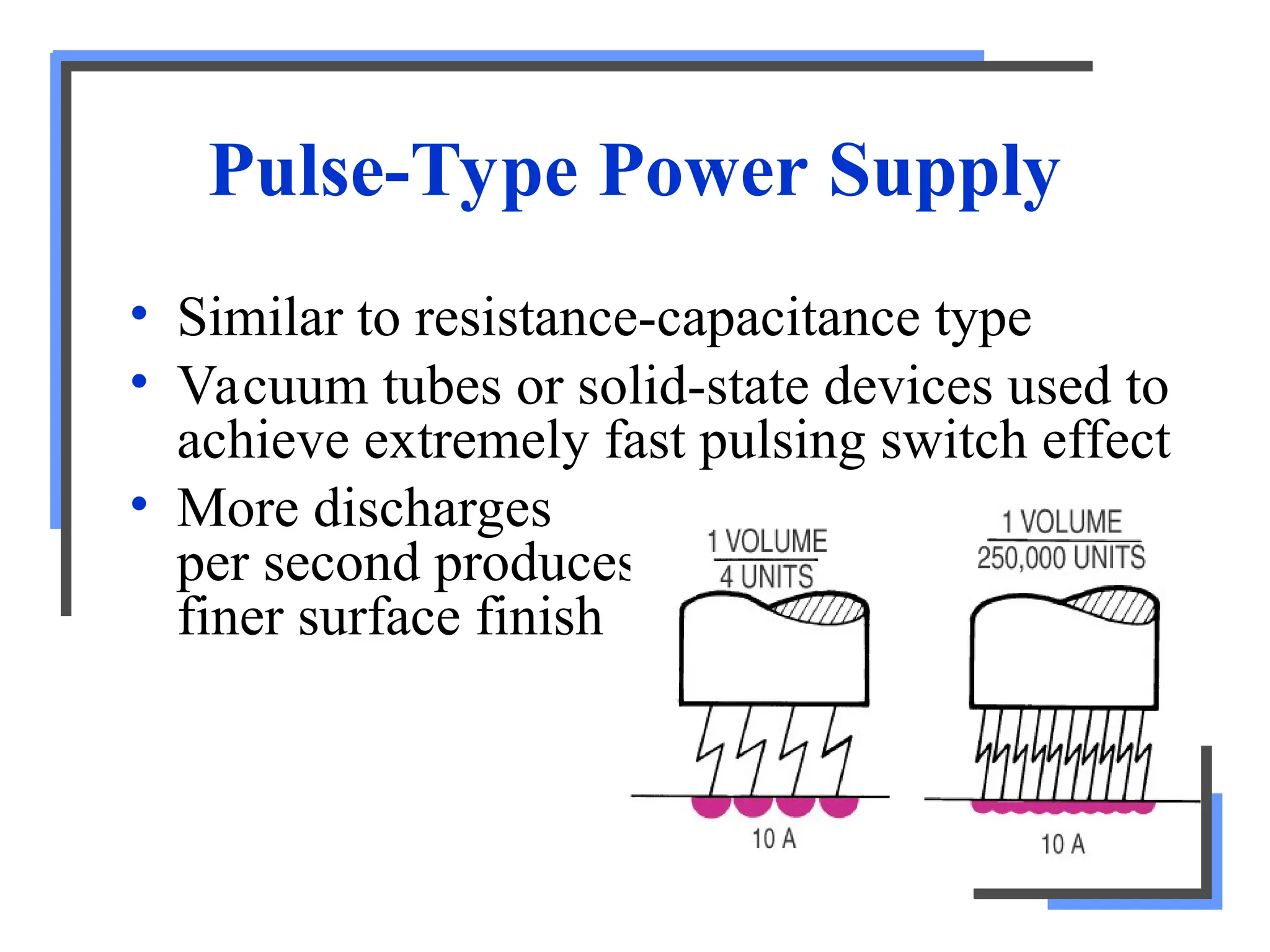
Pulse-Type Power Supply
•Similar to resistance-capacitance type
• Vacuum tubes or solid-state devices used to
achieve extremely fast pulsing switch effect
• More discharges
per second produces
finer surface finish
10.
Main Advantages of
Pulse-TypeCircuit
• Versatile and can be accurately controlled
for roughing and finishing cuts
• Better surface finish produced as less metal
removed per spark
– Many sparks per unit of time
• Less overcut around electrode (tool)
11.
The Electrode
• Formedto shape of cavity desired
• Characteristics of good electrode materials:
– Be good conductors of electricity and heat
– Be easily machined to shape at reasonable cost
– Produce efficient metal removal from work
– Resist deformation during erosion process
– Exhibit low electrode (tool) wear rates
12.
Electrode
• Common materials(not general-purpose)
– Graphite, cooper, copper graphite, copper tungsten,
brass, and steel
• Yellow brass used for pulse-type circuits
– Good machinability, electrical conductivity
• Copper used in resistance-capacitance circuits
with higher voltages
• Graphite
– Gaining acceptance, relatively inexpensive
– Tool wear rate less and high metal-removal rate almost
double of other materials
13.
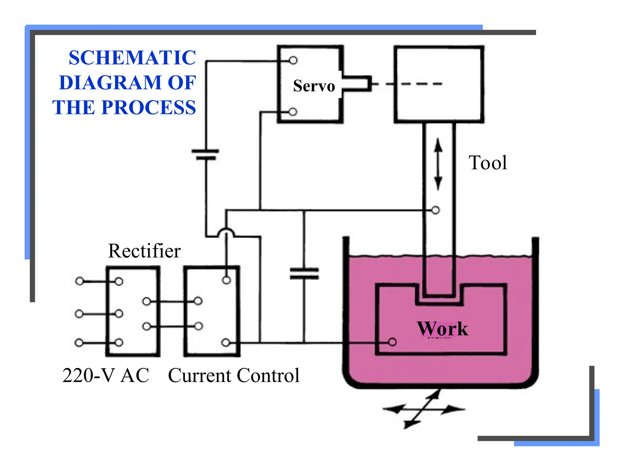
EDM Process
• Servomechanism
– Automatically maintains constant gap ~.0005
to .001 in. between electrode and work
– Advance tool into workpiece, senses and corrects
any shorted condition by rapidly retracting tool
(vertical movement)
– Feed control applied to table for horizontal moves
• EDM power supply
– Provides direct current electrical energy for
electrical discharges between tool and work
14.
Characteristics of
Pulse-Type Circuits
1.Low voltages
• Normally about 70 V, drops to 20 V after
spark initiated
2. Low capacitance
• About 50 mF or less
3. High frequencies
• Usually 20,000 to 30,000 Hz
4. Low-energy spark levels
15.
The Discharge Process
•Dielectric fluid changes into gas when
sufficient electrical energy applied
• Allows heavy discharge of current to flow
through ionized path and strike workpiece
• Heat between electrode and work surface
causes small pool of molten metal to form
on work surface
16.
• Current stopped(microseconds), molten
metal particles solidify and washed away
• Electrical discharges occur at rate of 20,000
to 30,000 Hz
– Each discharge removes minute amount of
metal
– Voltage constant so amount of metal removed
will be proportional to amount of charge
between electrode and work
• Current maintained but frequency increased,
results in smaller craters and better surface
17.
Main Functions of
DielectricFluid
1. Serves as insulator between tool and
workpiece until required voltage reached
2. Vaporizes (ionizes) to initiate spark
between electrode and workpiece
3. Confines spark path to narrow channel
4. Flushes away metal particles to prevent
shorting
5. Acts as coolant for both electrode and
workpiece
18.
Types of Dielectrics
•Must be able to ionize and deionize rapidly
and have low viscosity
– Allow them to be pumped through narrow
machining gap
• Most common have been various petroleum
products
– Light lubricating oils, transformer oils, silicon-
base oils and kerosene
• Selection of dielectric important since it
affects metal-removal rate and electrode
wear
19.
Methods of Circulating
Dielectrics
•Must be circulated under constant pressure
• Pressure used generally begins with 5 psi
and increased until optimum cutting
obtained
• Four methods to circulate dielectric fluid
– All must use fine filters in system to remove
metal particles so they are not recirculated
20.
Down Through theElectrode
Pressure
• Hole drilled through electrode and dielectric
fluid forced through electrode
and between it and work
Rapidly flushes away
metal particles
21.
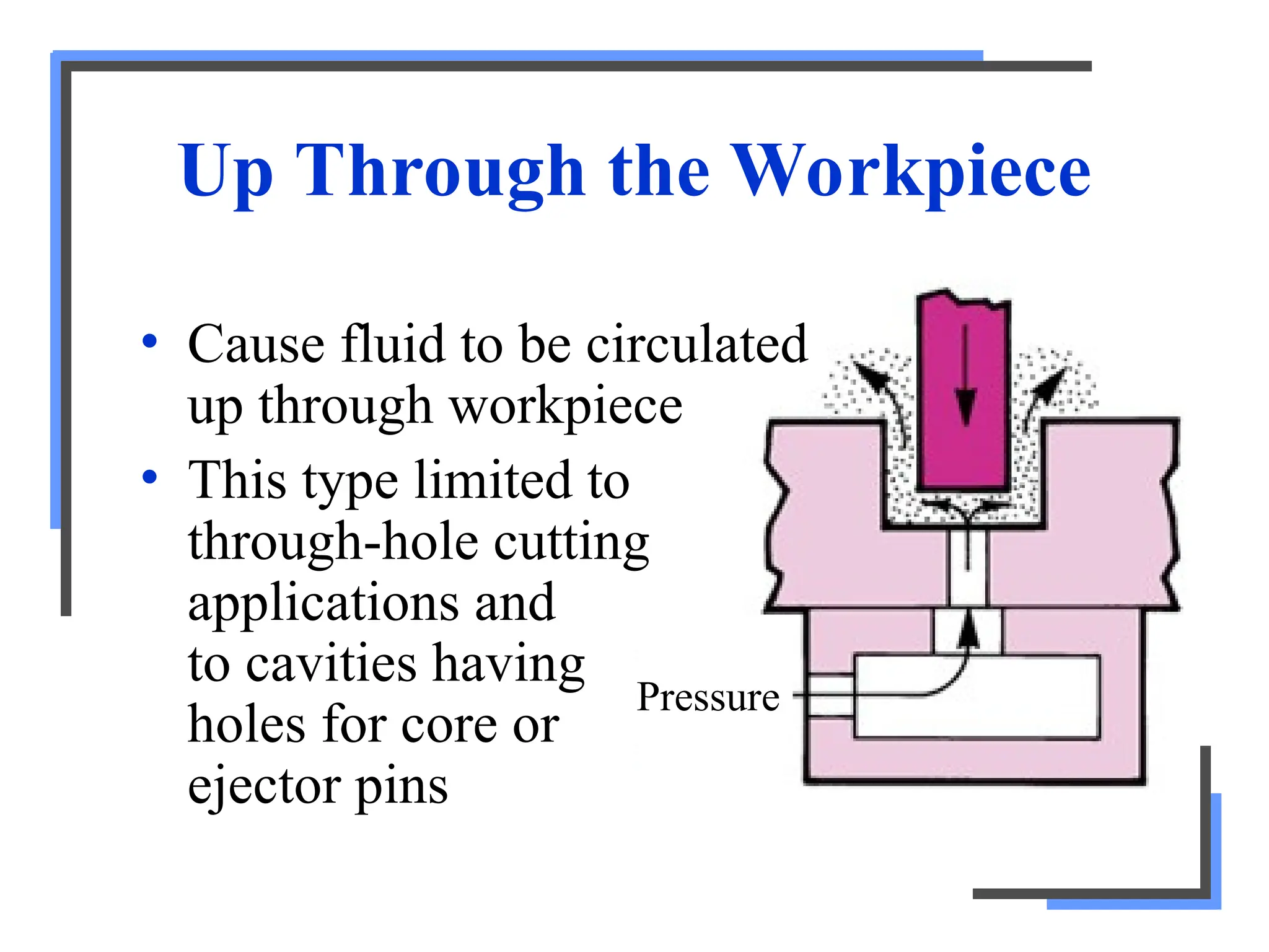
Up Through theWorkpiece
Pressure
• Cause fluid to be circulated
up through workpiece
• This type limited to
through-hole cutting
applications and
to cavities having
holes for core or
ejector pins
22.
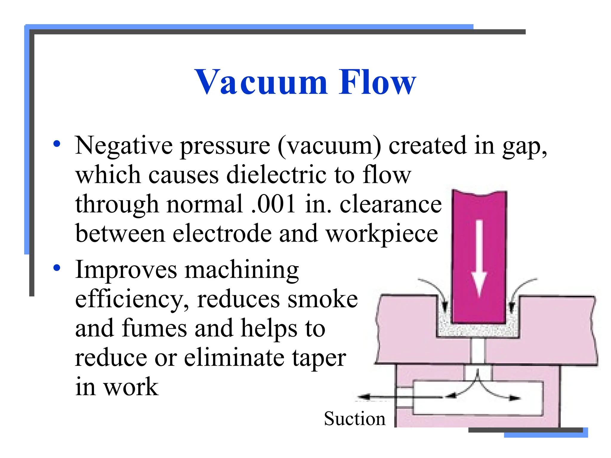
Vacuum Flow
Suction
• Negativepressure (vacuum) created in gap,
which causes dielectric to flow
through normal .001 in. clearance
between electrode and workpiece
• Improves machining
efficiency, reduces smoke
and fumes and helps to
reduce or eliminate taper
in work
23.
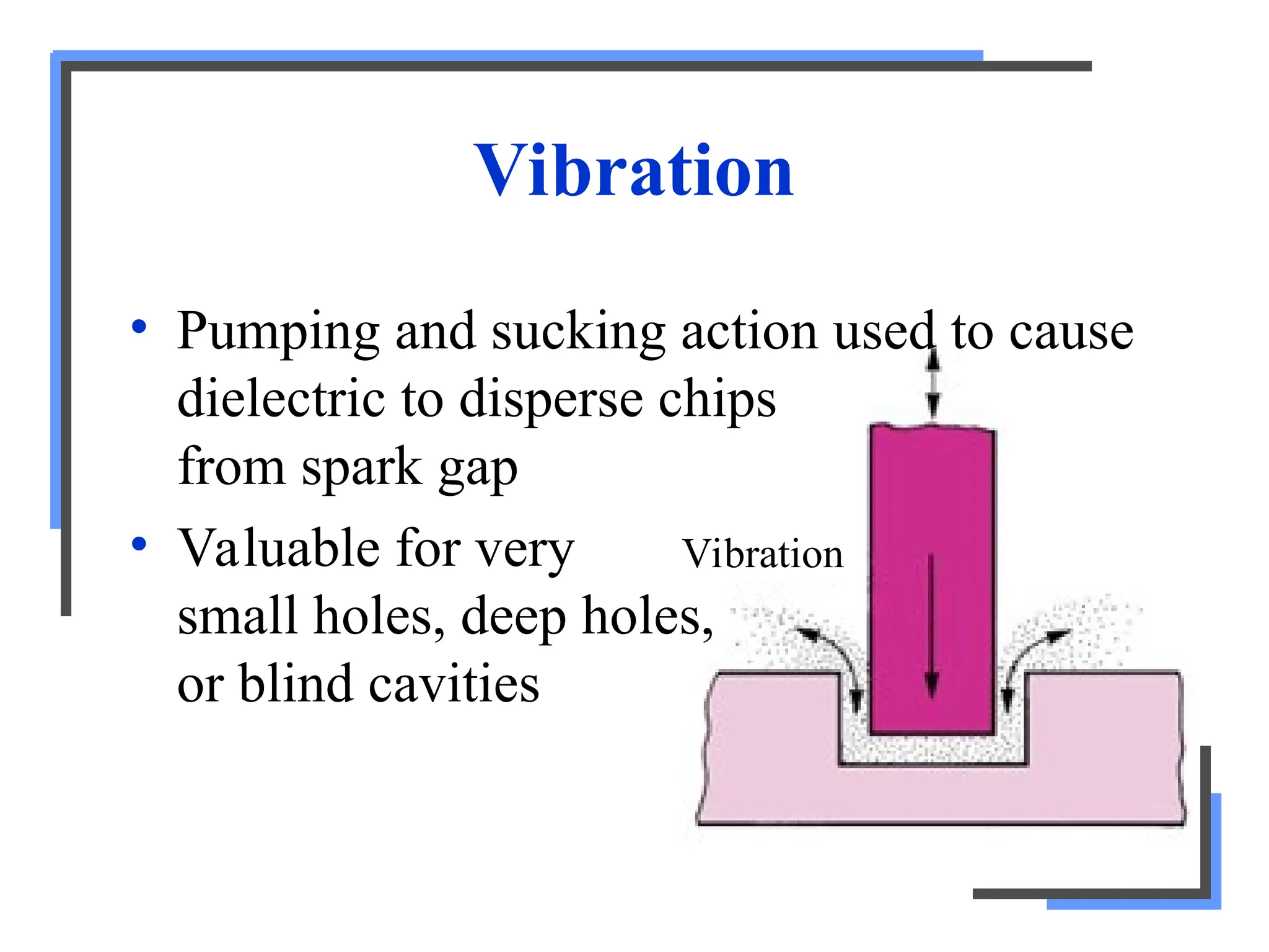
Vibration
Vibration
• Pumping andsucking action used to cause
dielectric to disperse chips
from spark gap
• Valuable for very
small holes, deep holes,
or blind cavities
24.
Metal-Removal Rates
• Ratedependent on following factors:
– Amount of current in each discharge
– Frequency of discharge
– Electrode material
– Workpiece material
– Dielectric flushing conditions
• Normal metal-removal rate ~1 in3
work
material per hour for every 20 A of current
25.
Electrode (Tool) Wear
•During discharge process, tool subject to
wear or erosion
• Difficult to hold close tolerances as tool
gradually loses its shape during machining
operation
• Average wear ratio of workpiece to
electrode is 3:1 for metallic tools
– Graphite electrodes wear ratio 10:1
26.
Reverse-Polarity Machining
• Newdevelopment that promises to be major
breakthrough in reducing electrode wear
• Molten metal from workpiece deposited on
graphite electrode about as fast as electrode
worn away
• Operates best on low spark-discharge
frequencies and high amperage
• Improves metal-removal rates and reduces
electrode wear
27.
Overcut
• Amount thecavity in the workpiece is cut
larger than the size of electrode used in
machining process
• Distance between surface of work and
surface of electrode (overcut) is equal to
length of sparks discharged
– Constant over all areas of electrode
• Amount ranges from .0002 to .007 in. and
dependent on amount of gap voltage
28.
95-28
Overcut
• Amount variedto suit metal-removal rate
and surface finish required
– Determines size of chip removal
• Size of chip removed important factor in
setting amount of overcut because:
1. Chip in space between electrode and work
serve as conductors for electrical discharges
2. Large chips produced with higher amperages
require larger gap to enable them to be flushed
out effectively
29.
Surface Finish
• Lowmetal-removal rates, surface finishes of 2 to
4 µin. possible
• High metal-removal rates, finishes of
1000 µin. produced
• Fast metal removal (roughing cuts)
– High amperage, low frequency, high capacitance and
minimum gap voltage required
• Slow metal removal (finish cut)
– Low amperage, high frequency, low capacitance and
highest gap voltage required
30.
Advantages of EDM
•Any material that is electrically conductive
can be cut, regardless of its hardness
• Work can be machined in hardened state,
thereby overcoming deformation caused by
hardening process
• Broken taps or drills can readily be removed
from workpieces
31.
• Does notcreate stresses in work material,
since tool never comes into contact with work
• Process is burr-free
• Thin, fragile sections easily machined without
deforming
• Process is automatic – servo mechanism
advances electrode into work as metal
removed
• One person can operate several EDM
machines at one time
32.
• Intricate shapes,impossible to produce by
conventional means, are cut out of a solid
with relative ease
• Better dies and molds can be produced at
lower cost
• A die punch can be used as electrode to
reproduce its shape in matching die plate,
complete with necessary clearance
33.
Limitations of EDM
•Metal-removal rates are low
• Material to be machined must be electrically
conductive
• Cavities produced are slightly tapered but
can be controlled for most applications to as
little as .0001 in. in every .250 in.
34.
• Rapid electrodewear can be come costly in
some types of EDM equipment
• Electrodes smaller than .003 in. in diameter
are impractical
• Work surface is damaged to depth of
.0002 in. but is easily removed
• Slight case hardening occurs
– However, may be classed as advantage in some
instances
35.
Wire-Cut EDM Machine
•Uses thin brass or copper wire as electrode
• Makes possible cutting most shapes and
contours from flat plate materials
– Complex shapes: tapers, involutes, parabolas,
and ellipses
• Process commonly used for:
– Machining tungsten carbide, polycrystalline
diamond, polycrystalline cubic boron nitride,
pure molybdenum, difficult-to-machine material
36.
The Process
• UsesCNC to move workpiece along X and Y
axes in horizontal plane toward vertically
moving wire electrode
• Electrode does not contact workpiece but
operates in stream of dielectric fluid
– Directed to spark area between work and
electrode
– When in operation, dielectric fluid in spark area
breaks down, forming gas that permits spark to
jump between workpiece and electrode
– Eroded material caused by spark washed away
37.
Operating Systems
• Fourmain operating systems of wire-cut
electrical discharge machines
– Servo mechanism
– Dielectric fluid
– Electrode
– Machine control unit
38.
Servo Mechanism
• Controlscutting current levels, feed rate of
drive motors, and traveling speed of wire
• Automatically maintains constant gap of .001
to .002 in. between wire and workpiece
– Important there be no physical contact
• Advances workpiece into wire, senses work-
wire spacing, and slows or speeds up drive
motors to maintain proper arc gap
39.
Dielectric Fluid
• Usuallydeionized water
• Serves several functions:
1. Helps initiate spark between wire and work
2. Serves as insulator between wire and work
3. Flushes away particles of disintegrated wire
and work from gap to prevent shorting
4. Acts as coolant for both wire and workpiece
40.
Electrode
• Spool ofbrass, copper, tungsten,
molybdenum, or zinc wire ranging from .002
to .012 in. in diameter (2 to 100 lb)
– Continuously travels from supply spool to
takeup spool so new wire always in spark area
• Both electrode wear and material-removal
rate from workpiece depend on:
– Material's electrical and thermal conductivity, its
melting point and duration and intensity of
electrical pulses
41.
Characteristics of
Electrode Materials
1.Be good conductor of electricity
2. Have high melting point
3. Have high tensile strength
4. Have good thermal conductivity
5. Produce efficient metal removal from
workpiece
42.
Machine Control Unit
•Separated into three individual operator
panels
– Control panel for setting cutting conditions
(servo mechanism)
– Control panel for machine setup and data
required to produce part (numerical control)
– Control panel for manual data input (MDI) and
cathode ray tube display