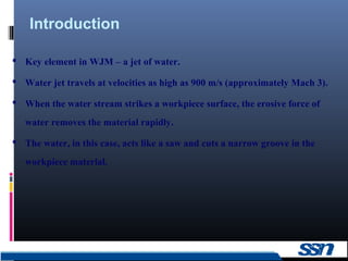
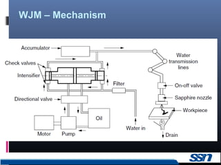
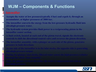
Water jet machining uses a high-pressure jet of water to cut materials. Key components include an intensifier that increases water pressure to 3800 bar, an accumulator that maintains uniform pressure, and a sapphire nozzle that forms the jet. It can cut a variety of materials with few limitations and without heat or tool wear. Advantages are flexibility, accuracy, minimal kerf and burrs, and no heat affected zones.


![WJM – Components & Functions
8
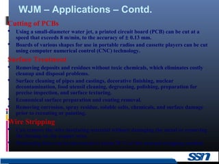
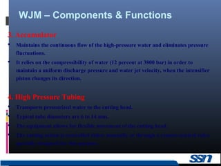
5. Jet Cutting Nozzle
Nozzle provides a coherent water jet stream for optimum cutting of low-density,
soft material that is considered unmachinable by conventional methods.
Nozzles are normally made from synthetic sapphire.
About 200 h of operation are expected from a nozzle, which becomes damaged by
particles of dirt and the accumulation of mineral deposits on the orifice due to
erosive water hardness.
A longer nozzle life can be obtained through multistage filtration, which removes
undesired solids of size greater than 0.45 μm.
The compact design of the water jet cutting head promotes integration with
motion control systems ranging from two-axis (XY) tables to sophisticated multiaxis
robotic installations.
6. Catcher
Acts as a reservoir for collecting the machining debris entrained in the water jet.
Moreover, it reduces the noise levels [105 decibels (dB)] associated with the
reduction in the velocity of the water jet from Mach 3 to subsonic levels.](https://image.slidesharecdn.com/wjm-170901062126/85/Water-jet-machining-8-320.jpg)