Downloaded 615 times
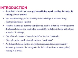
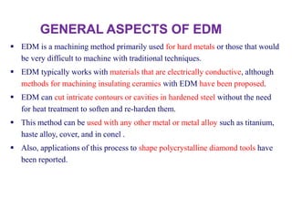
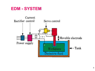
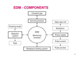
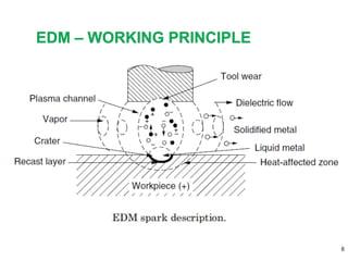
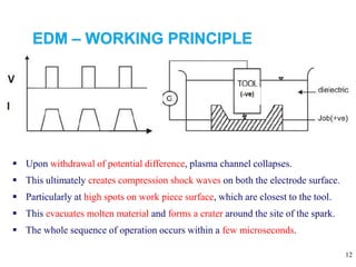
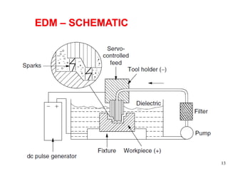
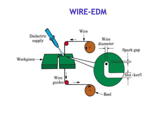


Electrical Discharge Machining (EDM) is a manufacturing process that uses electrical sparks to remove material from a conductive workpiece. In the EDM process, a tool electrode is moved close to the workpiece and an electric spark is generated via a dielectric fluid between them, vaporizing a small amount of material. This process is repeated many times to gradually shape the workpiece. EDM can machine very hard materials and complex shapes without causing mechanical stress to the workpiece. Common applications include drilling micro holes, cutting intricate profiles, and machining hardened steel dies and molds.


