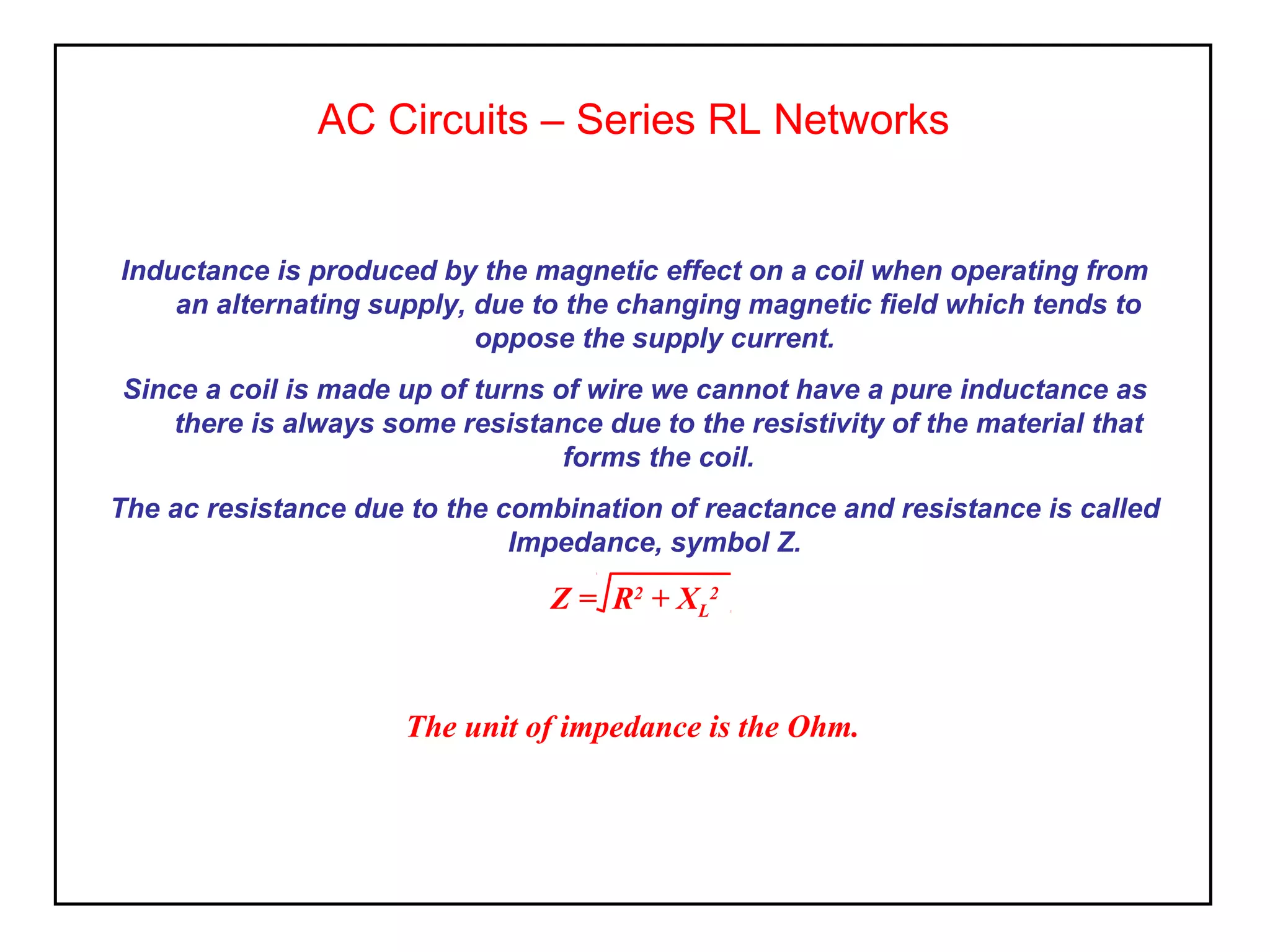
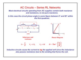
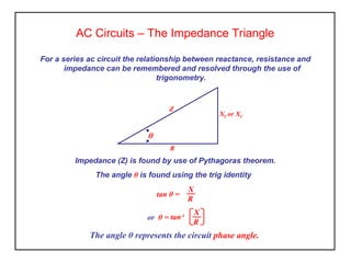
AC Circuits – Series RL Networks
The unit of impedance is the Ohm.
Inductance is produced by the magnetic effect on a coil when operating from
an alternating supply, due to the changing magnetic field which tends to
oppose the supply current.
Since a coil is made up of turns of wire we cannot have a pure inductance as
there is always some resistance due to the resistivity of the material that
forms the coil.
The ac resistance due to the combination of reactance and resistance is called
Impedance, symbol Z.
Z = R2
+ XL
2
Most electrical circuits operating from AC supplies contain both reactance
and resistance, ie not pure reactance.
In this case the circuit phase angle is some figure between 0° and 90° within
the first quadrant.
Inductive circuits cause the current to lag the applied emf since the inductance
also posses resistance due to the winding that forms the coil.
Inductance and
resistance
L R
I
V
(AC)
VR
VL
Phasor Diagram
I
VR
VL
V
Ø
I = VL = I XL VR = I R
V
Z
θ = Tan-1
R
XL
AC Circuits – Series RL Networks
Activity
Inductive
1. A coil having an inductance of 200mH and a resistance of 80Ω is connected
to a 230 volt 50Hz. supply. Determine the current flowing in the circuit and
the phase angle between current and applied emf.
2. Repeat (1) for a frequency of 100Hz. and comment on your results.
3. In each case draw the phasor diagram to scale and compare with calculated
results.
AC Circuits – Series RL Networks
AC Circuits – The Impedance Triangle
The angle θ represents the circuit phase angle.
For a series ac circuit the relationship between reactance, resistance and
impedance can be remembered and resolved through the use of
trigonometry.
Z
R
XL or XC
θ
Impedance (Z) is found by use of Pythagoras theorem.
The angle θ is found using the trig identity
R
X
tan θ =
or θ = tan-1
R
X
Impedance – Summary
• The effective resistance of an ac circuit is called ‘Impedance (Z)’ and is
formed through the combination of resistance and reactance.
• Impedance has units of Ohms.
• Phasor diagrams represent the voltages operating in the circuit at their
relative angles.
• The impedance triangle demonstrates the relationship of the resistive
quantities and their respective angles.

Elect principles 2 ac circuits (rl)

  • 1.
    AC Circuits –Series RL Networks The unit of impedance is the Ohm. Inductance is produced by the magnetic effect on a coil when operating from an alternating supply, due to the changing magnetic field which tends to oppose the supply current. Since a coil is made up of turns of wire we cannot have a pure inductance as there is always some resistance due to the resistivity of the material that forms the coil. The ac resistance due to the combination of reactance and resistance is called Impedance, symbol Z. Z = R2 + XL 2
  • 2.
    Most electrical circuitsoperating from AC supplies contain both reactance and resistance, ie not pure reactance. In this case the circuit phase angle is some figure between 0° and 90° within the first quadrant. Inductive circuits cause the current to lag the applied emf since the inductance also posses resistance due to the winding that forms the coil. Inductance and resistance L R I V (AC) VR VL Phasor Diagram I VR VL V Ø I = VL = I XL VR = I R V Z θ = Tan-1 R XL AC Circuits – Series RL Networks
  • 3.
    Activity Inductive 1. A coilhaving an inductance of 200mH and a resistance of 80Ω is connected to a 230 volt 50Hz. supply. Determine the current flowing in the circuit and the phase angle between current and applied emf. 2. Repeat (1) for a frequency of 100Hz. and comment on your results. 3. In each case draw the phasor diagram to scale and compare with calculated results. AC Circuits – Series RL Networks
  • 4.
    AC Circuits –The Impedance Triangle The angle θ represents the circuit phase angle. For a series ac circuit the relationship between reactance, resistance and impedance can be remembered and resolved through the use of trigonometry. Z R XL or XC θ Impedance (Z) is found by use of Pythagoras theorem. The angle θ is found using the trig identity R X tan θ = or θ = tan-1 R X
  • 5.
    Impedance – Summary •The effective resistance of an ac circuit is called ‘Impedance (Z)’ and is formed through the combination of resistance and reactance. • Impedance has units of Ohms. • Phasor diagrams represent the voltages operating in the circuit at their relative angles. • The impedance triangle demonstrates the relationship of the resistive quantities and their respective angles.
  • 6.
    Impedance – Summary •The effective resistance of an ac circuit is called ‘Impedance (Z)’ and is formed through the combination of resistance and reactance. • Impedance has units of Ohms. • Phasor diagrams represent the voltages operating in the circuit at their relative angles. • The impedance triangle demonstrates the relationship of the resistive quantities and their respective angles.