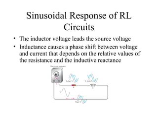
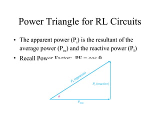
Chapter 12
RL Circuits
Objectives
• Describe the relationship between current
and voltage in an RL circuit
• Determine impedance and phase angle in a
series RL circuit
• Analyze a series RL circuit
• Determine impedance and phase angle in a
parallel RL circuit
Objectives
• Analyze a parallel RL circuit
• Analyze series-parallel RL circuits
• Determine power in RL circuits
Sinusoidal Response of RL
Circuits
• The inductor voltage leads the source voltage
• Inductance causes a phase shift between voltage
and current that depends on the relative values of
the resistance and the inductive reactance
Impedance and Phase Angle of
Series RL Circuits
• Impedance of any RL circuit is the total opposition
to sinusoidal current and its unit is the ohm
• The phase angle is the phase difference between
the total current and the source voltage
• The impedance of a series RL circuit is
determined by the resistance (R) and the inductive
reactance (XL)
The Impedance Triangle
• In ac analysis, both R and XL are treated a phasor
quantities, with XL appearing at a +90° angle with respect
to R
∀ θ is the phase angle between applied voltage and current
The Impedance Triangle
• The impedance magnitude of the series RL
circuit in terms of resistance and reactance:
Z = √R2
+ X2
L
– The magnitude of the impedance (Z) is
expressed in ohms
• The phase angle is:
θ = tan-1
(XL/R)
Ohm’s Law
• Application of Ohm’s Law to series RL
circuits involves the use of the phasor
quantities Z, V, and I
V = IZ
I = V/Z
Z = V/I
Relationships of the Current and
Voltages in a Series RL Circuit
• Resistor voltage is in
phase with the current
• Inductor voltage leads
the current by 90°
• There is a phase
difference of 90°
between the resistor
voltage, VR, and the
inductor voltage, VL
Kirchhoff’s Voltage Law
• From KVL, the sum of the voltage drops must
equal the applied voltage
• The magnitude of the source voltage is:
Vs = √V2
R + V2
L
• The phase angle between resistor voltage and
source voltage is:
θ = tan-1
(VL/VR)
Variation of Impedance and
Phase Angle with Frequency
• Inductive reactance varies directly with frequency
• Z is directly dependent on frequency
• Phase angle θ also varies directly with frequency
Impedance and Phase Angle of
Parallel RL Circuits
• The magnitude of the total impedance of a
two-component parallel RL circuit is:
Z = RXL/ √R2
+ X2
L
• The phase angle between the applied
voltage and the total current is:
θ = tan-1
(R/XL)
Conductance (G), Susceptance (B),
and Admittance (Y)
• Conductance is: G = 1/R
• Inductive Susceptance is: BL = 1/XL
• Admittance is: Y = 1/Z
• Total admittance is the phasor sum of conductance
and the inductive susceptance:
Y = √G2
+ B2
L
The unit for G, BL an Y is siemens (S)
Analysis of Parallel RL Circuits
• The total current, Itot , divides at the junction into
the two branch currents, IR and IL
• Vs, VR , and VL are all in phase and of the same
magnitude
Kirchhoff’s Current Law
• The current through the inductor lags the voltage
and the resistor current by 90°
• By Kirchhoff’s Current Law, the total current is
the phasor sum of the two branch currents:
Itot = √I2
R + I2
L
• Phase angle: θ = tan-1
(IL/IR)
Series Parallel RL Circuits
• A first approach to analyzing circuits with
combinations of both series and parallel R
and L elements is to:
– Find the series equivalent resistance (R(eq)) and
inductive reactance (XL(eq)) for the parallel
portion of the circuit
– Add the resistances to get the total resistance
and add the reactances to get the total reactance
– Determine the total impedance
Series Parallel RL Circuits
• A second approach to analyzing circuits
with combinations of both series and
parallel R and L elements is to:
– Calculate the magnitudes of inductive reactance
(XL)
– Determine the impedance of each branch
– Calculate each branch current in polar form
– Use Ohm’s law to get element voltages
Power in RL Circuits
• When there is both resistance and inductance,
some of the energy is alternately stored and
returned by the inductance and some is dissipated
by the resistance
• The amount of energy converted to heat is
determined by the relative values of the resistance
and the inductive reactance
• The Power in the inductor is reactive power:
Pr = I2
XL
Power Triangle for RL Circuits
• The apparent power (Pa) is the resultant of the
average power (Ptrue) and the reactive power (PR)
• Recall Power Factor: PF = cos θ
Significance of the Power Factor
• Many practical loads have inductance as a
result of their particular function, and it is
essential for their proper operation
• Examples are: transformers, electric motors
and speakers
• A higher power factor is an advantage in
delivering power more efficiently to a load
Power Factor Correction
• Power factor of an inductive load can be
increased by the addition of a capacitor in
parallel
– The capacitor compensates for the the phase lag
of the total current by creating a capacitive
component of current that is 180° out of phase
with the inductive component
– This has a canceling effect and reduces the
phase angle (and power factor) as well as the
total current, as illustrated on next slide
Power Factor Correction
RL Circuit as a Low-Pass Filter
• An inductor acts as a short to dc
• As the frequency is increased, so does the
inductive reactance
– As inductive reactance increases, the output
voltage across the resistor decreases
– A series RL circuit, where output is taken
across the resistor, finds application as a low-
pass filter
RL Circuit as a High-Pass Filter
• For the case when output voltage is
measured across the inductor
– At dc, the inductor acts a short, so the output
voltage is zero
– As frequency increases, so does inductive
reactance, resulting in more voltage being
dropped across the inductor
– The result is a high-pass filter
Summary
• When a sinusoidal voltage is applied to an RL
circuit, the current and all the voltage drops are
also sine waves
• Total current in an RL circuit always lags the
source voltage
• The resistor voltage is always in phase with the
current
• In an ideal inductor, the voltage always leads the
current by 90°
Summary
• In an RL circuit, the impedance is determined by
both the resistance and the inductive reactance
combined
• Impedance is expressed in units of ohms
• The impedance of an RL circuit varies directly
with frequency
• The phase angle (θ) if a series RL circuit varies
directly with frequency
Summary
• You can determine the impedance of a circuit by
measuring the source voltage and the total current
and then applying Ohm’s law
• In an RL circuit, part of the power is resistive and
part reactive
• The phasor combination of resistive power and
reactive power is called apparent power
• The power factor indicates how much of the
apparent power is true power
Summary
• A power factor of 1 indicates a purely resistive
circuit, and a power factor of 0 indicates a purely
reactive circuit
• In an RL lag network, the output voltage lags the
input voltage in phase
• In an RL lead network, the output voltage leads
the input voltage in phase
• A filter passes certain frequencies and rejects
others

Ch12 ln

  • 1.
  • 2.
    Objectives • Describe therelationship between current and voltage in an RL circuit • Determine impedance and phase angle in a series RL circuit • Analyze a series RL circuit • Determine impedance and phase angle in a parallel RL circuit
  • 3.
    Objectives • Analyze aparallel RL circuit • Analyze series-parallel RL circuits • Determine power in RL circuits
  • 4.
    Sinusoidal Response ofRL Circuits • The inductor voltage leads the source voltage • Inductance causes a phase shift between voltage and current that depends on the relative values of the resistance and the inductive reactance
  • 5.
    Impedance and PhaseAngle of Series RL Circuits • Impedance of any RL circuit is the total opposition to sinusoidal current and its unit is the ohm • The phase angle is the phase difference between the total current and the source voltage • The impedance of a series RL circuit is determined by the resistance (R) and the inductive reactance (XL)
  • 6.
    The Impedance Triangle •In ac analysis, both R and XL are treated a phasor quantities, with XL appearing at a +90° angle with respect to R ∀ θ is the phase angle between applied voltage and current
  • 7.
    The Impedance Triangle •The impedance magnitude of the series RL circuit in terms of resistance and reactance: Z = √R2 + X2 L – The magnitude of the impedance (Z) is expressed in ohms • The phase angle is: θ = tan-1 (XL/R)
  • 8.
    Ohm’s Law • Applicationof Ohm’s Law to series RL circuits involves the use of the phasor quantities Z, V, and I V = IZ I = V/Z Z = V/I
  • 9.
    Relationships of theCurrent and Voltages in a Series RL Circuit • Resistor voltage is in phase with the current • Inductor voltage leads the current by 90° • There is a phase difference of 90° between the resistor voltage, VR, and the inductor voltage, VL
  • 10.
    Kirchhoff’s Voltage Law •From KVL, the sum of the voltage drops must equal the applied voltage • The magnitude of the source voltage is: Vs = √V2 R + V2 L • The phase angle between resistor voltage and source voltage is: θ = tan-1 (VL/VR)
  • 11.
    Variation of Impedanceand Phase Angle with Frequency • Inductive reactance varies directly with frequency • Z is directly dependent on frequency • Phase angle θ also varies directly with frequency
  • 12.
    Impedance and PhaseAngle of Parallel RL Circuits • The magnitude of the total impedance of a two-component parallel RL circuit is: Z = RXL/ √R2 + X2 L • The phase angle between the applied voltage and the total current is: θ = tan-1 (R/XL)
  • 13.
    Conductance (G), Susceptance(B), and Admittance (Y) • Conductance is: G = 1/R • Inductive Susceptance is: BL = 1/XL • Admittance is: Y = 1/Z • Total admittance is the phasor sum of conductance and the inductive susceptance: Y = √G2 + B2 L The unit for G, BL an Y is siemens (S)
  • 14.
    Analysis of ParallelRL Circuits • The total current, Itot , divides at the junction into the two branch currents, IR and IL • Vs, VR , and VL are all in phase and of the same magnitude
  • 15.
    Kirchhoff’s Current Law •The current through the inductor lags the voltage and the resistor current by 90° • By Kirchhoff’s Current Law, the total current is the phasor sum of the two branch currents: Itot = √I2 R + I2 L • Phase angle: θ = tan-1 (IL/IR)
  • 16.
    Series Parallel RLCircuits • A first approach to analyzing circuits with combinations of both series and parallel R and L elements is to: – Find the series equivalent resistance (R(eq)) and inductive reactance (XL(eq)) for the parallel portion of the circuit – Add the resistances to get the total resistance and add the reactances to get the total reactance – Determine the total impedance
  • 17.
    Series Parallel RLCircuits • A second approach to analyzing circuits with combinations of both series and parallel R and L elements is to: – Calculate the magnitudes of inductive reactance (XL) – Determine the impedance of each branch – Calculate each branch current in polar form – Use Ohm’s law to get element voltages
  • 18.
    Power in RLCircuits • When there is both resistance and inductance, some of the energy is alternately stored and returned by the inductance and some is dissipated by the resistance • The amount of energy converted to heat is determined by the relative values of the resistance and the inductive reactance • The Power in the inductor is reactive power: Pr = I2 XL
  • 19.
    Power Triangle forRL Circuits • The apparent power (Pa) is the resultant of the average power (Ptrue) and the reactive power (PR) • Recall Power Factor: PF = cos θ
  • 20.
    Significance of thePower Factor • Many practical loads have inductance as a result of their particular function, and it is essential for their proper operation • Examples are: transformers, electric motors and speakers • A higher power factor is an advantage in delivering power more efficiently to a load
  • 21.
    Power Factor Correction •Power factor of an inductive load can be increased by the addition of a capacitor in parallel – The capacitor compensates for the the phase lag of the total current by creating a capacitive component of current that is 180° out of phase with the inductive component – This has a canceling effect and reduces the phase angle (and power factor) as well as the total current, as illustrated on next slide
  • 22.
  • 23.
    RL Circuit asa Low-Pass Filter • An inductor acts as a short to dc • As the frequency is increased, so does the inductive reactance – As inductive reactance increases, the output voltage across the resistor decreases – A series RL circuit, where output is taken across the resistor, finds application as a low- pass filter
  • 24.
    RL Circuit asa High-Pass Filter • For the case when output voltage is measured across the inductor – At dc, the inductor acts a short, so the output voltage is zero – As frequency increases, so does inductive reactance, resulting in more voltage being dropped across the inductor – The result is a high-pass filter
  • 25.
    Summary • When asinusoidal voltage is applied to an RL circuit, the current and all the voltage drops are also sine waves • Total current in an RL circuit always lags the source voltage • The resistor voltage is always in phase with the current • In an ideal inductor, the voltage always leads the current by 90°
  • 26.
    Summary • In anRL circuit, the impedance is determined by both the resistance and the inductive reactance combined • Impedance is expressed in units of ohms • The impedance of an RL circuit varies directly with frequency • The phase angle (θ) if a series RL circuit varies directly with frequency
  • 27.
    Summary • You candetermine the impedance of a circuit by measuring the source voltage and the total current and then applying Ohm’s law • In an RL circuit, part of the power is resistive and part reactive • The phasor combination of resistive power and reactive power is called apparent power • The power factor indicates how much of the apparent power is true power
  • 28.
    Summary • A powerfactor of 1 indicates a purely resistive circuit, and a power factor of 0 indicates a purely reactive circuit • In an RL lag network, the output voltage lags the input voltage in phase • In an RL lead network, the output voltage leads the input voltage in phase • A filter passes certain frequencies and rejects others