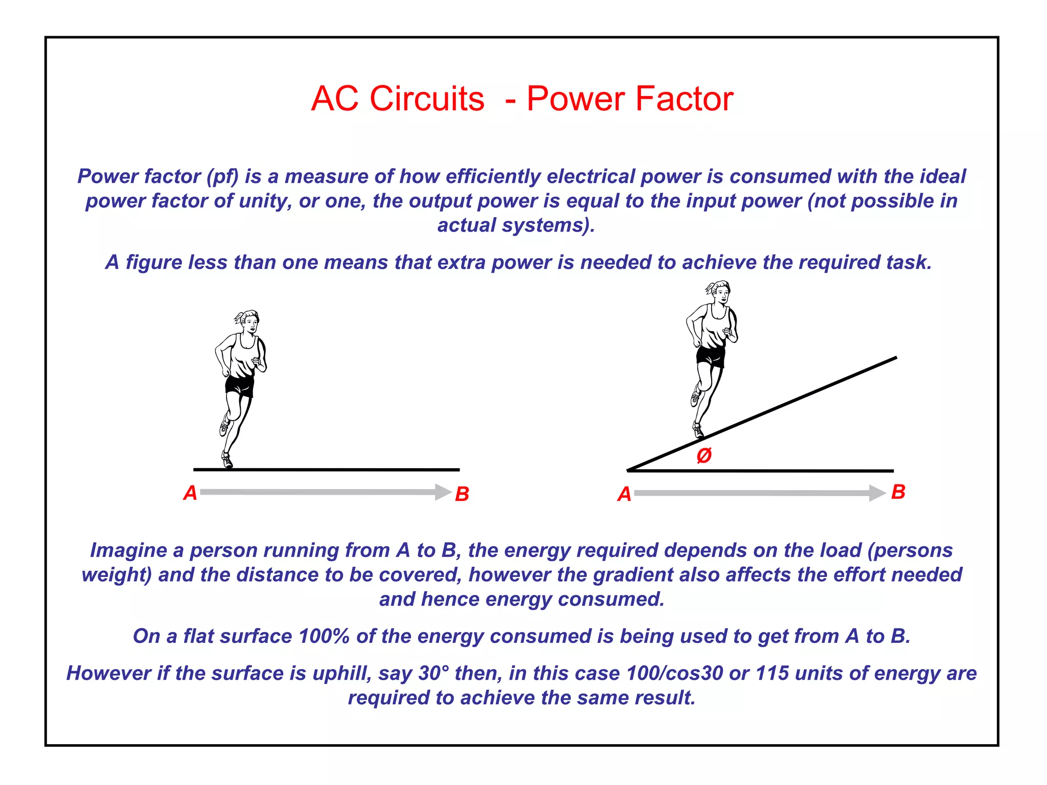
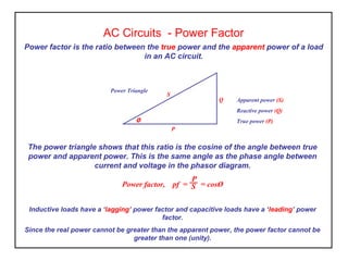
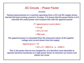
AC Circuits - Power Factor
Power factor (pf) is a measure of how efficiently electrical power is consumed with the ideal
power factor of unity, or one, the output power is equal to the input power (not possible in
actual systems).
A figure less than one means that extra power is needed to achieve the required task.
A B A
Ø
B
Imagine a person running from A to B, the energy required depends on the load (persons
weight) and the distance to be covered, however the gradient also affects the effort needed
and hence energy consumed.
On a flat surface 100% of the energy consumed is being used to get from A to B.
However if the surface is uphill, say 30° then, in this case 100/cos30 or 115 units of energy are
required to achieve the same result.
AC Circuits - Power Factor
Power factor is the ratio between the true power and the apparent power of a load
in an AC circuit.
The power triangle shows that this ratio is the cosine of the angle between true
power and apparent power. This is the same angle as the phase angle between
current and voltage in the phasor diagram.
Power factor, pf = = cosØ
Inductive loads have a ‘lagging’ power factor and capacitive loads have a ‘leading’ power
factor.
Since the real power cannot be greater than the apparent power, the power factor cannot be
greater than one (unity).
P
S
P
S
Q
Ø
Apparent power (S)
Reactive power (Q)
True power (P)
Power Triangle
AC Circuits - Power Factor
Example
Taking measurements on a machine operating from a 415 volt AC supply shows
that the full load running current is 12 amps. It is known that the power factor is 0.8
calculate the useful power and compare this with the apparent power
P = apparent power x power factor
= VI x pf
= 415 x 12 x 0.8
= 3984 watts
The apparent power is calculated from the measured values of the applied
voltage and current drawn from the supply.
Apparent power = VI
= 415 x 12 = 4980 (VA) or 4.98kVA
This is the power that we are charged for, it is therefore most desirable to
operate electrical machinery at a high power factor to minimise our losses and
reduce our costs.
Activity
1. Determine the power factor of a motor delivering 5kW when operating from a 415 volt AC
supply if the load current is 16 amps.
2. We wish reduce the running current of the above machine to 13 amps. What power factor
do we need to achieve this figure.
3. In each of the above situations determine, a) the power taken from the supply
(chargeable) and b) the efficiency.
4. Determine a) the power factor and b) the power dissipated for the circuit shown below;
AC Circuits - Power Factor
XL R=10Ω
I=10A
V
200V
50Hz
Power Factor – What did we learn
• Power factor is the ratio of true power to apparent power, cos(phase angle),
• Inductive loads have a ‘lagging’ power factor,
• Capacitive loads have a ‘leading’ power factor,
• Equipment operating at low power factors are expensive to run and waste
energy.
• It is desirable to operate equipment at a high power factor to reduce running
costs and energy used,
• Power factor is a figure between 0 and 1 (unity).

Elect principles 2 power factor

  • 1.
    AC Circuits -Power Factor Power factor (pf) is a measure of how efficiently electrical power is consumed with the ideal power factor of unity, or one, the output power is equal to the input power (not possible in actual systems). A figure less than one means that extra power is needed to achieve the required task. A B A Ø B Imagine a person running from A to B, the energy required depends on the load (persons weight) and the distance to be covered, however the gradient also affects the effort needed and hence energy consumed. On a flat surface 100% of the energy consumed is being used to get from A to B. However if the surface is uphill, say 30° then, in this case 100/cos30 or 115 units of energy are required to achieve the same result.
  • 2.
    AC Circuits -Power Factor Power factor is the ratio between the true power and the apparent power of a load in an AC circuit. The power triangle shows that this ratio is the cosine of the angle between true power and apparent power. This is the same angle as the phase angle between current and voltage in the phasor diagram. Power factor, pf = = cosØ Inductive loads have a ‘lagging’ power factor and capacitive loads have a ‘leading’ power factor. Since the real power cannot be greater than the apparent power, the power factor cannot be greater than one (unity). P S P S Q Ø Apparent power (S) Reactive power (Q) True power (P) Power Triangle
  • 3.
    AC Circuits -Power Factor Example Taking measurements on a machine operating from a 415 volt AC supply shows that the full load running current is 12 amps. It is known that the power factor is 0.8 calculate the useful power and compare this with the apparent power P = apparent power x power factor = VI x pf = 415 x 12 x 0.8 = 3984 watts The apparent power is calculated from the measured values of the applied voltage and current drawn from the supply. Apparent power = VI = 415 x 12 = 4980 (VA) or 4.98kVA This is the power that we are charged for, it is therefore most desirable to operate electrical machinery at a high power factor to minimise our losses and reduce our costs.
  • 4.
    Activity 1. Determine thepower factor of a motor delivering 5kW when operating from a 415 volt AC supply if the load current is 16 amps. 2. We wish reduce the running current of the above machine to 13 amps. What power factor do we need to achieve this figure. 3. In each of the above situations determine, a) the power taken from the supply (chargeable) and b) the efficiency. 4. Determine a) the power factor and b) the power dissipated for the circuit shown below; AC Circuits - Power Factor XL R=10Ω I=10A V 200V 50Hz
  • 5.
    Power Factor –What did we learn • Power factor is the ratio of true power to apparent power, cos(phase angle), • Inductive loads have a ‘lagging’ power factor, • Capacitive loads have a ‘leading’ power factor, • Equipment operating at low power factors are expensive to run and waste energy. • It is desirable to operate equipment at a high power factor to reduce running costs and energy used, • Power factor is a figure between 0 and 1 (unity).
  • 6.
    Power Factor –What did we learn • Power factor is the ratio of true power to apparent power, cos(phase angle), • Inductive loads have a ‘lagging’ power factor, • Capacitive loads have a ‘leading’ power factor, • Equipment operating at low power factors are expensive to run and waste energy. • It is desirable to operate equipment at a high power factor to reduce running costs and energy used, • Power factor is a figure between 0 and 1 (unity).