Downloaded 143 times

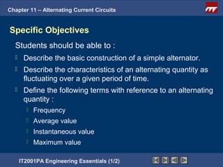
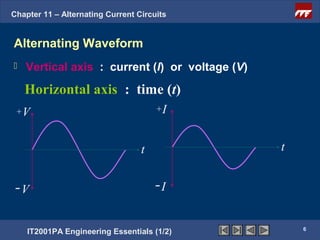
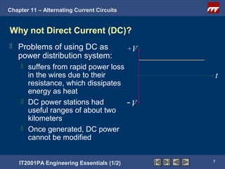
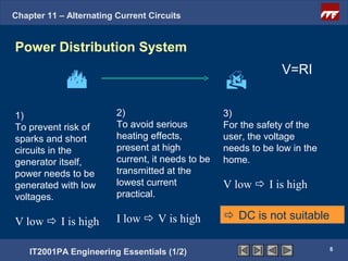
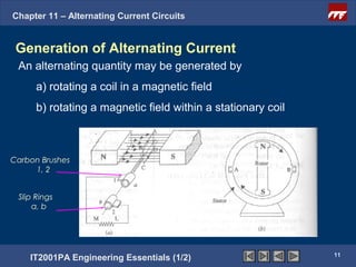
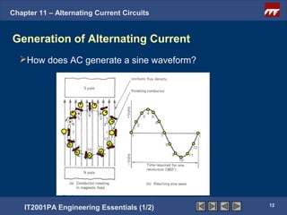
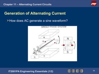
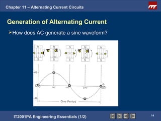
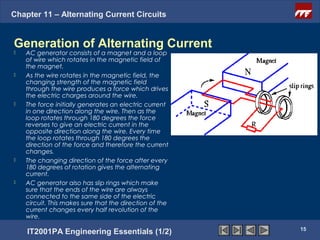
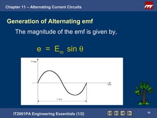
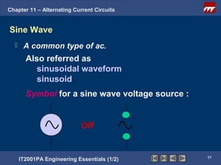
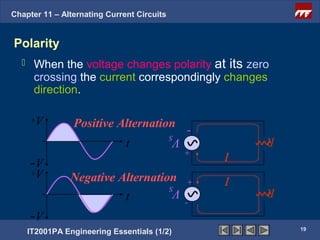
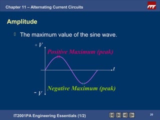
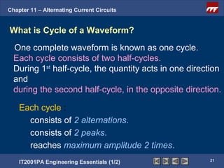
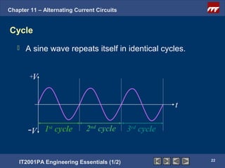
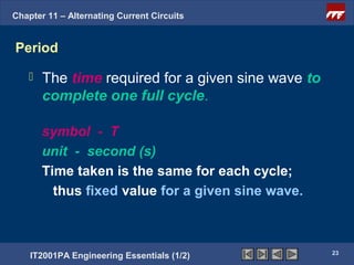
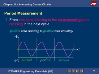
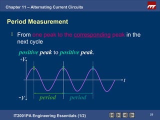
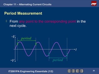
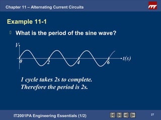
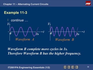
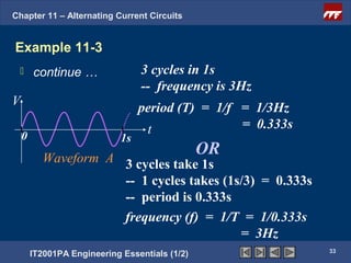
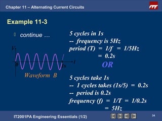
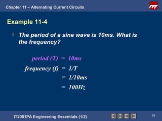
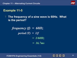
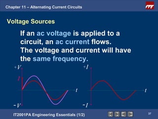
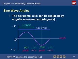
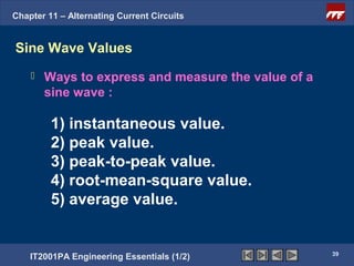
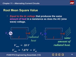
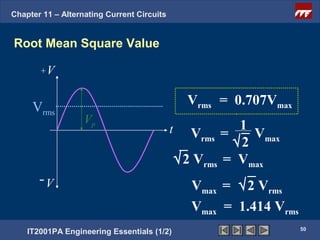
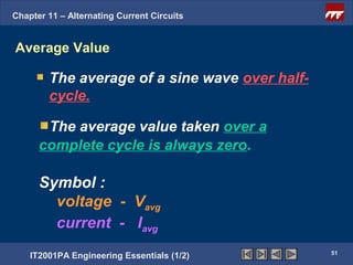
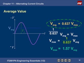
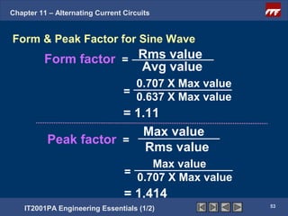
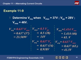
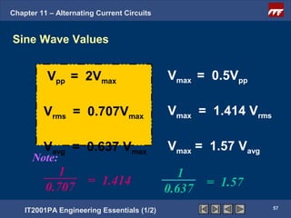
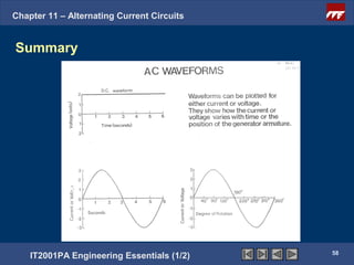

The document discusses alternating current circuits and provides learning objectives and specific objectives about alternating current waveforms. It defines key terms like frequency, amplitude, average value, maximum value, and root mean square value. It explains how an alternator generates a sine wave alternating current through a rotating coil in a magnetic field. The current periodically changes direction with each half rotation of the coil.


![Circuit Network Analysis - [Chapter4] Laplace Transform](https://cdn.slidesharecdn.com/ss_thumbnails/ch4-150613063858-lva1-app6891-thumbnail.jpg?width=640&height=640&fit=bounds)