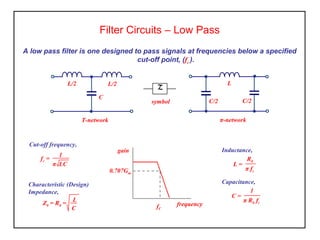
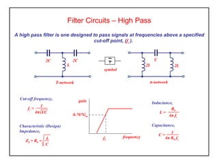
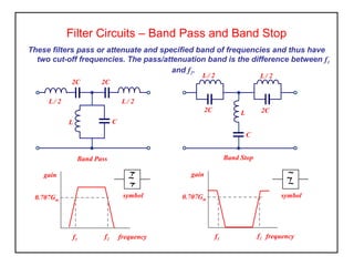
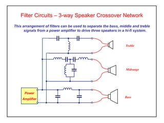
Filter Circuits – Low Pass
A low pass filter is one designed to pass signals at frequencies below a specified
cut-off point, (fc ).
frequency
gain
fC
0.707Gm
~~
symbol
T-network
L/2 L/2
C
π-network
C/2 C/2
L
fc =
1
π LC
Cut-off frequency,
Characteristic (Design)
Impedance,
Z0 = R0 =
L
C
L =
R0
π fc
Inductance,
C =
1
π R0 fc
Capacitance,
Filter Circuits – High Pass
frequency
gain
fC
0.707Gm
A high pass filter is one designed to pass signals at frequencies above a specified
cut-off point, (fc ).
~~
symbol
T-network
2C
L
2C
π-network
2L 2L
C
fc =
1
4π LC
Cut-off frequency,
Characteristic (Design)
Impedance,
Z0 = R0 =
L
C
L =
R0
4π fc
Inductance,
C =
1
4π R0 fc
Capacitance,
Filter Circuits – Band Pass and Band Stop
frequency
gain
f1
f2
0.707Gm
symbol
~
~
~
These filters pass or attenuate and specified band of frequencies and thus have
two cut-off frequencies. The pass/attenuation band is the difference between f1
and f2.
Band Pass
L
L/ 2
2C
L/ 2
2C
C
Band Stop
L
L/ 2
2C
L/ 2
2C
C
symbol
~
~
~
frequency
gain
f1
f2
0.707Gm
Filter Circuits – 3-way Speaker Crossover Network
This arrangement of filters can be used to separate the bass, middle and treble
signals from a power amplifier to drive three speakers in a hi-fi system.
Power
Amplifier
Bass
Treble
Midrange
Filter Circuits
Activity
1. A high pass filter is required to pass all frequencies above 5kHz and to have
a design impedance of 600Ω. Calculate the circuit values for both T- and π-
sections and sketch filters.
2. A low pass filter is required having a characteristic impedance at zero
frequency of 400Ω and a cut-off frequency of 600Hz. Calculate the circuit
values for both T- and π- sections and sketch the filters.
Filter Networks – Summary
• Low-pass and high-pass filters have one pass band and one cut-off
frequency.
• Band pass filters have one pass band and two cut-off frequencies.
• Band stop filters have two pass bands and two cut-off frequencies.
• The input impedance of the filter is called the characteristic impedance and
must be matched to the source.

Elect principles 2 filter networks

  • 1.
    Filter Circuits –Low Pass A low pass filter is one designed to pass signals at frequencies below a specified cut-off point, (fc ). frequency gain fC 0.707Gm ~~ symbol T-network L/2 L/2 C π-network C/2 C/2 L fc = 1 π LC Cut-off frequency, Characteristic (Design) Impedance, Z0 = R0 = L C L = R0 π fc Inductance, C = 1 π R0 fc Capacitance,
  • 2.
    Filter Circuits –High Pass frequency gain fC 0.707Gm A high pass filter is one designed to pass signals at frequencies above a specified cut-off point, (fc ). ~~ symbol T-network 2C L 2C π-network 2L 2L C fc = 1 4π LC Cut-off frequency, Characteristic (Design) Impedance, Z0 = R0 = L C L = R0 4π fc Inductance, C = 1 4π R0 fc Capacitance,
  • 3.
    Filter Circuits –Band Pass and Band Stop frequency gain f1 f2 0.707Gm symbol ~ ~ ~ These filters pass or attenuate and specified band of frequencies and thus have two cut-off frequencies. The pass/attenuation band is the difference between f1 and f2. Band Pass L L/ 2 2C L/ 2 2C C Band Stop L L/ 2 2C L/ 2 2C C symbol ~ ~ ~ frequency gain f1 f2 0.707Gm
  • 4.
    Filter Circuits –3-way Speaker Crossover Network This arrangement of filters can be used to separate the bass, middle and treble signals from a power amplifier to drive three speakers in a hi-fi system. Power Amplifier Bass Treble Midrange
  • 5.
    Filter Circuits Activity 1. Ahigh pass filter is required to pass all frequencies above 5kHz and to have a design impedance of 600Ω. Calculate the circuit values for both T- and π- sections and sketch filters. 2. A low pass filter is required having a characteristic impedance at zero frequency of 400Ω and a cut-off frequency of 600Hz. Calculate the circuit values for both T- and π- sections and sketch the filters.
  • 6.
    Filter Networks –Summary • Low-pass and high-pass filters have one pass band and one cut-off frequency. • Band pass filters have one pass band and two cut-off frequencies. • Band stop filters have two pass bands and two cut-off frequencies. • The input impedance of the filter is called the characteristic impedance and must be matched to the source.
  • 7.
    Filter Networks –Summary • Low-pass and high-pass filters have one pass band and one cut-off frequency. • Band pass filters have one pass band and two cut-off frequencies. • Band stop filters have two pass bands and two cut-off frequencies. • The input impedance of the filter is called the characteristic impedance and must be matched to the source.