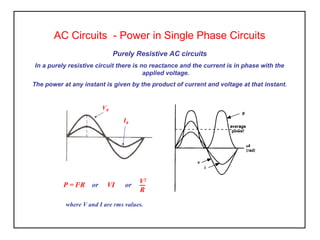
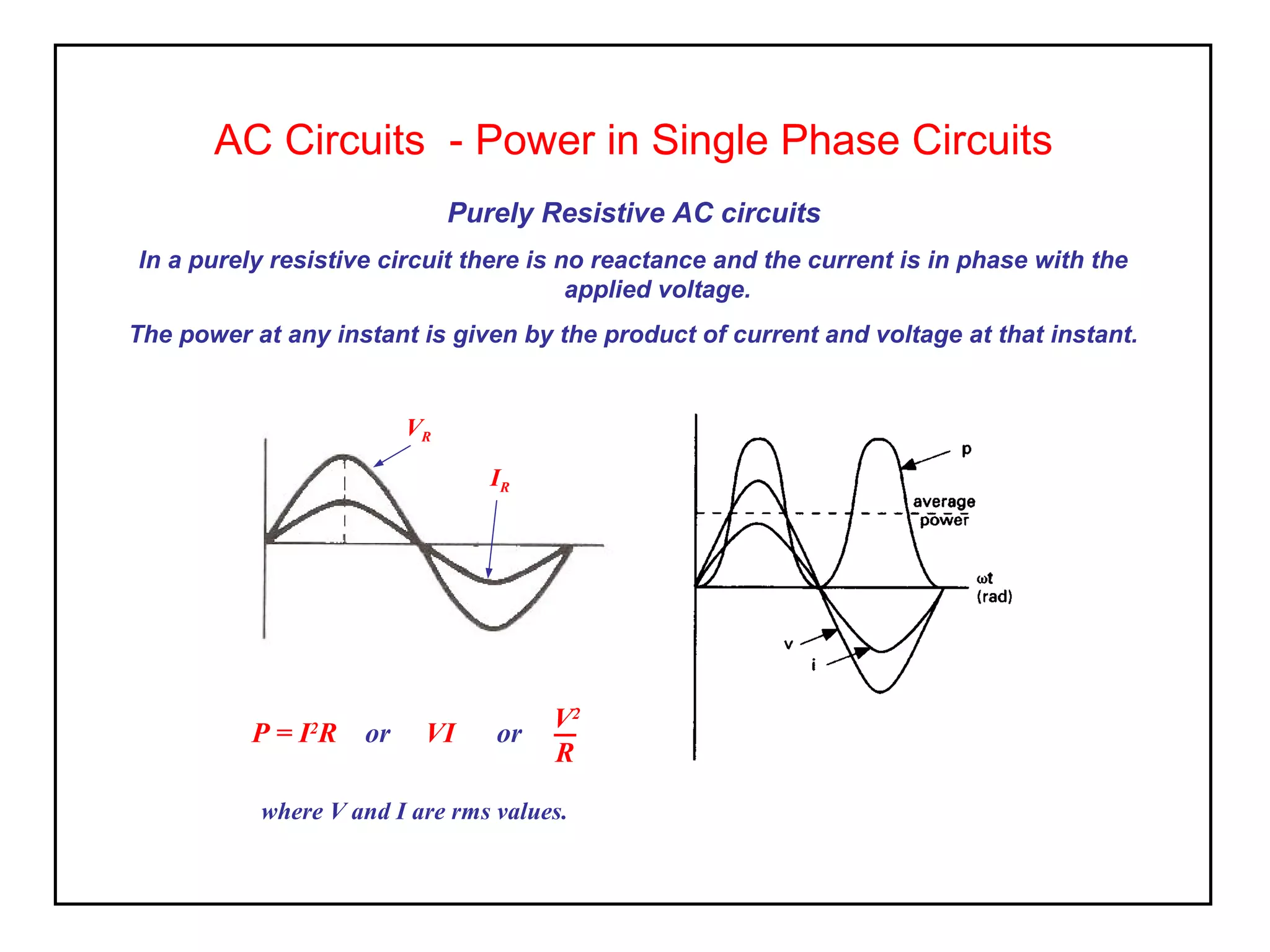
1) In purely resistive AC circuits, the current is in phase with the applied voltage. The power is given by the product of the rms current and voltage.
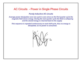
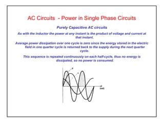
2) In purely inductive and capacitive circuits, the average power over a cycle is zero as the energy stored during one quarter cycle is returned during the next quarter cycle, so no net power is consumed.
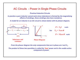
3) Practical inductive circuits contain both inductance and resistance. The power consumed is given by the product of the current and voltage drop across the resistor, which are in phase. This power is known as the "true" power.