Downloaded 60 times
![AC circuits -- Impedance
• Impedance and Ohm’s Law for AC:
– Impedance is Z = R + jX,
where j = -1, and X is the reactance in [].
– Ohm’s AC Law in s domain: v = i Z
• Resistance R dissipates power as heat.
• Reactance X stores and returns power.
– Inductors have positive reactance Xl=L
– Capacitors have negative reactance Xc=-1/C](https://image.slidesharecdn.com/diplomaiboeeu-3accircuitanalysis-150115224722-conversion-gate01/75/Diploma-i-boee-u-3-ac-circuit-analysis-14-2048.jpg)

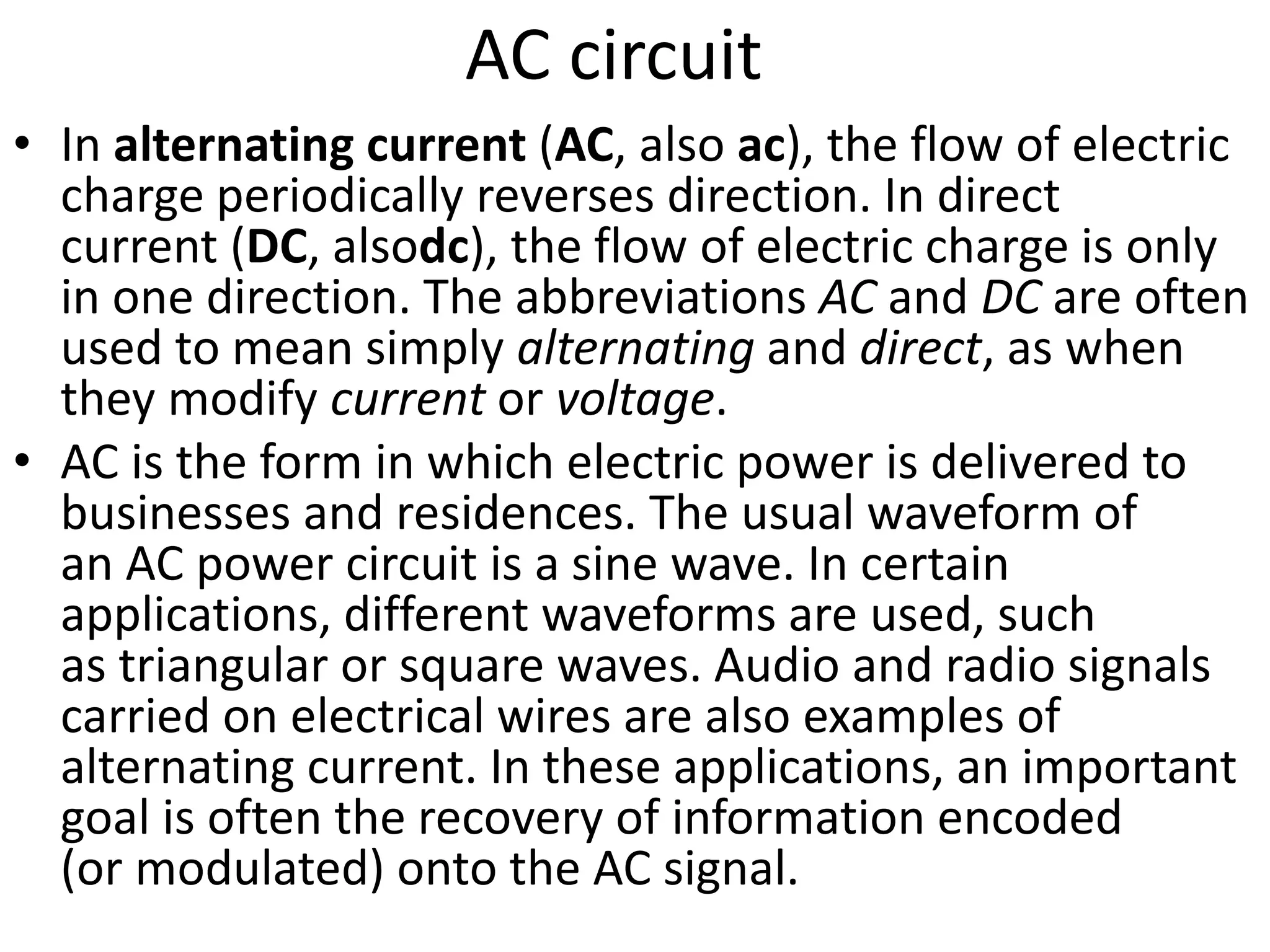
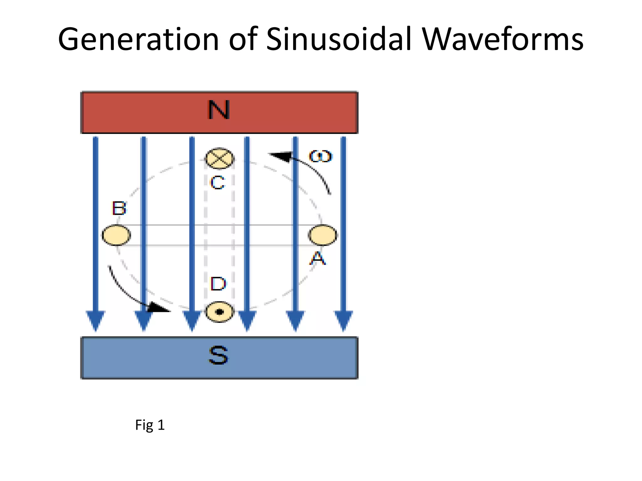
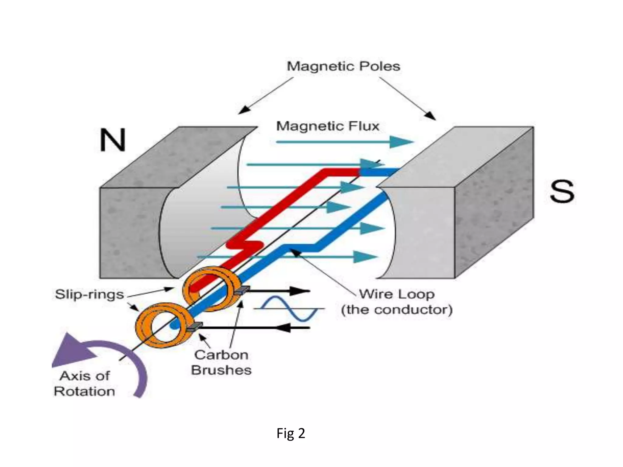
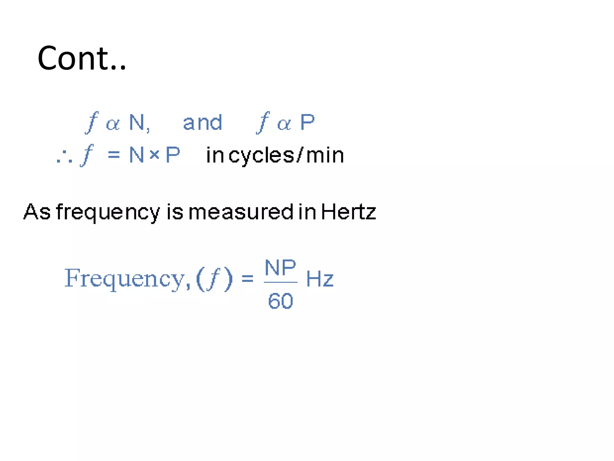
This document provides information about AC circuit analysis including: 1) AC current periodically reverses direction while DC flows in one direction. AC power is delivered to homes and businesses as a sine wave. 2) A simple generator consists of a coil rotating in a magnetic field, inducing a sinusoidal waveform. One cycle is produced per coil revolution. 3) The frequency of an AC generator output depends on the coil rotation speed and number of magnetic pole pairs. Higher speeds or more pole pairs increases frequency.