Downloaded 153 times


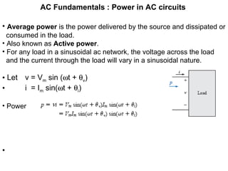
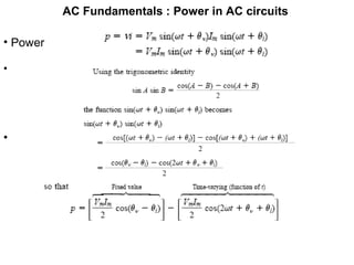
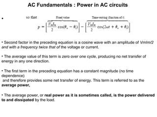
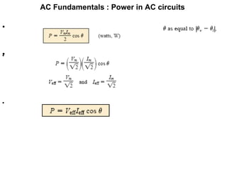


This document discusses the fundamentals of power in AC circuits, highlighting concepts such as average power, reactive power, and apparent power. It explains the relationship between voltage, current, and phase angle, emphasizing the importance of the power factor in understanding power delivery. Additionally, it describes how different load types (resistive, inductive, and capacitive) affect power transfer and the significance of reactive power in AC circuit analysis.