ABSTRACT: The performance characteristics of transonic aircraft majorly depend on the compressor rotor blade efficiency and engine weight. To increase rotor blade efficiency flow separation over rotor blade must be prevented and controlled. The aim was to modify and control the flow behaviour over compressor rotor blade by using three different boundary layer control techniques i.e suction, blowing and combination of suction and blowing and compare the effect of these three methods on flow around rotor blade. Rotor blade geometry has been modelled in CATIA V5 and then one suction surface and one blowing surface has been created on the blade surface. These geometries have been imported to ANSYS CFX 14.5 for computational simulation and analysis of rotor blade flow with these three techniques and without boundary layer control technique. Suction slot has been applied at the trailing edge of the suction surface and blowing slot has been applied at 55% of the blowing surface and shear stress transport model has been used for computational analysis. Two mass flow rates of 1kg/s and 1.5kg/s have been used here for boundary layer control method and boundary layer separation effects have been observed and this could be readily seen as the reattachment of velocity vectors which prevented the flow separation and increment in pressure ratio has been found to be 0.052, 0.09 and 0.12 for suction, blowing and combination of these two methods respectively.
lift augmentation devices for education purpose to understand and how its work to avoid the boundary layer separation
thanks to royal air force and air cadets the next generation
lift augmentation devices for education purpose to understand and how its work to avoid the boundary layer separation
thanks to royal air force and air cadets the next generation
Nomenclature and classification of controls in an airplane (slide # 3-4).
Which are the aerodynamic forces acting on airplane (slide # 5).
Working principle of an airplane (slide # 6).
How an airplane flies (basic motions of an airplane) (slide # 7).
How controls play their roles in these motions (slide # 8-22).
Simulate a flight in Cessna Skyhawk (slide # 23-28).
References and Questions & answers (slide # 30).
Numerical Investigation of Single Stage of an Axial Flow Compressor for Effec...IJERA Editor
In present work, a compressor configuration is taken from literature which will be studied for aspect ratio (ratio between length of blade to chord length) influence over performance. Performance in the sense is pressure ratio of compressor. The aspect ratio of the blade is an important parameter and has a strong influence on the performance of axial flow compressor. There are so many literatures available on influence of design parameters of axial flow compressor over its performance. Few literatures only are available for effects of aspect ratio of blade over performance of compressor. A study is proposed to be carried out to verify the effect of aspect ratio on the performance of single stage subsonic compressor through ANSYS-CFX software. The analysis will be carried out for the constant tip diameter of the compressor rotor blade having an aspect ratio 1, 2 and 3 and to obtain the pressure loss and flow parameters of the compressor stage. Further increase in aspect ratio will lead to structural problem of compressor. Therefore, there will be optimum aspect ratio between 2 and 3. Simulation will be conducted to aspect ratios of 2.1, 2.2, 2.3, 2.4, 2.5, 2.6, 2.7, 2.8 and 2.9 to find optimum ratio using ANSYS-CFX commercial CFD software.
Effect of tip clearance on performance of a centrifugal compressoreSAT Journals
Abstract The centrifugal compressor is to study the effect of tip clearance on the performance characteristics and the wall static pressure for a different flow co-efficient. The method of testing the compressor is run at a constant speed at 2000rpm. The tip clearance is varied by using spacers. The volume flow rate is varied with the help of throttling device to conduct the performance test. The performance characteristic of the centrifugal compressor showing the variation of discharge pressure with volume flow rate is plotted. Obtaining the performance characteristics showing the variation of discharge pressure with volume flow rate for different tip clearance, viz. =2.2%, 4%, 6.1% and 7.9%. Measurement of periodic pressure at various tip clearance viz. =2.2%, 4%, 6.1% and 7.9%. For each tip clearance pressure measured in radial location of impeller at 6 positions for different flow co efficient values. Five flow coefficients viz., ф =0.40, =0.34 (both above design flow), =0.28 (near design flow), =0.21=0.18 (both below design flow) and four values of non-dimensional tip clearance viz., =2.2%, 4%, 6.1% and 7.9%, are chosen for experimental work. The objective of the research work is to measure the periodic variation static pressure on the casing over the rotor at different values of tip clearance and flow coefficients. With the availability of these data, it is possible to improve the tip clearance flow in centrifugal compressor.
IJRET : International Journal of Research in Engineering and Technology is an international peer reviewed, online journal published by eSAT Publishing House for the enhancement of research in various disciplines of Engineering and Technology. The aim and scope of the journal is to provide an academic medium and an important reference for the advancement and dissemination of research results that support high-level learning, teaching and research in the fields of Engineering and Technology. We bring together Scientists, Academician, Field Engineers, Scholars and Students of related fields of Engineering and Technology.
IJRET : International Journal of Research in Engineering and Technology is an international peer reviewed, online journal published by eSAT Publishing House for the enhancement of research in various disciplines of Engineering and Technology. The aim and scope of the journal is to provide an academic medium and an important reference for the advancement and dissemination of research results that support high-level learning, teaching and research in the fields of Engineering and Technology. We bring together Scientists, Academician, Field Engineers, Scholars and Students of related fields of Engineering and Technology
Cfd simulation of single stage axial flow compressor for varying blade aspect...eSAT Journals
Abstract The aspect ratio of blade is an important parameter and has a strong influence on the performance of axial flow compressor. The performance of axial flow compressors is known to be affected by the choice of aspect ratio (the ratio of blade height to axial chord length). A study has been carried out to verify the effect of aspect ratio on the performance of 1.2 pressure ratio single stage subsonic compressor through AxStream analysis using Axial flow compressor design. The analysis has been carried out for the constant tip diameter of the compressor rotor blade having an aspect ratio 1, 2 and 3 and obtained the pressure loss and flow parameters of the compressor stage. This paper shows that the best operating conditions occur for the aspect ratio between 2 and 3. Keywords: Axial flow compressor, Aspect ratio, Computational Fluid Dynamic, AxStream
Knowledge Based Design of Axial Flow CompressorIJERA Editor
In the aerospace industry with highly competitive market the time to design and delivery is shortening every day. Pressure on delivering robust product with cost economy is in demand in each development. Even though technology is older, it is new for each customer requirement and highly non-liner to fit one in another place. Gas turbine is considered one of a complex design in the aircraft system. It involves experts to be grouped with designers of various segments to arrive the best output. The time is crucial to achieve a best design and it needs knowledge automation incorporated with CAD/CAE tools. In the present work an innovative idea in the form of Knowledge Based Engineering for axial compressor is proposed, this includes the fundamental design of axial compressor integrated with artificial intelligence in the form of knowledge capturing and programmed with high level language (Visual Basis.Net) and embedded into CATIA v5. This KBE frame work eases out the design and modeling of axial compressor design and produces 3D modeling for further flow simulation with fluid dynamic in Ansys-Fluent. Most of the aerospace components are developed through simulation driven product development and in this case it is established for axial compressor.
Design and Development of Transonic Axial Flow Compressor Rotor BladeIJERDJOURNAL
Abstract:- This paper is about a new computational fluid dynamics developed for the transonic flow in a compressor rotor. Due to 3-Dimensional blade modification the arrangements satisfying the required boundary condition. Engine compressor towards distorted inflow has to be taken in account which is already in the design phase. Flow separation over the blade surface reduction and elimination can improve better aerodynamic, performance, efficiency and stall margin. NASA transonic rotor tip critical in baseline blade rotor performance energizing the low momentum boundary layer, controlling the inception of stall. A Profile generator are attached on the inner casing of the rotor ahead to the loading edge of the rotor and it is influenced on the overall performance which has been studied.
COMPUTATIONAL ANALYSIS OF FLUID FLOW THROUGH ROTATING VANELESS DIFFUSERIjripublishers Ijri
The main objective of the work is to analyze the behavior of the fluid flow through a rotating vaneless diffuser,
flow near wall conditions, performance characteristics and means to reduce the flow losses in a centrifugal
compressor. The project presents a numerical procedure to investigate the pressure distortion at
exit flow of impeller and flow fields around impeller blade and to validate computational results against experimental
data with various models. In rotating vane less diffuser, there are various concepts. The concept
of blade cut back is to be employed in back ward curved impeller to obtain the rotating vaneless diffuser,
which rotates with the speed of the centrifugal impeller and the performance parameters is to be compared
with the static vane less diffuser.
Influence of number of impeller and diffuser blades on the pressure recovery ...eSAT Journals
Abstract Impeller is a very important element in rotating devices to deliver energy to/from the fluid. The diffusers are essential for effective transformation of the kinetic power produced by the rotor in a centrifugal fan. Hence the flow in the impeller and diffuser passages is the important phenomenon in optimizing the performance. These impeller and diffuser flow passages are the most complex regions to predict the flow behavior. With the advanced development of Particle Image Velocimetry as well as convenient numerical CFD tools, it has become possible to reach at an accurate result well-matched with the real behavior of the flow. Hence, in this work moving mesh technique is used to get a numerical solution for the estimation of actual flow manner. Numerous research works have been done recently to get the physics of fluid flow through impeller and diffuser, both numerically and experimentally. But it is found from the literature that the study on the performance of the fan by changing the number of impeller and diffuser blades together in a combination has not been the emphasis of attention in these works. Hence a numerical analysis has been carried out in this paper to comprehensively lookout the fluid interaction in impeller-diffuser as well as to envisage the flow behavior of the fan by changing the number of impeller and diffuser blades together in combination. For the same number of impeller blades, it is found from the analysis that a higher static pressure rise coefficient is achieved at the outlet of the fan for smaller number of diffuser blades. It is also found that larger the number of impeller blades, larger is the static pressure rise coefficient for the same number of diffuser blades, hence performance gets improved. Key Words: Unsteady flow, Recirculation zone, Turbulence, Impeller vane, Diffuser vane, Static pressure rise.
Numerical Investigation of Flow Field Behaviour and Pressure Fluctuations wit...Mustansiriyah University
this present work, CFD numerical method is applied to analyses the flow field in
an axial flow pump qualitative and quantitative analyses. Qualitative analysis for these
parameters comprise static pressure variations, dynamic pressure variations, velocity magnitude,
turbulent kinetic energy, shear stress. Quantitative analysis including the pressure fluctuations in
frequency domain analysis under different operation conditions. Also, sliding mesh method and
turbulence model type k- epsilon are used. Various monitoring points are stalled in order to
analyses pressure fluctuation mechanism in the impeller blade. The numerical results revealed
that the flow field for pressure and velocity are increase start from the suction side of the pump
to discharge side. Also, the results found that the high pressure occurs at the discharge side
along the axial direction of the impeller. The maximum value of pressure fluctuations is
occurred at tip blade region due to high interaction flow at this particular area. Moreover, the
pressure decreases as flow rate in the pump increases. Additionally, the results shown that the
pressure fluctuations have four peaks and four valleys the similar impeller blades number.
Furthermore, there are different positive and negative pressure regions, the negative pressure
area occurs due to lower pressure zone at inlet impeller area and hence which can lead to cause
occurrence of cavitation in this specific area. The current numerical demonstration results can
help the researches for further axial flow pump design.
- A pneumatic can be thought of a large flexible mechanical structure that is moved by some sort of control system. The control system takes its input from human operator & translates this command into the motion of actuators, which move the mechanical structure. The high performance and highly powerful.
- Pneumatic operated pneumatic shaper machine is efficient machine which works by pneumatic power, inserted of crank & shaping link mechanism here pneumatic power is employed with quick return mechanism this system consist of ram, pneumatic cylinder, time circuit when air from compressor is send to double acting cylinder via solenoid valve, this valve will make the cylinder to move too & for as per the single from the timer. Time will be programmed with delay.
Modeling And Simulation Swash Plate Pump Response Characteristics in Load Sen...IJMERJOURNAL
ABSTRACT: Fluid Power is widely employed in applications required high loads such as tractors, cranes, and airplanes. In load sensing hydraulic systems, loads are controlled by adjusting a pump-valve arrangement. In this paper, the swash plate pump hydraulic characteristics will be determined, the pump and its fluid gains will be derived to obtain the pump overall transfer function. Firstly, the swash plate pump mechanism is analyzed and its dynamic model is constructed; the pump pressure and flow rate are plotted and the possible improvement is introduced. The load sensing unit parameters such as orifice width, orifice area, maximum passage area, and piston area at X and Y will be examined to identify their influence on the pump characteristics; and the optimum parameters will be introduced. All results are developed and simulated numerically.
Generation of Electricity Through A Non-Municipal Solid Waste Heat From An In...IJMERJOURNAL
ABSTRACT: Energy production, waste disposal, and pollution minimization are key problems that must be addressed for sustainable cities of the environment. Waste management has become a major concern worldwide, and incineration is now being used increasingly to treat waste that cannot be recycled economically. The total heat content of non- municipal waste varies from countries to countries. The tonnage of generation in Nigeria is expected to soar over the next few years and the exploitation of this renewable energy locked up in urban solid municipal waste into grid energy can be taken advantage off.The heat generated from this incinerated plant can be used to generate electricity which will reduce overdependence on fossil fuel and the use of generator which in turn reduces pollution disposal of this waste is incinerated plant for the production of electricity. Hence, this paper intends to review the nonmunicipal waste potential in Nigeria, evaluate its environment and economic cost, and energy content of municipal solid waste deposits in Nigeria.
A New Two-Dimensional Analytical Model of Small Geometry GaAs MESFETIJMERJOURNAL
ABSTRACT : In this paper, a simple and exact analytical model for Small Geometry GaAs MESFET is developed to determine the potential distribution along the channel of the device. The model is based on the exact solution of two-dimensional Poisson’s equation in the depletion region under the gate. Then the obtained model is used to study the channel potential and threshold voltage of the device. Using the analytical model, the effect of the device parameter and bias conditions on performance of the device is investigated. The obtained results are graphically exhibited and discussed. In order to verification of the analytical results, TCAD device simulator is used and good accordance is observed.
Design a WSN Control System for Filter Backwashing ProcessIJMERJOURNAL
ABSTRACT: Day by day, there is a higher rate of need for accurate automation system to be used in industries and environment monitoring and control. In water treatment plants during the filtration phase, there is a process called backwashing, which particles suspended in the filter basin are removed. in this process the water are forcedly pumped through the filter in upward direction at enough speed to expand the filter media. Therefore, various types of valves used, which are opened and closed in a time sequencing manner. The paper proposed an automation control system for the backwashing process to be initiated and completed automatically using PLC, level sensors and valves installed inside the filter basin. Practically, a control system has been applied which all valves are opened and closed according to wireless signals coming from PLCs on its suitable time. In summary, the control in the process demonstrated that the proposed system is efficient, effective, and able to be reliable. Besides, the results increase the productivity at a low-cost mode.
Application of Customer Relationship Management (Crm) Dimensions: A Critical ...IJMERJOURNAL
ABSTRACT”: Customer relationship management is crucial due to the competitive environment. For this reason, it has become a widely implemented strategy across the hotel industry in retaining customers and maintaining good relationships with them. It also promotes customer satisfaction and loyalty which lead to the achievement of competitive business performance. However, due to the ever-increasing competition and the continuous changing customers’ needs in the hotel industry, the ability to achieve customer satisfaction is becoming a major challenge. Using 40 respondents from 20 hotels, this paper, therefore, explores the managers’ perspective into how the application of CRM dimensions impact on the performance of hotels and also examines the relationships between them since studies evaluating their relationships are limited. It studies CRM from the hotels’ perceptive as Guest Services Managers and Marketing Managers were the respondents. This study employed an exploratory research design and quantitative technique. The survey was conducted in New Delhi and simple random sampling was the sampling technique used to select respondents. With the study’s objectives in mind, the developed research hypotheses constructed were tested using multiple regression analysis as the statistical tool. Through the results, it has been revealed that CRM dimensions are positively related to the performance of hotels. Finally, CRM dimensions are highly recommended as a competitive strategic tool to enhance competitiveness.
Comparisons of Shallow Foundations in Different Soil ConditionIJMERJOURNAL
ABSTRACT: Soil is considered by the engineer as a complex material produced by weathering of the solid rock. Footings are structural elements that transmit column or wall loads to the underlying soil below the structure. Footings are designed to transmit these loads to the soil without exceeding its safe bearing capacity. Each building demands the need to solve a problem of foundation on different types of soil. The main aim of this project is to design the appropriate foundation as per size and shape on cohesive, non-cohesive and rocky soil. In this paper different foundation are studied for a middle side and corner column of a building with different bearing capacities. Based on the study and judicial judgment the type of foundation is decided as per depth, quantity of steel and quantity of concrete and try to find which shape of the foundation is more stable, economical and ways to reduce the ease of construction of the building
Place of Power Sector in Public-Private Partnership: A Veritable Tool to Prom...IJMERJOURNAL
ABSTRACT: Public Private Partnership involves private sector engagement in infrastructural development. Though in the past, the country infrastructure had been experiencing a decline in the system, this is because, government had been the sole contributor to infrastructural finance and had often taken responsibility for implementation, operations and maintenance as well. This decline in the system is caused by escalating population growth depending on available infrastructure, decaying of existing power infrastructure, political instability and corruption in the system. The ongoing reform is about bringing the system to a lime light. Hence, Public Private Partnership participation in the infrastructural development in Nigeria, will create favorable environment for an investors, provide job opportunities, long time policy, decision making and efficient use of the available resources. This paper therefore dwells on overview of the public private partnership with regards to energy and other infrastructural development of Nigeria. Challenges of the partnership and possible solutions towards subduing the problems are proffered.
Study of Part Feeding System for Optimization in Fms & Force Analysis Using M...IJMERJOURNAL
ABSTRACT: This paper describes the development of a flexible and vibratory bowl feeding system which is suitable for use in a flexible manufacturing system. The vibratory bowl feeder for automatic assembly, presents a geometric model of the feeder, and develops force analysis, leading to dynamical modeling of the vibratory feeder. Based on the leaf-spring modeling of the three legs of the symmetrically arranged bowl of the feeder, and equating the vibratory feeder to a three-legged parallel mechanism, the paper reveals the geometric property of the feeder. The effects of the leaf-spring legs are transformed to forces and moments acting on the base and bowl of the feeder. Resultant forces are obtained based upon the coordinate transformation, and the moment analysis is produced based upon the orthogonality of the orientation matrix. This reveals the characteristics of the feeder, that the resultant force is along the z-axis and the resultant moment is about the z direction and further generates the closed-form motion equation.
Investigating The Performance of A Steam Power PlantIJMERJOURNAL
ABSTRACT: The performance analysis of Shobra El-Khima power plant in Cairo, Egypt is presented based on energy and exergy analysis to determine the causes , the sites with high exergy destruction , losses and the possibilities of improving the plant performance. The performance of the plant was evaluated at different loads (Full, 75% and, 50 %). The calculated thermal efficiency based on the heat added to the steam was found to be 41.9 %, 41.7 %, 43.9% , while the exergetic efficiency of the power cycle was found to be 44.8%, 45.5% and 48.8% at max, 75% and, 50 % load respectively. The condenser was found to have the largest energy losses where (54.3%, 55.1% and 56.3% at max, 75% and, 50 % load respectively) of the added energy to the steam is lost to the environment. The maximum exergy destruction was found to be in the turbine where the percentage of the exergy destruction was found to be (42%, 59% and 46.1% at max, 75% and, 50 % load respectively). The pump was found to have the minimum exergy destruction. It was also found that the exergy destruction in feed water heaters and in the condenser together represents the maximum exergy destruction in the plant (about 52%). This means that the irreversibilities in the heat transfer devices in the plant have a significant role on the exergy destruction. So, it is thought that the improvement in the power plant will be limited due to the heat transfer devices.
Study of Time Reduction in Manufacturing of Screws Used in Twin Screw PumpIJMERJOURNAL
ABSTRACT: This paper gives the characteristics of Time reduction in manufacturing of screws for Twin screw pumps. Screws are playing a vital role in the performance of pumps, because pumps give the fluids transfer rate with the help of screws. There is a gap in screws which shows its positiveness. This indicates that we are studying about positive displacements pumps. Positive displacements pumps having no point of contact between screws, because of that there will be no any friction formation. Automation is best for development of product to reduce time in manufacturing of any product. In this paper we also tried to explain this feature of Automation to help reduction of time to manufacture of product to increase productivity.
Mitigation of Voltage Imbalance in A Two Feeder Distribution System Using IupqcIJMERJOURNAL
ABSTRACT: Proliferation of electronic equipment in commercial and industrial processes has resulted in increasingly sensitive electrical loads to be fed from power distribution system which introduce contamination to voltage and current waveforms at the point of common coupling of industrial loads. The unified power quality conditioner (UPQC) is connected between two different feeders (lines), hence this method of connection of the UPQC is called as Interline UPQC (IUPQC).This paper proposes a new connection for a UPQC to improve the power quality of two feeders in a distribution system. Interline Unified Power Quality Conditioner (IUPQC), specifically aims at the integration of series VSC and Shunt VSC to provide high quality power supply by means of voltage sag/swell compensation, harmonic elimination in a power distribution network, so that improved power quality can be made available at the point of common coupling. The structure, control and capability of the IUPQC are discussed in this paper. The efficiency of the proposed configuration has been verified through simulation using MATLAB/ SIMULINK.
Adsorption of Methylene Blue From Aqueous Solution with Vermicompost Produced...IJMERJOURNAL
ABSTRACT: The removal of Methylene blue as a synthetic dye from aquatic system was investigated by using vermicompost. The dye concentration, contact time and pH of the solution carried out in the adsorption studies. Batch adsorption experimental data were suitable for the Langmuir isotherm and a very good fit to the second order kinetic model (pH=10). The maximum adsorption capacity calculated 256.66 mg g-1 . Vermicompost and the dye loaded vermicompost were characterized by SEM and FTIR. It was found that the vermicompost is stable without losing their activity.
Analytical Solutions of simultaneous Linear Differential Equations in Chemica...IJMERJOURNAL
ABSTRACT: Analytical method for solving homogeneous linear differential equations in chemical kinetics and pharmacokinetics using homotopy perturbation method has been proposed. The mathematical model that depicts the pharmacokinetics is solved. Herein, we report the closed form of an analytical expression for concentrations species for all values of kinetic parameters. These results are compared with numerical results and are found to be in satisfactory agreement. The obtained results are valid for the whole solution domain.
Experimental Investigation of the Effect of Injection of OxyHydrogen Gas on t...IJMERJOURNAL
ABSTRAC: Oxy-Hydrogen gas, H2O2, is a mixture of hydrogen and oxygen produced by water electrolysis. In this work, an experimental exploration was carried out in order to study the effect of the addition of oxy-hydrogen gas into inlet air manifold on speed performance characteristics of a diesel engine at different operating conditions. The experimental work was performed on a test rig comprising a four stroke 5.67 liters water-cooled diesel engine and a Heenan hydraulic dynamometer. Instrumentation included devices for measuring engine speed, load, fuel consumption and inlet air flow rate. The measurements were conducted at 1000, 1500, 2000 and 2500 rpm. At each speed, the engine load was adjusted to 20%, 40% and 80% from the engine full load which corresponds to engine brake mean effective pressures of 1.55, 3.11, and 6.22 bar, respectively, for Oxy-hydrogen generator supplied Currents of 26A and electrolyte concentration of 25 %. The fuel saving percentage and so the brake thermal efficiency for the H2O2 enriched CI engine is more evidently seen at low loads and high-speed conditions. the volumetric efficiency drop was about 5 % at small speeds and reaches to about 2% at higher engine speed.
Hybrid Methods of Some Evolutionary Computations AndKalman Filter on Option P...IJMERJOURNAL
ABSTRACT: The search for a better option price continues within the financial institution. In pricing a put option, holders of the underlying stock always want to make the best decision by maximizing profit. We present an optimal hybrid model among the following combinations: Kalman Filter-Genetic Programming(KF-GP), Kalman Filter-Evolutionary Strategy(KF-ES) and Evolutionary Strategy -Genetic Programming(ES- GP). Our results indicate that the hybrid method involving Kalman Filter-Evolutionary Strategy(KF-ES) is the best model for any investor. Sensitivity analysis was conducted on the model parameters to ascertain the rigidity of the model.
An Efficient Methodology To Develop A Secured E-Learning System Using Cloud C...IJMERJOURNAL
ABSTRACT: Now-a-days, each and every action involved in our life becomes computerized in order to reduce the time, complexity and manual power. The education systems are also being computerized, to train the students in a much efficient way. This system is termed as E-Learning. E-Learning is an Internet-based learning process, in which the Internet technology is used to design, implement, manage and extend learning, which will improve the efficiency of learning. Learning, Teaching and Training are intensely connected components, which are all included in the development of E-Learning system. Cloud Computing provides an efficient platform to support the E-Learning systems, as it can be dramatically changes over time .In this paper, an overview on the new emerging E-Learning system , utilization of the SAAS (Software as a Service) and the methodology to test the efficiency of the person in a secured way are described.
Nigerian Economy and the Impact of Alternative Energy.IJMERJOURNAL
ABSTRACT: Nigeria is endowed with natural resources which are aim at developing the country.The need for alternative energy resources to drive the nation economy cannot be over-emphasized. The incessant power failure has grossly affected the economy, seriously slowing down development in rural and sub-rural settlement. A robust solution must be found to end the crises. Alternative energy source has the potential of solving power problem in Nigeria as well as providing safer and cleaner environment than the fossil fuel. This paper also examines the socio–economic benefits of the alternative energy (solar, wind, biomass, hydro and geothermal) to the nation economy and the utilization of the resources to meet human needs and the generation yet unborn and to provide sustainable development, thereby improve the standard of living and mitigating climate change.
ABSTRACT: Many writers describe empowerment as a process as opposed to a condition or state of being which is being a key feature of empowerment emphasized by many researchers. As a process empowerment becomes difficult to be measured by standard tools available to social scientists. As case study helps in bringing us to understand a complex issue or object and can extend experience or add strength to what is already known through previous research. Case studies also emphasized on detailed contextual analysis of a limited number of events or conditions and their relationships. Researcher had made use of this qualitative research method to examine contemporary real-life situations.
Validation of Maintenance Policy of Steel Plant Machine Shop By Analytic Hier...IJMERJOURNAL
ABSTRACT: In this paper the maintenance activities of the Machine shop of Steel plant have been considered. As maintenance is a routine activity to keep a machine at its normal operating condition so that it can deliver its expected performance without causing any loose of time on account of accidental damage or breakdown and maintenance is a recurring activity. So for reduction of maintenance cost and safety of the operator as well as the residents of nearby area it is better to decide which machines should go for which type of maintenance. For this decision AHP is used and the Expert choice software is used for that calculations and this paper is for the validation of results.
li-fi: the future of wireless communicationIJMERJOURNAL
ABSTRACT: Nowadays people and their electronic devices access wireless internet. But, clogged airwaves are going to make it increasingly difficult to latch onto a reliable signal. So, Radio waves are just one part of the spectrum that can carry our data. We can use “Data through Illumination”. In this process, the data is sent through an LED source that varies in intensity faster than the human eye could follow. The future can be envisioned where the data for laptops, smart phones and all other smart applications is transmitted through the light in our living room. And security would be a snap—if you can’t see the light, you can’t access the data.
KuberTENes Birthday Bash Guadalajara - K8sGPT first impressionsVictor Morales
K8sGPT is a tool that analyzes and diagnoses Kubernetes clusters. This presentation was used to share the requirements and dependencies to deploy K8sGPT in a local environment.
6th International Conference on Machine Learning & Applications (CMLA 2024)ClaraZara1
6th International Conference on Machine Learning & Applications (CMLA 2024) will provide an excellent international forum for sharing knowledge and results in theory, methodology and applications of on Machine Learning & Applications.
We have compiled the most important slides from each speaker's presentation. This year’s compilation, available for free, captures the key insights and contributions shared during the DfMAy 2024 conference.
Hierarchical Digital Twin of a Naval Power SystemKerry Sado
A hierarchical digital twin of a Naval DC power system has been developed and experimentally verified. Similar to other state-of-the-art digital twins, this technology creates a digital replica of the physical system executed in real-time or faster, which can modify hardware controls. However, its advantage stems from distributing computational efforts by utilizing a hierarchical structure composed of lower-level digital twin blocks and a higher-level system digital twin. Each digital twin block is associated with a physical subsystem of the hardware and communicates with a singular system digital twin, which creates a system-level response. By extracting information from each level of the hierarchy, power system controls of the hardware were reconfigured autonomously. This hierarchical digital twin development offers several advantages over other digital twins, particularly in the field of naval power systems. The hierarchical structure allows for greater computational efficiency and scalability while the ability to autonomously reconfigure hardware controls offers increased flexibility and responsiveness. The hierarchical decomposition and models utilized were well aligned with the physical twin, as indicated by the maximum deviations between the developed digital twin hierarchy and the hardware.
CHINA’S GEO-ECONOMIC OUTREACH IN CENTRAL ASIAN COUNTRIES AND FUTURE PROSPECTjpsjournal1
The rivalry between prominent international actors for dominance over Central Asia's hydrocarbon
reserves and the ancient silk trade route, along with China's diplomatic endeavours in the area, has been
referred to as the "New Great Game." This research centres on the power struggle, considering
geopolitical, geostrategic, and geoeconomic variables. Topics including trade, political hegemony, oil
politics, and conventional and nontraditional security are all explored and explained by the researcher.
Using Mackinder's Heartland, Spykman Rimland, and Hegemonic Stability theories, examines China's role
in Central Asia. This study adheres to the empirical epistemological method and has taken care of
objectivity. This study analyze primary and secondary research documents critically to elaborate role of
china’s geo economic outreach in central Asian countries and its future prospect. China is thriving in trade,
pipeline politics, and winning states, according to this study, thanks to important instruments like the
Shanghai Cooperation Organisation and the Belt and Road Economic Initiative. According to this study,
China is seeing significant success in commerce, pipeline politics, and gaining influence on other
governments. This success may be attributed to the effective utilisation of key tools such as the Shanghai
Cooperation Organisation and the Belt and Road Economic Initiative.
CHINA’S GEO-ECONOMIC OUTREACH IN CENTRAL ASIAN COUNTRIES AND FUTURE PROSPECT
Effect of Different Boundary Layer Control Techniques on the Flow of Compressor Rotor Blade
1. International
OPEN ACCESS Journal
Of Modern Engineering Research (IJMER)
| IJMER | ISSN: 2249–6645 www.ijmer.com | Vol. 7 | Iss. 5 | May. 2017 | 27 |
Effect of Different Boundary Layer Control Techniques on the
Flow of Compressor Rotor Blade
Navneet Kumar1
,Rohit Yadav2
Andkhushal Raj3
1,2,3
P.G. Student, Department Of Aerospace Engineering, Indian Institute Of Technology, Kanpur,
Uttarpradesh, India1
I. INTRODUCTION
Efficiency of aircraft gas turbine engines in transonic flow can be increased with the use of compressor
having multiple stages and high pressure ratio but this kind of configuration leads to increment in weight and
cost also. A lot of researches were done in this field and our aim is achieving high pressure ratio so that
efficiency of compressor can be increased. Performance of compressor blade in transonic flow which is partly
high subsonic and low supersonic is very important due to occurrence of shock wave which leads to flow
separation and this causes different type of losses and this will affect the performance of compressor and
therefore performance of engine also reduces. To avoid these losses and to prevent or delay separation different
methods like actuating devices, modification in geometry of axial fans etc. are used today and in this paper BL
control methods are used to delay or modify flow separation of blade.
To reduce the losses and delay or prevent separation caused by shock different kind of modifications
has been applied to the rotor blade model some of them are introducing plasma actuating devices on the trailing
edge of the blade, Boundary layer control methods such as suction, blowing etc. In the present study the flow
field of transonic axial compressor rotor blade has been numerically simulated to clarify the mechanism of
boundary layer control by suction, blowing and combination of these two methods simultaneously.
Axial compressors are designed and developed in such a manner that these could be used to operate
under steady axisymmetric flow, where pressure rise across compressor depends upon compressor mass flow
rate. In axial compressor flow enters the first blade and leaves axially which is parallel to the axis of shaft.
Higher mass flow rates give higher thrust. Axial compressor has lower pressure ratio per stage then the
centrifugal one. In transonic aircraft axial flow compressors have been used therefore to increase performance of
transonic aircraft pressure ratio across blades of the compressor should be high and to achieve this flow over the
blade needs to be modified.To prevent compressor flow instabilities different methods and devices are available
today. Methods like tiny grooves or slot on endwalls, casing treatments etc. have been employed to compressor
rotor blade in the late 1980s’. In Transonic flow performance is very important because this type of flow is
partly high subsonic and low supersonic which leads to the formation of shock and due to this losses increases
ABSTRACT: The performance characteristics of transonic aircraft majorly depend on the compressor
rotor blade efficiency and engine weight. To increase rotor blade efficiency flow separation over rotor
blade must be prevented and controlled. The aim was to modify and control the flow behaviour over
compressor rotor blade by using three different boundary layer control techniques i.e suction, blowing
and combination of suction and blowing and compare the effect of these three methods on flow around
rotor blade.
Rotor blade geometry has been modelled in CATIA V5 and then one suction surface and one blowing
surface has been created on the blade surface. These geometries have been imported to ANSYS CFX
14.5 for computational simulation and analysis of rotor blade flow with these three techniques and
without boundary layer control technique. Suction slot has been applied at the trailing edge of the
suction surface and blowing slot has been applied at 55% of the blowing surface and shear stress
transport model has been used for computational analysis.
Two mass flow rates of 1kg/s and 1.5kg/s have been used here for boundary layer control method and
boundary layer separation effects have been observed and this could be readily seen as the
reattachment of velocity vectors which prevented the flow separation and increment in pressure ratio
has been found to be 0.052, 0.09 and 0.12 for suction, blowing and combination of these two methods
respectively.
Keywords: Boundary Layer, Blowing, compressor, isentropic efficiency, Rotor blade, Pressure ratio,
Suction
2. Effect Of Different Boundary Layer Control Techniques On The Flow Of Compressor Rotor Blade
| IJMER | ISSN: 2249–6645 www.ijmer.com | Vol. 7 | Iss. 5 | May. 2017 | 28 |
and overall engine performance reduces. Compressor rotor blade geometry is very important because its
geometry decides where shock appears on the blade and therefore separation of flow depends on the blade
geometry.
1.1 Rotor Blade Specifications
Table 1 Properties of Rotor Blade
Design Pressure Ratio - 1.61
Mass flow rate - 32 kg/s
Rotational speed - 16000
Tip speed - 426 m/s
Solidity at the hub - 2.95
Solidity at the tip - 1.33
1.2 Boundary layer and losses
Boundary layer is the layer where flow is retarded due to significant viscosity effect and this layer play
key role in deciding performance parameters because flow separation depends on this layer and parameters like
pressure, entropy, temperature, viscous layer depends on flow separation. Early flow separation reduces the
performance of engines therefore boundary layer needs to be controlled to delay or prevent separation.
In this type of turbo machinery loss mechanism is divided into two groups i.e. Internal and Parasitic loss
mechanism. Internal is associated with the main flow through the compressor while parasitic is associated with
minor flow loss leaking away from major flow of the compressor. Major losses in transonic flow compressor are
as follows:
Shock
Blade loading and leakage
Clearance and profile
Annulus and secondary
1.3 Boundary Layer control methods
BL is the region where mass, momentum and heat transfer are felt and due to these flow is retarded and
undergoes various types of losses which reduces performance therefore BL control is necessary to achieve
desire performance. BL control refers to the controlling behaviour of fluid flow over rotor blades.
Suction, blowing and combination of suction and blowing methods are used simultaneously here as BL control
methods. In Suction method a suction surface and suction hole has been created on blade surface and which
helps in reenergizing the flow by sucking low energy fluid on the blade surface whereas in Blowing type
blowing surface and blowing hole has been created near half of the chord of blade surface through which high
energy fluid has been blown over the low energy fluid flow surfaces and this high energy fluid got mixed with
low energy fluid and as a result energy of previously fluid has been increased and flow over blade surfaces
becomes more smooth and separation has been delayed or prevented. Features of suction and blowing methods
are combined in one single method and then observing the effect of this combined method.
1.4 Equation
Isentropic efficiency
𝜂 =
𝑃𝑅
𝛾−1
𝛾 −1
𝑇2
𝑇1−1
…………………………… (1)
In the “equation 1” PR is the pressure ratio and 𝛾 is the specific heat ratio for air which has the standard
numerical value of 1.4. 𝑇2 &𝑇1 are the total temperatures of outlet and inlet respectively.
II. RELATED WORK
To increase the performance of transonic aircraft many researches has been made in this field. There
are various devices and methods available today to prevent compressor flow instabilities. Some of the methods
are casing treatment, tiny grooves or slots made on endwall etc. and these methods have been employed to
compressor rotor blade in the late 1970s’. Many methods like adding plasma actuating devices on the trailing
edge of blade, Boundary layer control by suction etc. have been developed to delay or prevent separation.
3. Effect Of Different Boundary Layer Control Techniques On The Flow Of Compressor Rotor Blade
| IJMER | ISSN: 2249–6645 www.ijmer.com | Vol. 7 | Iss. 5 | May. 2017 | 29 |
Features of suction and blowing method has been used separately on the rotor blade separately but not
at the same time. Before using these control surfaces in our geometry we have done a lot of literature survey to
get appropriate coordinates of rotor blade surface and we got these points from the researches made in 90’s.
Suction and blowing has been used in many other researches to prevent flow separation and these methods has
delayed flow separation and reduces the boundary layer effects especially on airfoils. Due to the occurrence of
shocks in transonic flow, Performance of compressor rotor has been decreased therefore researches has been
made in this field so that performance of the rotor could be increased by some means.
In the previous researches suction and blowing both methods has been used but in this research we
want to use features of both the methods at the same time and by this mean we want to avoid or delay flow
separation so that flow remain attached to the blade and velocity vectors should be smooth so that we got high
pressure ratio per stage. When suction method has been used in the previous researches then increment in
pressure ratio was not much effective and when blowing has been used then increment in pressure ratio was
more than suction therefore we got the idea of using both the methods at the same time to reduce compressor
instabilities and to increase performance of transonic axial compressor.
III. METHODOLOGY
3.1 Modelling
Modelling of rotor blades has been done in CATIA V5 (a software used for modelling and designing
any object).Modelling of compressor rotor blade is not an easy job due to complexity of curve i.e. it is twisted
from hub to tip, unless we do not have proper coordinates of points, blade modelling is not possible and these
coordinates of point can be obtained from literature survey of researches made in this field. First modelling of
single surface has been done by joining coordinates of four points and then formation of all surfaces of blade has
been done by joining coordinates of all the points then geometric model of blade is ready and after this casing
hubs and outer walls of blades has been modelled and this depends on the tip clearance chosen.
Table 2 Important parameters of Model
Maximum chord length 143.68
Maximum span 250.94
Inlet Diameter 202.362
Outlet Diameter 147.638
Tip Clearance 4.26
Figure1 Geometric model of rotor blades
There were thirty six blade in single rotor stage of compressor which has been shown in Figure1 and
number of elements corresponding to each blade was very high due to which this would take too much of
computational time and cost.
4. Effect Of Different Boundary Layer Control Techniques On The Flow Of Compressor Rotor Blade
| IJMER | ISSN: 2249–6645 www.ijmer.com | Vol. 7 | Iss. 5 | May. 2017 | 30 |
Figure2 Single blade model with outer walls and casing
To overcome this problem and to reduce our computational cost and time our model has been restricted
to single blade geometric model which has been shown below in Figure2 and results and analysis has been done
for this model only.
3.2 Grid and mesh parameters
3.2.1 Grid generation and mesh parameters without boundary layer control
Grid creation was very important phase in CFD simulations and if grid was of bad quality then our
results were not good. In this paper for shell meshing Quad dominant mesh type has been used and patch
dependent method has been used for obtaining this and for volume mesh tetra or mixed type mesh has been used
and robust method helps in achieving this.
After completion of geometric modelling in designing software CATIA V5 then geometry has been
imported to ICEM CFD 14.5 and parts has been created here and all parts were assigned a name. This parts
creation has been done because by doing this it was possible to create finer grids in some parts where flow
parameters were very important. In importing the model from CATIA to ICEM blade geometry has been
distorted therefore when all the parts has been created geometry should be repaired by providing tolerance to 0.1
and this tolerance has been selected on the basis of smallest length associated with the model. Once repairing
process has been done then delete the overlapped surfaces and any holes in the geometry and then model was
ready for grid generation. In importing geometry some surfaces were lost, some holes were appearing and
surfaces were overlapped also and to avoid this repairing process was required.After Repairing process body
should be created by selecting two points diagonally, by doing so fine mesh has been created on blade then the
outer wall and casing.
To consider boundary layer effects on the flow height was kept as constant and number of prism layers
has been calculated using Y+ calculators.
Figure3 Parameters setup for part mesh
5. Effect Of Different Boundary Layer Control Techniques On The Flow Of Compressor Rotor Blade
| IJMER | ISSN: 2249–6645 www.ijmer.com | Vol. 7 | Iss. 5 | May. 2017 | 31 |
First global mesh parameters has been defined and after this part mesh parameters has been defined which
has been shown in the above Figure3 In the part mesh setup different element sizes have been defined to create
coarsen mesh on the edge of the blade. When all the parameters have been defined then create prism layer and then
apply compute for generating mesh grids. Grid generation of single blade has been shown in Figure4 and Grid of
outer walls and casing has been shown in Figure5.
Table 3 Mesh parameters of Grids of model with and without blowing boundary layer control surface
Properties Without
boundary layer
control
With suction
BL control
With blowing BL
control
With Combination of
suction and blowing
simultaneously BL control
Initial Height 0.000169291 0.000169291 0.000169291 0.000169291
Total Height 0.0121949 0.0121949 0.0121949 0.0121949
Total Elements 1669986 1704628 1716482 1786968
Total Nodes 566300 579554 585573 610165
Figure4 Grid generation of blade on single blade model
Grid or mesh generation on the blade surfaces has been shown in Fig.4 and two different views has
been shown in this Fig. at the surface of blade grids were very fine because this was the domain where flow
behaviours were very important.
Figure5 Grid generation of blade on outer walls and casing
6. Effect Of Different Boundary Layer Control Techniques On The Flow Of Compressor Rotor Blade
| IJMER | ISSN: 2249–6645 www.ijmer.com | Vol. 7 | Iss. 5 | May. 2017 | 32 |
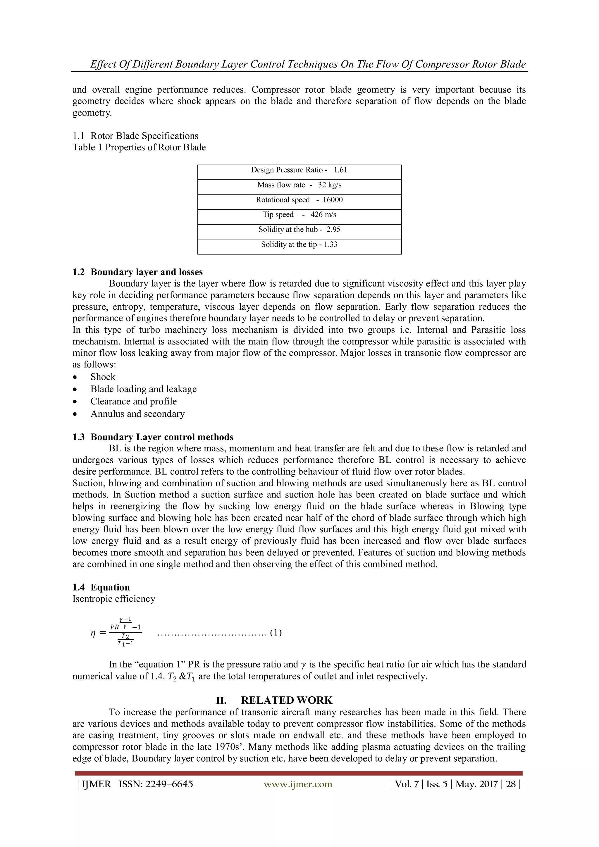
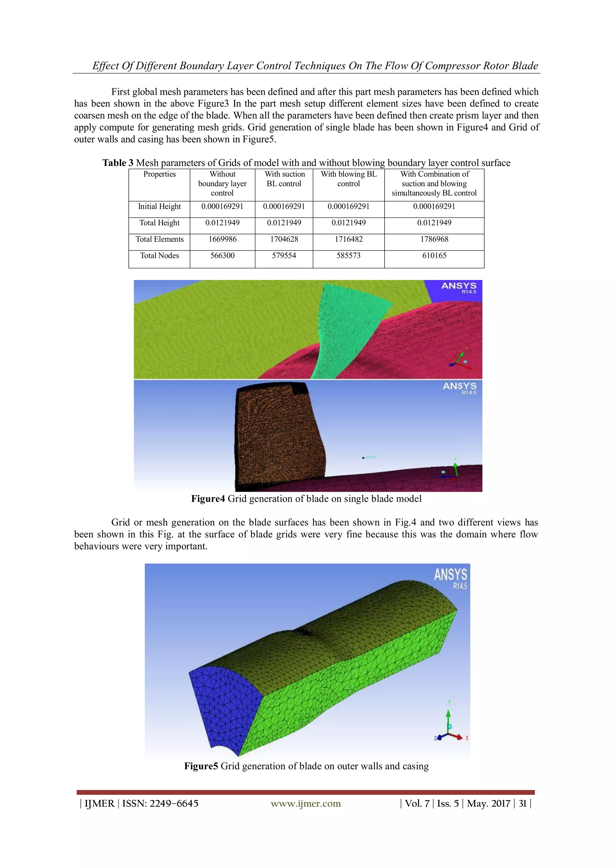
Grids formation on the geometry other than blade surface has been shown in the Figure5 and grids of these outer
walls and casings were not very fine because flow behaviour around these surfaces were out of our interest.
3.2.2Grid generation with boundary layer control surface
In the first method one new suction surface with suction hole have been employed in the blade
geometry and while creating parts one new part named as suction layer was created and in the blowing method
blowing surface with hole have been created and prism layer has been employed for both cases. All other steps
were similar to the previous section. In last method this geometry has two control surfaces and two holes. One
was suction surface and other was blowing surface and one was suction hole and other was blowing hole. In the
part creation method these surfaces were also assigned a name and prism layer were calculated for both suction
and blowing surface. Prism layers were applied to these surfaces because we want finer mesh on these surfaces
also and remaining steps to develop grids were similar to previous case.
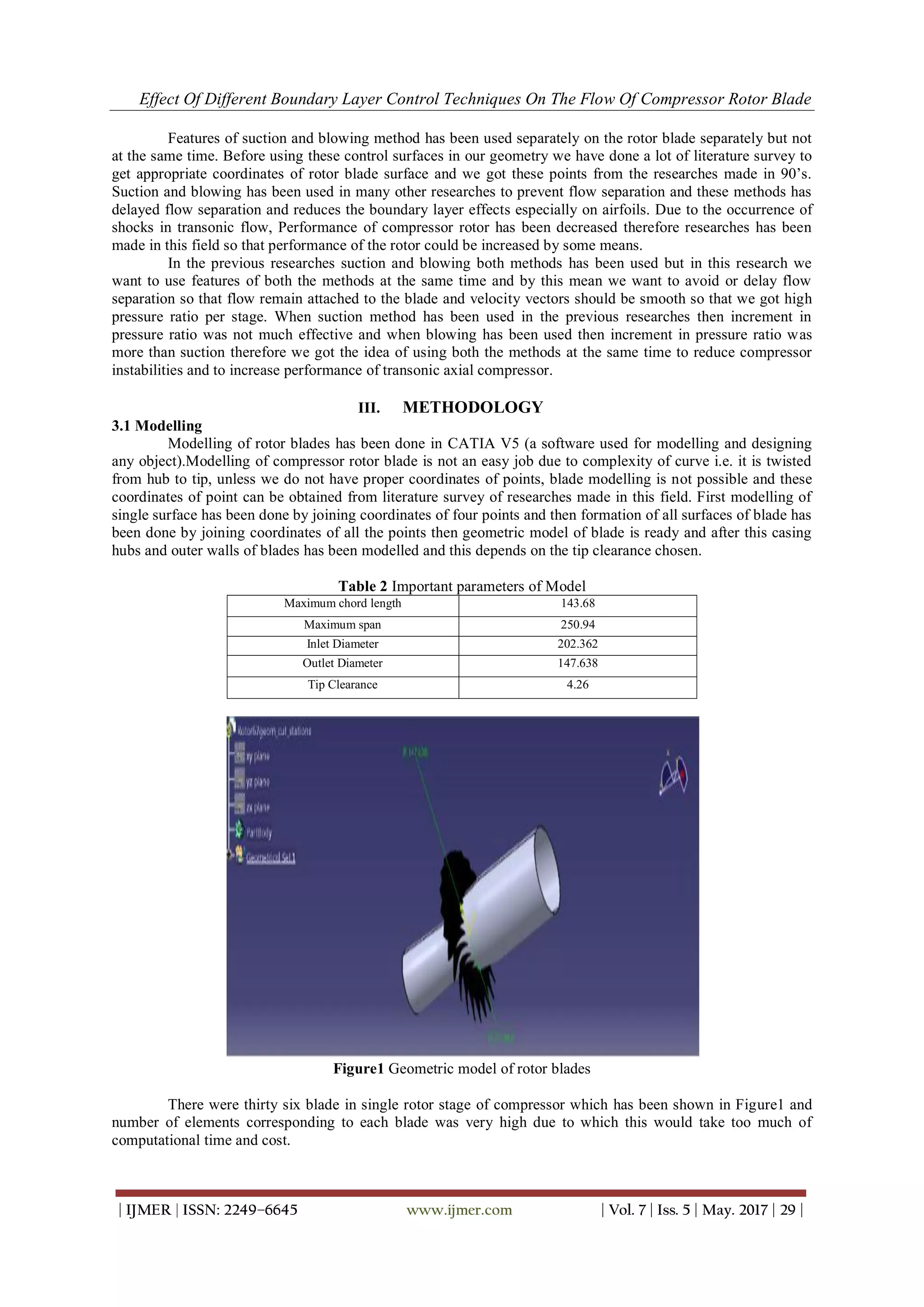
Figure6 Grid generation of blade model with control surfaces
Grid generation of control surfaces for all three methods has been shown in Fig.6 and on the suction and
blowing surface grids were very fine because we have more interest on the flow behaviour on these surfaces.
3.3 Boundary conditions for computational simulation
Computational Fluid Dynamics has been used to solve the model associated with the fluid flow by
applying numerical methods. There were many CFD software’s like ANSYS- (GAMBIT, FLUENT and CFX
etc.), OPEN FOAM, Gerrish Flow solver etc. available today for computational simulation and analysis. Among
all these software’s ANSYS CFX was high performance CFD tool which delivers accurate and reliable solutions
therefore ANSYS CFX has been used in our study. This software has three tools to do computational simulation
and analysis and they were CFX-pre-processor, CFX solver manager and CFX-post processor.
3.3.1CFX pre-processor
This part of CFD tool worked as pre-processor for the simulation software. Grid file produced in ICEM
should be imported to the CFX-pre by generating CFX input file of that model. After this open this file from
CFX-pre and then domain should be created in pre-processing software and this problem is defined in turbo
mode. Turbo mode has been used to provide some pre-specified conditions.
3.3.1.1 CFX Pre setup for model without boundary layer control surfaces
The settings for CFX- Pre used are based on the units of the mesh imported.
The parameters for the mesh units in mm are:-
Basic Settings
Machine Type : Axial Compressor
Rotation Axis : z
Component type
Type : Rotating
Value -16043 [RPM]
7. Effect Of Different Boundary Layer Control Techniques On The Flow Of Compressor Rotor Blade
| IJMER | ISSN: 2249–6645 www.ijmer.com | Vol. 7 | Iss. 5 | May. 2017 | 33 |
Tip clearance at shroud : yes
Fluid :-- Air Ideal Gas
Analysis Type : -- Steady State
Model data :
Reference Pressure :- 0 (Zero) Pa
Heat Transfer :- Total Energy
Turbulence :- Shear stress Transport
Wall Functions :- Automatic and compressible high speed heat transfer model
Inflow/Outflow boundary templates: P-total inlet P-static outlet
Inflow Boundary condition:
Mass and Momentum :- Static Frame Total Pressure
Relative Pressure ( P- Total) :- 101325 Pa
Flow direction :- Normal to the boundary
Static Frame Total temperature :- 288.2 K
Outlet Boundary condition:
Mass and Momentum :- Static Pressure and mention pressure as 114500 Pa
Solver Parameter :
Advection Scheme :- High Resolution
Time Scale Control :- Auto Timescale
Length Scale :- Conservative
Maximum Timescale :- 0.000001
Convergence Residual Criteria:- MAX Type and Target as 0.00001
The parameters for the mesh units in cm are:-
Basic Settings
Machine Type : Axial Compressor
Rotation Axis : z
Component type
Type : Rotating
Value -3600 [RPM]
Tip clearance at shroud : yes
Fluid :-- Air Ideal Gas
Analysis Type : -- Steady State
Model data :
Reference Pressure :- 0 (Zero) Pa
Heat Transfer :- Total Energy
Turbulence :- Shear stress Transport
Wall Functions :- Automatic and compressible high speed heat transfer model
Inflow/Outflow boundary templates: P-total inlet P-static outlet
Inflow Boundary condition:
Mass and Momentum :- Static Frame Total Pressure
Relative Pressure ( P- Total) :- 101325 Pa
Flow direction :- Normal to the boundary
Static Frame Total temperature :- 288.2 K
Outlet Boundary condition:
Mass and Momentum :- Static Pressure and mention pressure as 114500 Pa
Solver Parameter :
Advection Scheme :- High Resolution
Time Scale Control :- Auto Timescale
Length Scale :- Conservative
Maximum Timescale :- 0.000001
Convergence Residual Criteria:- MAX Type and Target as 0.00001
3.3.1.2 CFX Pre setup for model with boundary layer control surfaces
The suction boundary layer was applied as outlet and the two conditions were put up on it according to
the two mass flow rates selected. The mass flow rates for the suction boundary layer were put up according to
the literature review which states that the aspiration of 2% mass flow rate was most effective in controlling the
boundary layer separation. So mass flow rates of 1Kg/s and 1.5Kg/s were used. The blowing boundary layer
8. Effect Of Different Boundary Layer Control Techniques On The Flow Of Compressor Rotor Blade
| IJMER | ISSN: 2249–6645 www.ijmer.com | Vol. 7 | Iss. 5 | May. 2017 | 34 |
was applied as outlet and the two conditions were put up on it according to the two mass flow rates selected.
Mass flow rates of 1 kg/s and 1.5 kg/s has been used in this case.
The parameters for the problem applied are:-
Basic Settings
Machine Type : Axial Compressor
Rotation Axis : z
Component type
Type : Rotating
Value -16043 [RPM]
Tip clearance at shroud : yes
Fluid :-- Air Ideal Gas
Analysis Type : -- Steady State
Model data :
Reference Pressure :- 0 (Zero) Pa
Heat Transfer :- Total Energy
Turbulence :- Shear stress Transport
Wall Functions :- Automatic and compressible high speed heat transfer model
Inflow/Outflow boundary templates: P-total inlet P-static outlet
Inflow Boundary condition:
Mass and Momentum :- Static Frame Total Pressure
Relative Pressure ( P- Total) :- 101325 Pa
Flow direction :- Normal to the boundary
Static Frame Total temperature :- 288.2 K
Outlet Boundary condition:
Mass and Momentum :- Static Pressure and mention pressure as 114500 Pa
Suction:
Mass and Momentum :- Outlet and mass flow rate of 1Kg/s or 1.5 Kg/s
Blowing:
Mass and Momentum :- Inlet and mass flow rate of 1 Kg/s or 1.5 Kg/s
Solver Parameter :
Advection Scheme :- High Resolution
Time Scale Control :- Auto Timescale
Length Scale :- Conservative
Maximum Timescale :- 0.000001
Convergence Residual Criteria:- MAX Type and Target as 0.00001
3.3.2 CFX solver manager
Output file generated in previous file was the input file for this part and for computational simulation
graphical interface method has been used by this tool. In our study Double precision has been used because this
would give results with more accuracy but when this solver has been applied to execute the file this would take
double computational memory.
3.3.3 CFX post-processor
The result or output file of CFX solver manager worked as input file for this tool and first that output
file has been loaded in to this tool. When the results were initialized thermodynamic properties can also be
extracted from optimization process therefore expression of isentropic efficiency and pressure ratio has been
also created in expression tab of CFD-Post.
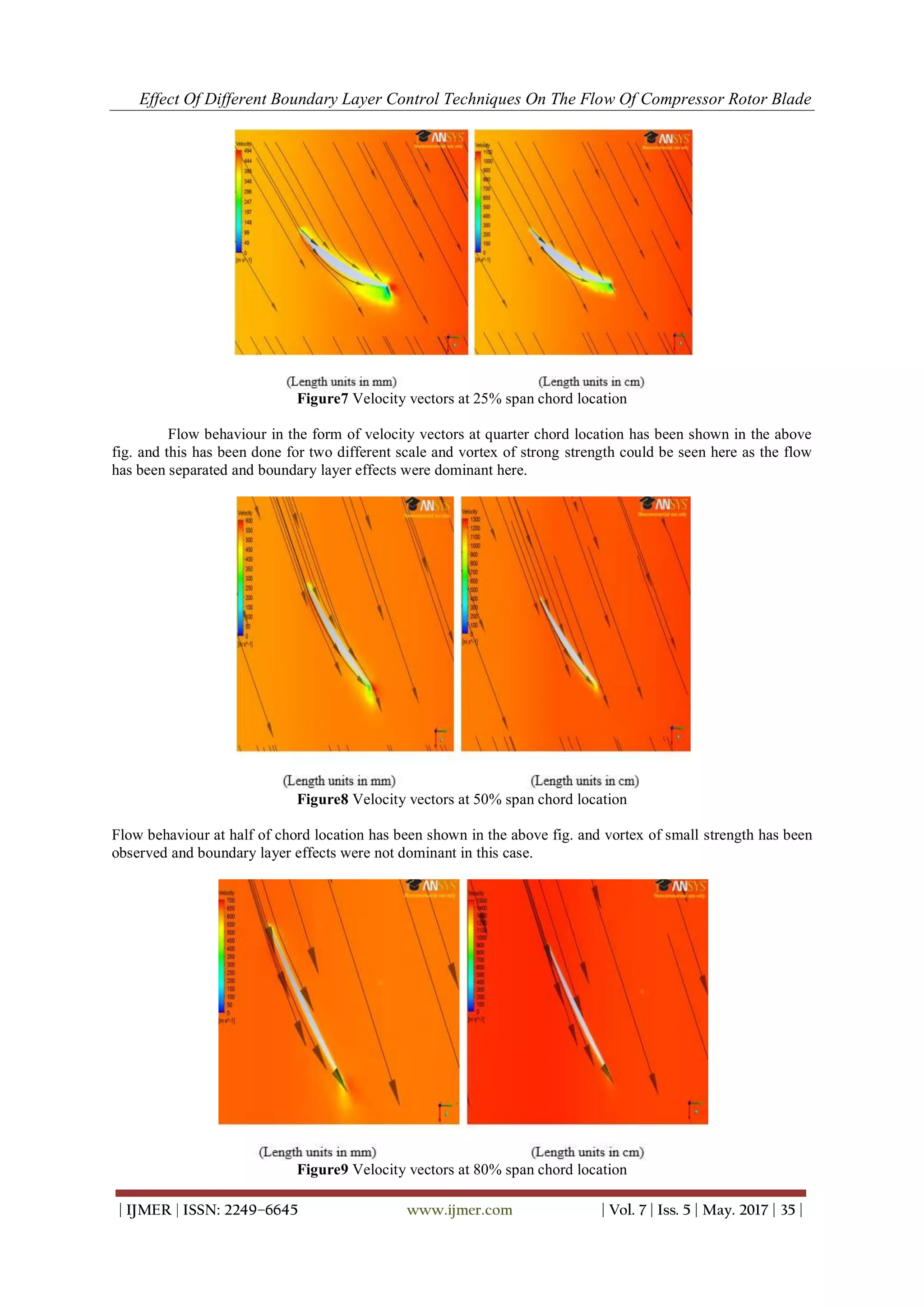
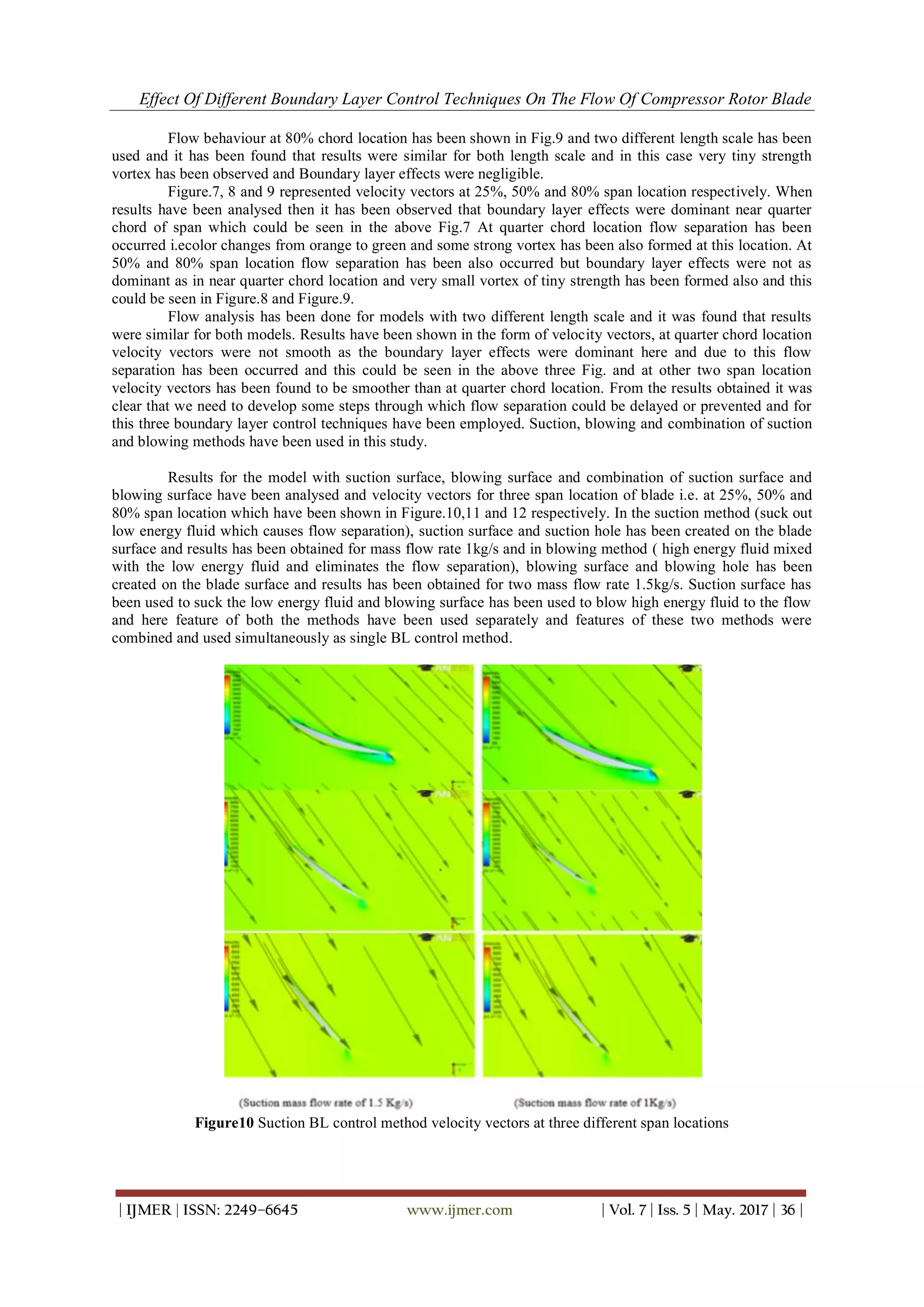
IV. RESULTS AND DISCUSSION
There were two defined models for analysis and this analysis has been done in CFX post-processor.
First model without any boundary layer control surfaces has been analysed and then model with combination of
suction and blowing boundary layer control surfaces. Three dimensional simulations have been done by using
simulation software ANSYS CFX. In post processing results have been analysed in the form of velocity vectors.
Velocity vectors have been checked not at various section of span but also at two models with changed length
units and rpm.
9. Effect Of Different Boundary Layer Control Techniques On The Flow Of Compressor Rotor Blade
| IJMER | ISSN: 2249–6645 www.ijmer.com | Vol. 7 | Iss. 5 | May. 2017 | 35 |
Figure7 Velocity vectors at 25% span chord location
Flow behaviour in the form of velocity vectors at quarter chord location has been shown in the above
fig. and this has been done for two different scale and vortex of strong strength could be seen here as the flow
has been separated and boundary layer effects were dominant here.
Figure8 Velocity vectors at 50% span chord location
Flow behaviour at half of chord location has been shown in the above fig. and vortex of small strength has been
observed and boundary layer effects were not dominant in this case.
Figure9 Velocity vectors at 80% span chord location
10. Effect Of Different Boundary Layer Control Techniques On The Flow Of Compressor Rotor Blade
| IJMER | ISSN: 2249–6645 www.ijmer.com | Vol. 7 | Iss. 5 | May. 2017 | 36 |
Flow behaviour at 80% chord location has been shown in Fig.9 and two different length scale has been
used and it has been found that results were similar for both length scale and in this case very tiny strength
vortex has been observed and Boundary layer effects were negligible.
Figure.7, 8 and 9 represented velocity vectors at 25%, 50% and 80% span location respectively. When
results have been analysed then it has been observed that boundary layer effects were dominant near quarter
chord of span which could be seen in the above Fig.7 At quarter chord location flow separation has been
occurred i.ecolor changes from orange to green and some strong vortex has been also formed at this location. At
50% and 80% span location flow separation has been also occurred but boundary layer effects were not as
dominant as in near quarter chord location and very small vortex of tiny strength has been formed also and this
could be seen in Figure.8 and Figure.9.
Flow analysis has been done for models with two different length scale and it was found that results
were similar for both models. Results have been shown in the form of velocity vectors, at quarter chord location
velocity vectors were not smooth as the boundary layer effects were dominant here and due to this flow
separation has been occurred and this could be seen in the above three Fig. and at other two span location
velocity vectors has been found to be smoother than at quarter chord location. From the results obtained it was
clear that we need to develop some steps through which flow separation could be delayed or prevented and for
this three boundary layer control techniques have been employed. Suction, blowing and combination of suction
and blowing methods have been used in this study.
Results for the model with suction surface, blowing surface and combination of suction surface and
blowing surface have been analysed and velocity vectors for three span location of blade i.e. at 25%, 50% and
80% span location which have been shown in Figure.10,11 and 12 respectively. In the suction method (suck out
low energy fluid which causes flow separation), suction surface and suction hole has been created on the blade
surface and results has been obtained for mass flow rate 1kg/s and in blowing method ( high energy fluid mixed
with the low energy fluid and eliminates the flow separation), blowing surface and blowing hole has been
created on the blade surface and results has been obtained for two mass flow rate 1.5kg/s. Suction surface has
been used to suck the low energy fluid and blowing surface has been used to blow high energy fluid to the flow
and here feature of both the methods have been used separately and features of these two methods were
combined and used simultaneously as single BL control method.
Figure10 Suction BL control method velocity vectors at three different span locations
11. Effect Of Different Boundary Layer Control Techniques On The Flow Of Compressor Rotor Blade
| IJMER | ISSN: 2249–6645 www.ijmer.com | Vol. 7 | Iss. 5 | May. 2017 | 37 |
Figure11 Blowing BL control method velocity vectors at three different span locations
Figure12 velocity vectors for model with combined suction and blowing control surfaces
Flow behaviour at the quarter chord location has been shown in first part of Figure.10, 11 and 12 and in
this case suction and blowing control surfaces has been introduced in the geometry and this could be observed
that boundary layer effects were not dominant and some vortex of small strength has been observed also. Flow
behaviour in the form of velocity vectors at half chord location with the introduction of suction and blowing
control surfaces have been shown in second part of above three Figures and velocity vectors were smooth and
very tiny vortex could be seen.Flow behaviour in the form of velocity vectors at 80% chord location with the
introduction of blowing and suction control surfaces has been shown in the last part of above three figures and
in this no vortex has been seen and flow separation has been prevented.
High energy fluid has been blown to the flow through blowing hole and suction surface used to suck
the low energy fluid through suction holes and in this study both the processes has been worked simultaneously
and fluid has been reenergized and there were no low energy fluid due to which flow separation occurred by this
way flow separation has been prevented. From the above figure it could be shown that by the use of boundary
layer control method velocity vectors found to be smoother and no strong vortex has been seen.
V. CONCLUSIONS
Results has been obtained for the both model i.e. model with and without boundary layer control
surfaces and it has been obtained that flow separation has been delayed or prevented with the introduction of
combination of suction and blowing surface in the blade geometry. When there was no boundary layer control
surface then flow separation occurred and boundary layer effects were dominant near quarter chord location due
to this some strong vortices has been formed but with the introduction of blowing and suction control surface in
the blade geometry flow separation has been prevented and vortex of very tiny strength has been observed. As a
12. Effect Of Different Boundary Layer Control Techniques On The Flow Of Compressor Rotor Blade
| IJMER | ISSN: 2249–6645 www.ijmer.com | Vol. 7 | Iss. 5 | May. 2017 | 38 |
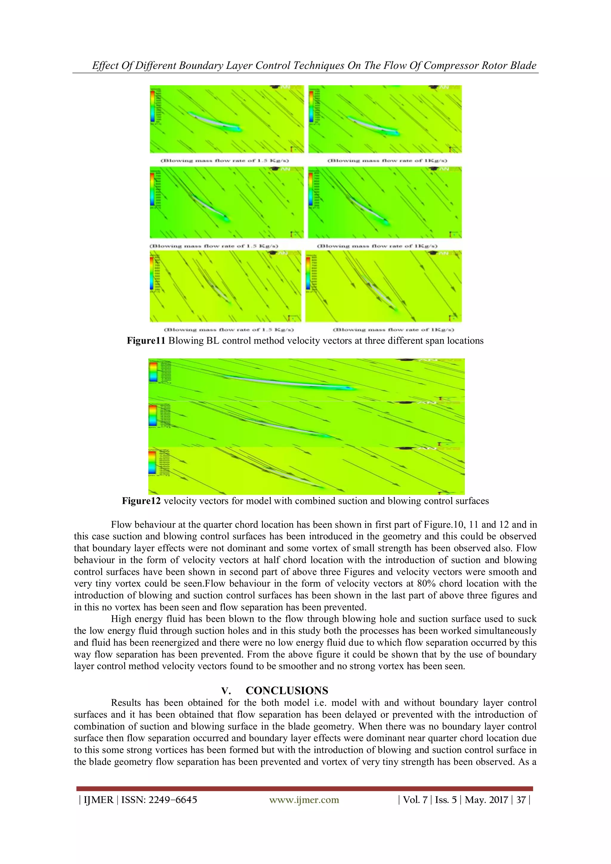
result pressure ratio has been observed as 1.652, 1.690 and 1.724and increment in pressure ratio has been found
to be 0.052, 0.09 and 0.11 for suction, blowing and combination of suction and blowing methods respectively.
ACKNOWLEDGEMENTS
Authors would like to thank university for providing computational facilities and colleagues for their
continuous support. Special thanks to co-author Late Twisha Patel for her support. I heartily pay my gratitude to
my colleagues Late Twisha Patel as she had been constantly helping me in it. Without their co-operation and
support, working on this paper would have been very difficult.
REFERENCES
[1]. Kumar Navneet, “Flow modification over rotor blade with suction boundary layer control technique”, International
Journal of Engineering Research and Application,Vol.6, no.6,pp 1-5, 2016.
[2]. Kumar N., “Modification of rotor blade flow with blowing boundary layer control technique”, International
Journal of Multidisciplinary Educational Research, vol.5, no.7, pp209-228, 2016.
[3]. Kumar Navneet and Patel Twisha, “Flow Modification over Rotor Blade with Boundary Layer Control
Technique”, International Journal of Innovative Research in Science, Engineering and Technology, vol.5, Issue8,
pp 15211-23, 2016.
[4]. Y. Ito, T. Watanabe and T. Himeno, “Effect of Endwall Countering on Flow Instability of Transonic Compressor”,
International Journal of Gas Turbine, Propulsion and Power system, Vol.2, no.1, 2008.
[5]. N. Ananthkrishnan, U. G. Vaidya and V. W. Walimbe, “Global stability and control analysis of axial compressor
stall and surge phenomena using bifurcation method”, Institution of mechanical Engineers J Power and Energy,
vol.217, no.1, 2001.
[6]. Abate, Giada,“Aerodynamic optimization of transonic axial compressor rotor”, Journal of Propulsion and Power,
vol.54, no.4, pp.41-55, 2003.
[7]. Benini and Ernesto,“Three dimensional multi objective design aerodynamic optimization of transonic compressor
rotor”,International Journal of Gas Turbine, Propulsion and Power System, vol.54, no.5, 2004.
[8]. Brian Joseph Schuler, “Experimental Investigation of an aspirated fan stage, doctoral diss.”, Massachusetts
Institute of Technology, Cambridge, MA, 2001.
[9]. A. Sarkar, B. Singla and N. Kumar, “CFD analysis of Rotor 67 Blades, University of Petroleum and Energy
Studies”, Dehradun, India pp.23-52, 2015.
[10]. Tangler, James L. The evolution of rotor and blade design.National Renewable Energy Laboratory, 2000.
[11]. Lachmann, Gustav Victor, ed. Boundary layer and flow control: its principles and application. Elsevier, 2014.
[12]. Reijnen, Duncan Peter. Experimental study of boundary layer suction in a transonic compressor.Diss.
Massachusetts Institute of Technology, 1997.
[13]. Tindell, Runyon H. "Blown boundary layer control system for a jet aircraft." U.S. Patent No. 5,447,283. 5 Sep.
1995.
[14]. Macaulay, Jack R., et al. "Aircraft boundary-layer control system." U.S. Patent No. 2,920,844. 12 Jan. 1960.