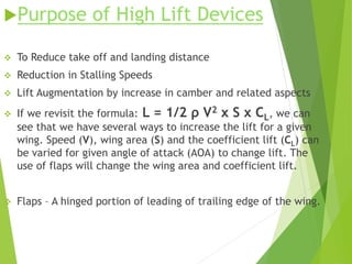
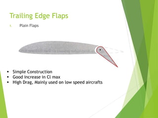
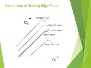
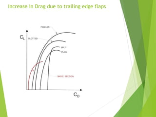
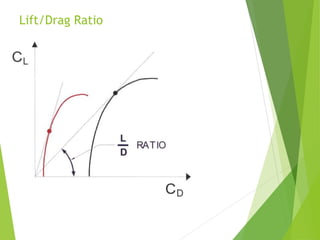
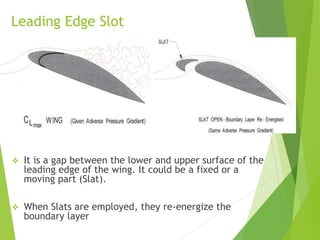
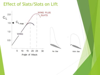
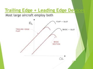
LIFT AUGMENTATION
DEVICES
BY:
SUHAIL AHMED
Contents of Presentation
1. Purpose of High Lift Devices
2. Flaps
Trailing Edge Flaps
- Plain Flaps
- Split Flaps
- Slotted and Multiple Slotted Flaps
- Fowler Flaps
- Comparison of Trailing Edge flaps
- Cl max and stalling angles
- Drag, Lift/Drag Ratio
- Pitching and centre of pressure moment
- Change of Downwash
- Overall Pitch change
Contents of Presentation
Leading Edge High Lift Devices
- Leading Edge Flaps
- Kruger Flaps
- Variable Camber Leading Edge Flaps
- Effects of Leading Edge Flaps on Lift
- Leading Edge Slots/Slats
- Automatic Slots
- Disadvantages of Slots
- Drag and Pitching moment
Trailing + Leading Edge Devices together
Purpose of High Lift Devices
 To Reduce take off and landing distance
 Reduction in Stalling Speeds
 Lift Augmentation by increase in camber and related aspects
 If we revisit the formula: L = 1/2 ρ V2 x S x CL, we can
see that we have several ways to increase the lift for a given
wing. Speed (V), wing area (S) and the coefficient lift (CL) can
be varied for given angle of attack (AOA) to change lift. The
use of flaps will change the wing area and coefficient lift.
 Flaps – A hinged portion of leading of trailing edge of the wing.
Trailing Edge Flaps
1. Plain Flaps
 Simple Construction
 Good increase in Cl max
 High Drag, Mainly used on low speed aircrafts
Cl max and Stalling Angle
Effective angle of attack increases with
extension of trailing edge flaps
2. Split Flaps
• The flaps are part of lower surface of trailing edge.
• The upper surface contour being un affected when flap is lowered
• or deployed.
• The split flaps give some more increase in lift as compare to plain flaps at
• low angle of attack .
 Split flaps gives slightly more lift at high angle of attack as upper camber
is not increased and separation is delayed.
3. Slotted and Multiple Slotted Flaps
• A Slotted flaps have a gap or slot in them to allow faster-moving air
from the lower surface to flow over the upper surface.
• Re-energies the boundary layer. And it delays the separation of
airflow on upper surface.
• Slotted flaps gives a bigger increase in Clmax than plain or split
flap and much less drag
• Slotted flaps have more complex construction.
4. Fowler Flaps
Fowler Flaps(Contd.)
 combined effect of increase in camber and
surface area
 the fowler flaps give the greatest increase in lift.
 It gives least drag because of the slots and
reduction in thickness: Chord ratio.
 However, the change in pitching moment is
greatest.
Comparison of Trailing Edge Flaps
Aerodynamic effects of flaps
 Increase in Drag due to trailing edge flaps
 Lift/Drag Ratio
 Pitching Moment
 Centre of Pressure Movement.
 Change of Downwash
Increase in Drag due to trailing edge flaps
Lift/Drag Ratio
LIFT/DRAG RATIO
 This ratio (L/D) is also reduced when full
flaps are extended. Normally, flap
settings between 0 - 25° will noticeably
increase lift more than drag, ideal for
take off. Flap settings beyond 25° will
increase drag much more than lift, ideal
for landing and steep approaches to
runways when there are obstacles in the
approach path.
Pitching Moment
Centre of Pressure Movement.
 Flaps extension will cause the CP to move aft
thus pitching the aircraft nose down.
 Flaps retraction will move the CP forward thus
pitching the aircraft nose up.
Change of Downwash
Tail plane effective angle of attach is
determined by the downwash of the wing.
Lowering flaps increases downwash thus
decreasing tail plane angle of attack. This
has a nose up pitching moment.
Leading Edge High Lift Devices
Two types:
Leading Edge Flaps
Leading Edge Slats and Slots
Leading Edge Flaps
(They Increase the camber of the leading edge)
Kruger Flaps
They are fitted at lower surface of wing leading
edge, rotated about their forward edge as shown in
the fig.
Variable camber leading edge flap
 They give better efficiency than Kruger Flaps by giving
better leading edge profile.
Effect of Leading edge Flaps on Lift
Leading Edge Slot
 It is a gap between the lower and upper surface of the
leading edge of the wing. It could be a fixed or a
moving part (Slat).
 When Slats are employed, they re-energize the
boundary layer
Effect of Slats/Slots on Lift
Automatic Slats
On some aircrafts slots are not controlled by the
pilot, but operate automatically their movement
depends on change in pressure occur around the
leading edge at low angle of attack the pressure
around the stagnation point keep the slat in
closed position. At high angle of attacks the
stagnation point moves underneath the leading
edge and suction pressure occur on the upper
surface of slat this pressure cause slat to move
forward and create the slot
Disadvantages of a Slat/Slot
 Much higher angle of attack is required to benefit from
the increased Cl max by the use of slat/slot. Visibility
could hamper by increased nose up pitch and landing
could be difficult.
Drag and Pitching Moment
 Compare to trailing edge devices, the drag and
pitching moment is small.
Trailing Edge + Leading Edge Devices
Most large aircraft employ both
THANK
YOU

Lift Augmentation Devices Or High Lift Devices

  • 1.
  • 3.
    Contents of Presentation 1.Purpose of High Lift Devices 2. Flaps Trailing Edge Flaps - Plain Flaps - Split Flaps - Slotted and Multiple Slotted Flaps - Fowler Flaps - Comparison of Trailing Edge flaps - Cl max and stalling angles - Drag, Lift/Drag Ratio - Pitching and centre of pressure moment - Change of Downwash - Overall Pitch change
  • 4.
    Contents of Presentation LeadingEdge High Lift Devices - Leading Edge Flaps - Kruger Flaps - Variable Camber Leading Edge Flaps - Effects of Leading Edge Flaps on Lift - Leading Edge Slots/Slats - Automatic Slots - Disadvantages of Slots - Drag and Pitching moment Trailing + Leading Edge Devices together
  • 5.
    Purpose of HighLift Devices  To Reduce take off and landing distance  Reduction in Stalling Speeds  Lift Augmentation by increase in camber and related aspects  If we revisit the formula: L = 1/2 ρ V2 x S x CL, we can see that we have several ways to increase the lift for a given wing. Speed (V), wing area (S) and the coefficient lift (CL) can be varied for given angle of attack (AOA) to change lift. The use of flaps will change the wing area and coefficient lift.  Flaps – A hinged portion of leading of trailing edge of the wing.
  • 6.
    Trailing Edge Flaps 1.Plain Flaps  Simple Construction  Good increase in Cl max  High Drag, Mainly used on low speed aircrafts
  • 7.
    Cl max andStalling Angle Effective angle of attack increases with extension of trailing edge flaps
  • 8.
    2. Split Flaps •The flaps are part of lower surface of trailing edge. • The upper surface contour being un affected when flap is lowered • or deployed. • The split flaps give some more increase in lift as compare to plain flaps at • low angle of attack .  Split flaps gives slightly more lift at high angle of attack as upper camber is not increased and separation is delayed.
  • 9.
    3. Slotted andMultiple Slotted Flaps • A Slotted flaps have a gap or slot in them to allow faster-moving air from the lower surface to flow over the upper surface. • Re-energies the boundary layer. And it delays the separation of airflow on upper surface. • Slotted flaps gives a bigger increase in Clmax than plain or split flap and much less drag • Slotted flaps have more complex construction.
  • 10.
  • 11.
    Fowler Flaps(Contd.)  combinedeffect of increase in camber and surface area  the fowler flaps give the greatest increase in lift.  It gives least drag because of the slots and reduction in thickness: Chord ratio.  However, the change in pitching moment is greatest.
  • 12.
  • 13.
    Aerodynamic effects offlaps  Increase in Drag due to trailing edge flaps  Lift/Drag Ratio  Pitching Moment  Centre of Pressure Movement.  Change of Downwash
  • 14.
    Increase in Dragdue to trailing edge flaps
  • 15.
  • 16.
    LIFT/DRAG RATIO  Thisratio (L/D) is also reduced when full flaps are extended. Normally, flap settings between 0 - 25° will noticeably increase lift more than drag, ideal for take off. Flap settings beyond 25° will increase drag much more than lift, ideal for landing and steep approaches to runways when there are obstacles in the approach path.
  • 17.
    Pitching Moment Centre ofPressure Movement.  Flaps extension will cause the CP to move aft thus pitching the aircraft nose down.  Flaps retraction will move the CP forward thus pitching the aircraft nose up.
  • 18.
    Change of Downwash Tailplane effective angle of attach is determined by the downwash of the wing. Lowering flaps increases downwash thus decreasing tail plane angle of attack. This has a nose up pitching moment.
  • 20.
    Leading Edge HighLift Devices Two types: Leading Edge Flaps Leading Edge Slats and Slots
  • 21.
    Leading Edge Flaps (TheyIncrease the camber of the leading edge) Kruger Flaps They are fitted at lower surface of wing leading edge, rotated about their forward edge as shown in the fig.
  • 22.
    Variable camber leadingedge flap  They give better efficiency than Kruger Flaps by giving better leading edge profile.
  • 23.
    Effect of Leadingedge Flaps on Lift
  • 24.
    Leading Edge Slot It is a gap between the lower and upper surface of the leading edge of the wing. It could be a fixed or a moving part (Slat).  When Slats are employed, they re-energize the boundary layer
  • 25.
  • 26.
    Automatic Slats On someaircrafts slots are not controlled by the pilot, but operate automatically their movement depends on change in pressure occur around the leading edge at low angle of attack the pressure around the stagnation point keep the slat in closed position. At high angle of attacks the stagnation point moves underneath the leading edge and suction pressure occur on the upper surface of slat this pressure cause slat to move forward and create the slot
  • 27.
    Disadvantages of aSlat/Slot  Much higher angle of attack is required to benefit from the increased Cl max by the use of slat/slot. Visibility could hamper by increased nose up pitch and landing could be difficult. Drag and Pitching Moment  Compare to trailing edge devices, the drag and pitching moment is small.
  • 28.
    Trailing Edge +Leading Edge Devices Most large aircraft employ both
  • 29.