Downloaded 51 times
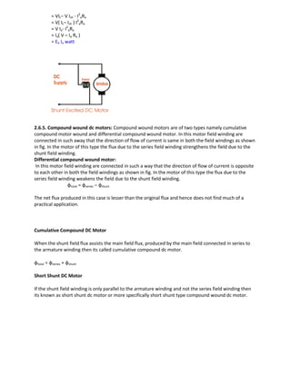
![Back e.m.f developed, Eb = V – I Ra
Powerdrawnfromthemains,
P=VIMechanicalpowerdeveloped,
Pm=Powerinputtoarmature-
powerlostinarmature=VI–I2
Ra=I(V–IRa)=EbI watt
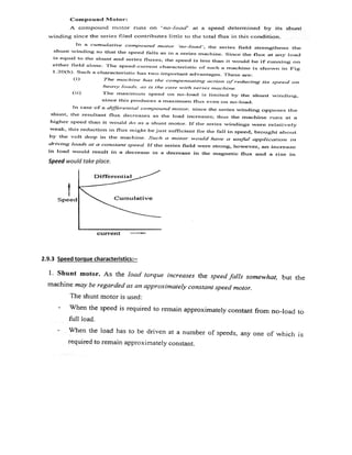
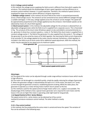
2.6. 3. Series wound dc motors:
As the name implies, the field coils, consisting of a few turns of thick wires, are connected in series with
the armature as shown in the fig. The cross-sectional of the wire for the coils has to be fairly to carry the
armature current, but owing to large current, the number of turns of wire in them need not be large.
In a dc series motor,Armature current, Ia = series field current, Ise= Line current,
IL= I (say)
Armature current,Ia = series field current, Ise = Linecurrent, IL= I (say)
Back emf developed,
Eb = V – I (Ra + Rse )
Power drawn from the mains, P = VI
Mechanical power developed,
Pm = Power input to armature- power lost in armature= VI – I2
(Ra + Rse)
= I [V – I (Ra + Rse) ]
= Eb I watts
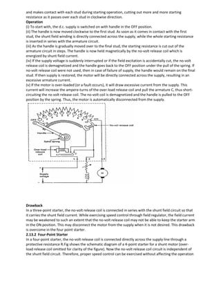
2.6.4. Shunt wound dc motors:
The word “ shunt ’’ means “ parallel ’’ . In these motors , the field coils are connected in parallel with the
armature. The field winding consists of a large number of turns of thin wire so as to provide large
resistance. The field current is much less than the armature current, sometimes as low as 5%.
The current supplied to the motor is divided into two paths, one from the field winding and second
through the armature i.e.Input line current,
IL =Ia + Ish
Where Ia is the armature current and Ish is the shunt field current and is given by where V is the supply
voltage, Rsh is the shunt field resistance
Ish = V/Rsh
Back emf developed, Eb = V – I Ra Power drawn from the mains,
P = VIL
Mechanical power developed,
Pm = Power input to armature- power lost in armature](https://image.slidesharecdn.com/lecturenotes-2-151212072143/85/Lecture-notes-2-Electrical-machine-1-3-320.jpg)
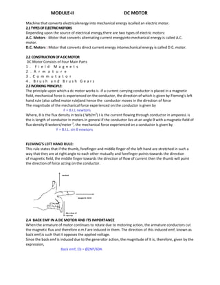
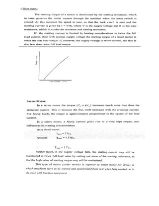
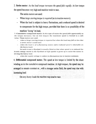
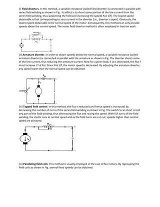
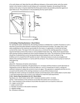
![Long Shunt DC Motor
If the shunt field winding is parallel to both the armature winding and the series field winding then it’s
known as long shunt type compounded wound dc motor or simply long shunt dc motor.
Short shunt and long shunt type motors have been shown in the diagram below.
2.7 Performance calculations
In most applications, DC motors are used for driving mechanical loads. Some applications require that
the speed remain constant as the load on the motor changes. In some applications the speed is required
to be
Controlled over a wide range. It is therefore important to study the relationship between torque and
speed of the motor.
2.8 Speed Regulation
The performance measure of interest is the speed regulation, defined as the change in speed as full load
is
applied to the motor. It can be expressed as:
%Speed regulation= [ (N no load – N full load ) /N full load ] X 10
2.9DC MOTOR CHARACTERISTICS:-
Torque-current characteristics.
Torque- speed characteristics.
Speed- current characteristics.
2.9.1 Torque-current characteristics:-](https://image.slidesharecdn.com/lecturenotes-2-151212072143/85/Lecture-notes-2-Electrical-machine-1-5-320.jpg)
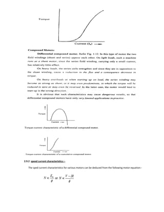
![Then, the ‘hot’ resistance, allowing a temperature rise of 50Co is found thus:
R15 = Ro (1 + 15α0) ; R65 =Ro (1 + 65α0),
R65= R15 X [(1+65αo)/(1+15αo)]
If we subtract from the total input the no-load armature Cu loss, then we get constant losses.
Constant losses Wc= VI0−(I0−Ish)2Ra
Knowing the constant losses of the machine, its efficiency at any other load can be determined as given
below. Let I = load current at which efficiency is required. Then, armature current is
Ia= I − Ish ...if machine is motoring
= I + Ish ...if machine is generating
Efficiency when running as a motor
Input = VI,
Armature Cu loss = Ia
2
Ra=(I-Ish)2
Ra
Constant losses = Wc
Total losses = (I−Ish)2
Ra+Wc
Efficiency = (input-losses)/ Input
Efficiency when running as a generator
Output = VI ; Armature Cu loss = (I + Ish)2
Ra; constant loss=Wc
Total losses = (I+Ish)2
R+Wc
Efficiency = (output)/(output + losses)
Main Disadvantages
1. No account is taken of the change in iron losses from no-load to fullload. At full-load, due to armature
reaction, flux is distorted which increases the iron losses in some cases by as much as 50%.
2. As the test is on no-load, it is impossible to know whether commutation would be satisfactory at full-
load and whether the temperature rise would be within the specified limits.
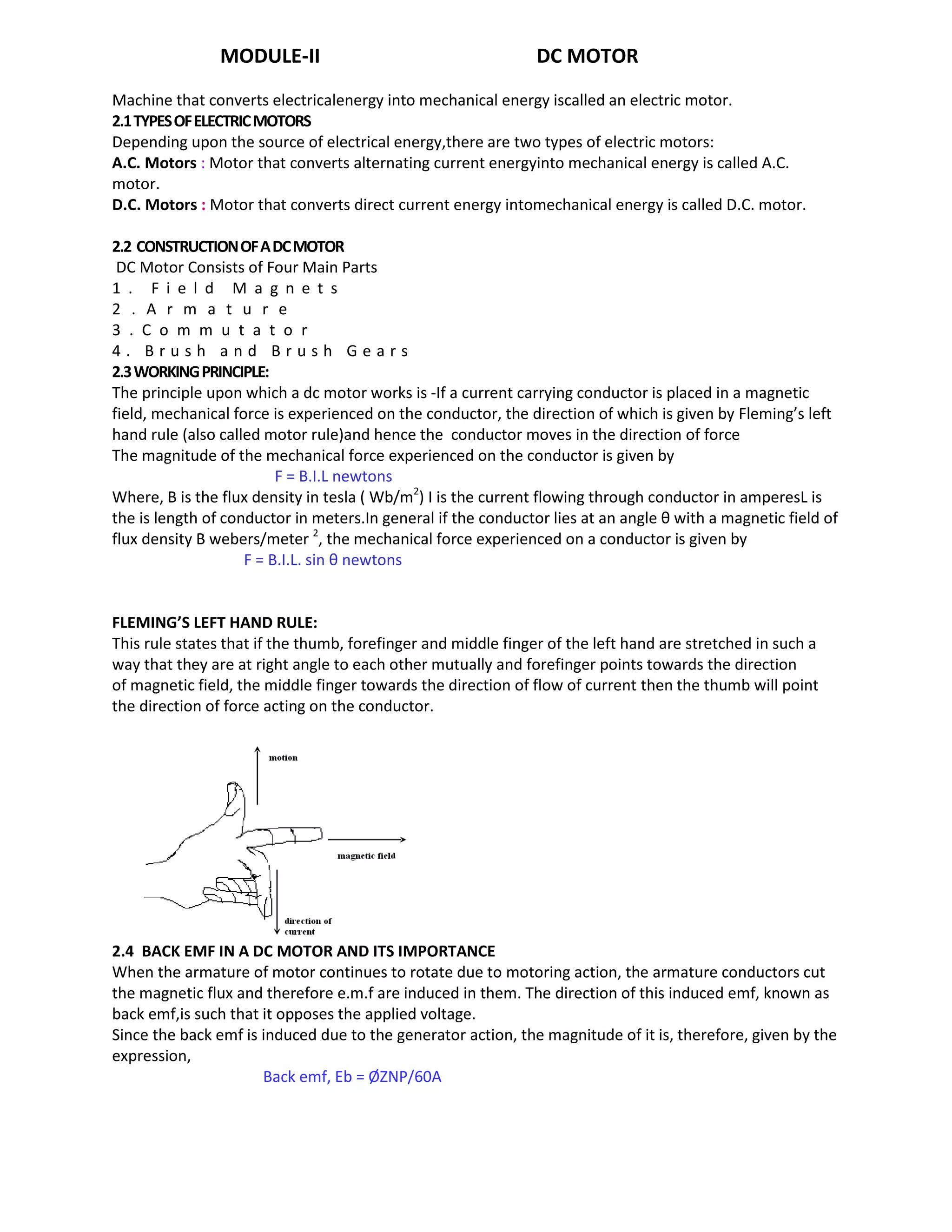
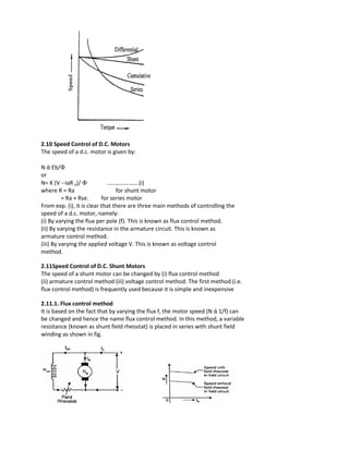
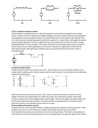
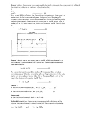
2.15.2. Regenerative or Hopkinson's Test (Back to Back Test):
By this method, full-load test can be carried out on two shunt machines, preferably identical ones,
without wasting their outputs. The two machines are mechanically coupled and are so adjusted
electrically that one of them runs as a motor and the other as a generator. The mechanical output of the
motor drives the generator and the electrical output of generator is used in supplying the greater part of
input to the motor. If there were no losses in the machines, they would have run without any external
power supply. But due to these losses, generator output is not sufficient to drive the motor and vice-
versa. The losses are supplied either by an extra motor which is belt-connected to the motor-generator
set, or by electrically from the supply mains. The two shunt machines are connected in parallel. They
are, to begin with, started as unloaded motors. Then, the field of one is weakened and that of the other
is strengthened so that the former runs as a motor and the latter as a generator. The usual method of
procedure is as follows: Machine M is started up from the supply mains with the help of a starter (not
shown) whereas main switch S of the other machine is kept open. Its speed is adjusted to normal value
by means of its field regulator. Machine M drives machine G as a generator and its voltage is read on
voltmeter V. The voltage of G is adjusted by its field regulator until voltmeter V1 reads zero, thereby
showing that its voltage is the same, both in polarity and magnitude as that of the main supply.
Thereafter, S is closed to parallel the machines. By adjusting the respective field regulators, any load can
now be thrown on to the machines. Generator current I1 can be adjusted to any desired value by
increasing the excitation of G or by reducing the excitation of M and the corresponding values of
different ammeters are read. The electrical output of the generator plus the small power taken from the
supply, is taken by the motor and is given out as a mechanical power after supplying the motor losses. If
supply voltage is V, then
Motor input=V(I1+I2), where I2 is the current taken from the supply. Generator output = VI1](https://image.slidesharecdn.com/lecturenotes-2-151212072143/85/Lecture-notes-2-Electrical-machine-1-21-320.jpg)
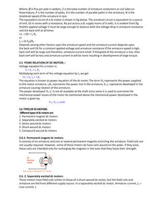
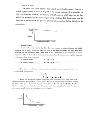
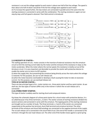
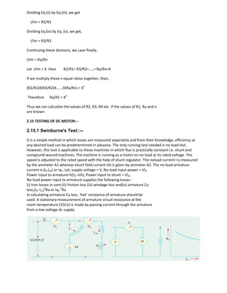
![Assuming that both machines have the same efficiency η.
Output of motor = η × input = η V(I1+I2) = generator input
Output of generator=η×input=η×ηV(I1+I2)=η2V(I1 + I2)
η2V(I1 + I2)=VI1 or η=√
Let Ra= armature resistance of each machine
I3= exciting current of the generator
I4= exciting current of the motor
Armature Cu loss in generator = (I1+I3)2
Ra
Armature Cu loss in motor = (I1+I2-I4)2
Ra
Shunt Cu loss in generator = VI3
Shunt Cu loss in motor = VI4
But total motor and generator losses are equal to the power supplied by the mains. Power drawn from
supply = VI2If we subtract the armature and shunt Cu losses from this, we get the stray losses of both
machines.
Total stray losses for the set= VI2−[(I1+I3)2
Ra+(I1+I2−I4)2
Ra+VI3+VI4]=W
Making one assumption that stray losses are equally divided between the two machines, we have Stray
loss per machine = W/2
For Generator Total losses = (I1+I3)2
Ra+VI3+W/2=Wg
Output=VI1 ηg=VI1 /(VI1+Wg)
For Motor
Total losses = (I1+I2-I4)2
Ra+VI4+W/2=Wm
Input = V(I1+I2) ηm= [V(I1+I2)- Wm ] / V(I1+I2)](https://image.slidesharecdn.com/lecturenotes-2-151212072143/85/Lecture-notes-2-Electrical-machine-1-22-320.jpg)

1. A DC motor converts direct current electrical energy into mechanical energy through electromagnetic induction. It consists of field magnets, an armature, a commutator, and brushes. 2. The motor's working principle is that a current-carrying conductor in a magnetic field experiences a mechanical force based on Fleming's left-hand rule. Back EMF is induced in the armature as it rotates, opposing the applied voltage. 3. A DC motor's speed can be controlled through various methods like adjusting the field flux, armature resistance, or applied voltage. The speed-torque characteristics differ between series, shunt, and compound wound DC motor types.