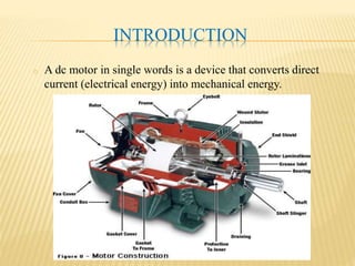
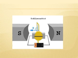
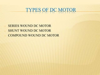
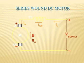
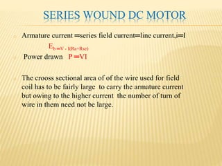
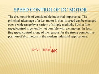
This document provides an overview of DC motors, including their basic working principles, types (shunt, series, compound), characteristics such as torque-current and speed-current relationships, and components like armature and field windings. It describes how DC motors function by converting electrical energy from a power source into mechanical rotation of an armature, and how speed can be controlled through varying the current. Losses within the motor such as copper and iron losses are also discussed.
DC motors
Torque & Speed Equations
Torque -Armature current Characteristics
Speed - Armature current Characteristics
Torque-speed characteristics
Applications
Speed Control
DC motors
Torque & Speed Equations
Torque -Armature current Characteristics
Speed - Armature current Characteristics
Torque-speed characteristics
Applications
Speed Control
It is based on current transformer description
It's working and applications are present in it ,it also includes videos of it's windings and it's inrush ability of transformer, and also about instrument transformer and it's working with applications.Current transformers are used-in measuring high currents and connected with it in parallel to it
EMF EQUATION OF DC GENERATOR,DC MOTOR|DAY15|BACK EMF,TORQUE OF DC MOTOR|BASIC...Prasant Kumar
#EMF EQUATION OF DC GENERATOR
#EMF EQUATION OF DC MOTOR
#TORQUE EQUATION OF DC MOTOR
# EMF EQUATION OF DC MOTOR IN HINDI
#DERIVATION OF DC MOTOR EMF EQUATION
#FARADAY LAW OF ELECTROMAGNETIC INDUCTION
#back emf in dc motor
#back emf in dc motor in hindi
In this video you will learn about,derivation of dc machine emf equation,back emf,torque equation of dc motor,dc generated,dc motor.To understand electrical machine with trick watch all videos,
MUST UPGRADE YOUR KNOWLEDGE BY FLIPPED LEARNING
#Topic - ELECTRICAL TRANSFORMER
~ Link of all sessions are.
DAY 1 (Need/Definition)
https://youtu.be/BvaykFJ_NoE
DAY 2 (Working principle and Construction)
https://youtu.be/06rgxocihaM
DAY 3 (EMF equation and Turns Ratio)
https://youtu.be/g7e5xBPmv3Y
DAY 4 (Classification of Transformer)
https://youtu.be/6NP5L4MlvY4
DAY 5 ( Ideal and practical transformer on no load)
(Equivalent Transformer)
https://youtu.be/6LCLQC1p3lg
DAY 6 ( Losses in Transformer)
https://youtu.be/ObYNiGgd3hA
DAY 7 (O.C. and S.C. test)
https://youtu.be/8WiJRawHiTce/6LCLQC1p3lg
DAY 8 (Voltage Regulation & Efficiency)
https://youtu.be/6LCLQC1p3lg
DAY 9 (Zero Lecture)
https://youtu.be/N4xWOwgi8I4
DAY 10 (Classification of machine)
https://youtu.be/bmxnU5rC5m4
Construction of Machine
https://youtu.be/34mpphDk3gg
Working Principle of Synchronous Generator & Synchronous Motor
https://youtu.be/bkgf72M8BCY
Working Principle of Induction Motor
https://youtu.be/Lj_iQBoRiK0
Faradays laws, Lenz law, Fleming's Right hand and Left hand rule, principle and working of DC Generator and motor, back EMF, types of DC motor, Torque equation of dc motor, characteristics of DC shunt and Series motors, speed control of DC Shunt motor, industrial applications of DC Shunt and DC series motor.
Advantages and Disadvatages of AC/DC MotorFika Khamis
Simple explanation on advantages and disadvantages of AC and DC motor. Focusing on main point only since the slides is for presentation. Originally design by me.
CFD Simulation of By-pass Flow in a HRSG module by R&R Consult.pptxR&R Consult
CFD analysis is incredibly effective at solving mysteries and improving the performance of complex systems!
Here's a great example: At a large natural gas-fired power plant, where they use waste heat to generate steam and energy, they were puzzled that their boiler wasn't producing as much steam as expected.
R&R and Tetra Engineering Group Inc. were asked to solve the issue with reduced steam production.
An inspection had shown that a significant amount of hot flue gas was bypassing the boiler tubes, where the heat was supposed to be transferred.
R&R Consult conducted a CFD analysis, which revealed that 6.3% of the flue gas was bypassing the boiler tubes without transferring heat. The analysis also showed that the flue gas was instead being directed along the sides of the boiler and between the modules that were supposed to capture the heat. This was the cause of the reduced performance.
Based on our results, Tetra Engineering installed covering plates to reduce the bypass flow. This improved the boiler's performance and increased electricity production.
It is always satisfying when we can help solve complex challenges like this. Do your systems also need a check-up or optimization? Give us a call!
Work done in cooperation with James Malloy and David Moelling from Tetra Engineering.
More examples of our work https://www.r-r-consult.dk/en/cases-en/
Saudi Arabia stands as a titan in the global energy landscape, renowned for its abundant oil and gas resources. It's the largest exporter of petroleum and holds some of the world's most significant reserves. Let's delve into the top 10 oil and gas projects shaping Saudi Arabia's energy future in 2024.
Cosmetic shop management system project report.pdfKamal Acharya
Buying new cosmetic products is difficult. It can even be scary for those who have sensitive skin and are prone to skin trouble. The information needed to alleviate this problem is on the back of each product, but it's thought to interpret those ingredient lists unless you have a background in chemistry.
Instead of buying and hoping for the best, we can use data science to help us predict which products may be good fits for us. It includes various function programs to do the above mentioned tasks.
Data file handling has been effectively used in the program.
The automated cosmetic shop management system should deal with the automation of general workflow and administration process of the shop. The main processes of the system focus on customer's request where the system is able to search the most appropriate products and deliver it to the customers. It should help the employees to quickly identify the list of cosmetic product that have reached the minimum quantity and also keep a track of expired date for each cosmetic product. It should help the employees to find the rack number in which the product is placed.It is also Faster and more efficient way.
Hybrid optimization of pumped hydro system and solar- Engr. Abdul-Azeez.pdffxintegritypublishin
Advancements in technology unveil a myriad of electrical and electronic breakthroughs geared towards efficiently harnessing limited resources to meet human energy demands. The optimization of hybrid solar PV panels and pumped hydro energy supply systems plays a pivotal role in utilizing natural resources effectively. This initiative not only benefits humanity but also fosters environmental sustainability. The study investigated the design optimization of these hybrid systems, focusing on understanding solar radiation patterns, identifying geographical influences on solar radiation, formulating a mathematical model for system optimization, and determining the optimal configuration of PV panels and pumped hydro storage. Through a comparative analysis approach and eight weeks of data collection, the study addressed key research questions related to solar radiation patterns and optimal system design. The findings highlighted regions with heightened solar radiation levels, showcasing substantial potential for power generation and emphasizing the system's efficiency. Optimizing system design significantly boosted power generation, promoted renewable energy utilization, and enhanced energy storage capacity. The study underscored the benefits of optimizing hybrid solar PV panels and pumped hydro energy supply systems for sustainable energy usage. Optimizing the design of solar PV panels and pumped hydro energy supply systems as examined across diverse climatic conditions in a developing country, not only enhances power generation but also improves the integration of renewable energy sources and boosts energy storage capacities, particularly beneficial for less economically prosperous regions. Additionally, the study provides valuable insights for advancing energy research in economically viable areas. Recommendations included conducting site-specific assessments, utilizing advanced modeling tools, implementing regular maintenance protocols, and enhancing communication among system components.
Student information management system project report ii.pdfKamal Acharya
Our project explains about the student management. This project mainly explains the various actions related to student details. This project shows some ease in adding, editing and deleting the student details. It also provides a less time consuming process for viewing, adding, editing and deleting the marks of the students.
2. CONTENTS
INTRODUCTION
WORKING PRINCIPLE OF DC MOTOR
BACK EMF DC MOTOR
TYPES OF DC MOTOR
TORQUE OF DC MOTOR
ARMATURE REACTION OF DC MOTOR
INTERPOLES OF DC MOTOR
CHARATERISTICS OF DC MOTOR SHUNT, SERIES AND
COMPOUND
SPEED CONTROL OF DC MOTOR
LOSSES IN DC MOTOR
EFFICIENCY OF DC MOTOR
3. INTRODUCTION
o A dc motor in single words is a device that converts direct
current (electrical energy) into mechanical energy.
4. WORKING PRINCIPLE OF DC MOTOR
o Step 1:
Initially considering the armature is in its starting point or
reference position where the angle α = 0.
o ∴ τ = BIL w cos0 = BILw
Since α = 0, the term cos α = 1, or the maximum value, hence
torque at this position is maximum given by τ = BILw. This high
starting torque helps in overcoming the initial inertia of rest of the
armature and sets it into rotation.
5.
6. o Step 2:
o Once the armature is set in motion, the angle α between the actual
position of the armature and its reference initial position goes on
increasing in the path of its rotation until it becomes 90° from its
initial position. Consequently the term cosα decreases and also the
value of torque.
The torque in this case is given by τ = BILwcosα which is less than
BIL w when α is greater than 0°.
7.
8. o Step 3:
o In the path of the rotation of the armature a point is reached where
the actual position of the rotor is exactly perpendicular to its
initial position, i.e. α = 90°, and as a result the term cosα = 0.
The torque acting on the conductor at this position is given by.
τ = BILwcos90° = 0
9.
10. BACK EMF OF DC MOTOR
o When the motor Armature continue to rotate due to motor action
the Armature conductor cut the magnetic flux emf is induced in
them is known as back emf .
o It Denoted by Eb
Eb ═ ΦZNP/60A
11. TYPES OF DC MOTOR
o SERIES WOUND DC MOTOR
o SHUNT WOUND DC MOTOR
o COMPOUND WOUND DC MOTOR
12. SERIES WOUND DC MOTOR
A
E
Ra
IL
V
+
_
Ia
AA
ISE
YY
+
_
M SUPPLY
13. SERIES WOUND DC MOTOR
o Armature current ═series field current═line current,i═I
Eb ═V - I(Ra+Rse)
o Power drawn P ═VI
o The crooss sectional area of of the wire used for field
coil has to be fairly large to carry the armature current
but owing to the higher current the number of turn of
wire in them need not be large.
14. SHUNT WOUND DC MOTOR
SUPPLYE
Ra
IL
V
FF
If
Ia
AA
+
_
F
M
A
15. SHUNT WOUND DC MOTOR
o In this type of excitation , armature and field windings are
connected across a constant source of supply.
o The field current If is drawn from the same source as that of
armature current.
16. COMPOUND WOUND DC MOTOR
o Compoud wound:- which has two field windings; one
connected inparallel with the armature and the other in series with
it.
A
E
Ra
IL
V
Ia
AA
ISE
YYY +
_
ISh
Z
ZZ
Rsh
SUPPLY
M
17. o There are two types of compound dc motor connections :-
(1) Short shunt connection :-When the shunt field winding is directly
connected across the armature terminals it is called short-shunt connection.
(2) Long shunt connectin :-When the shunt winding is
connected that it shunts the series combination of armature
and series field. it is called long-shunt connection.
18.
19. TORQUE OF DC MOTOR
o Whenever armature carries current in
presence of flux, conductor
experiences force which gives rise to
the electromagnetic torque. In this
section we shall derive an expression
for the electromagnetic torque Te
developed in a d.c machine.
Obviously Te will be developed both
in motor and generator mode of
operation. It may be noted that the
direction of conductor currents
reverses as we move from one pole to
the other. This ensures unidirectional
torque to be produced. The derivation
of the torque expression is shown
below.
20. TORQUE OF DC MOTOR
Let, Ia = Armature current
Average flux density Bav = pφ/πDL
Then, Ia/a = Current flowing through each conductor.
Force on a single conductor = BavLIa/a
Torque on a single conductor = BavLDIa/2a
Total electromagnetic torque developed, Te =
zBavIaLD/2a
Putting the value of Bav,
we get Te = pz φIa/2πa
21. ARMATURE REACTION OF DC MOTOR
(a) Armature reaction is the
magnetic field produced by the
armature current.
(b)Armature reaction aids the main
flux in one half of thepole and
opposes the main flux in the
other half of the pole .
(c)However due to saturation of the
pole
faces the net effect of Armature
reaction is demagnetizing.
23. INTERPOLES OF DC MOTOR
o These are fixed to the yoke in between the main poles of a dc
motor. These are usually tapered with sufficient sectional area at
the root to avoit megnetic saturation. The interpoles winding,
consisting of a few turn of thik wire, is connected in series with
the armature so that its magnetomotive force is proportional to
armature current.
o The effect of armature reaction in the armature zone can be
overcome by interpole placed in between the main pole. The
megnetic axis of interpole winding is the line with the quadrature
axis. Interpole winding is connected in series with armature so the
interpole mmf is able to neutralize the effect of armature mmf in
the interpolar zone at are level of load current not exceeding the
safe limit.
24. CHARACTERISTICS OF DC MOTOR
o There are three principal types of d.c. motors viz., shunt motors,
series motorsand compound motors. Both shunt and series types
have only one field windingwound on the core of each pole of the
motor. The compound type has twoseparate field windings wound
on the core of each pole. The performance of ad.c. motor can be
judged from its characteristic curves known as
motorcharacteristics, following are the three important
characteristics of a d.c. motor:-
25. (i) Torque and Armature current characteristic (Te/Ia):-
It is the curve between armature torque Ta and armature current
Ia of a d.c. motor. It is also known as electrical characteristic of
the motor.
(ii) Speed and armature current characteristic (N/Ia):-
It is the curve between speed N and armature current Ia of a d.c.
motor. It is veryimportant characteristic as it is often the deciding
factor in the selection of the motor for a particular application.
(iii) Speed and torque characteristic (N/Te):-
It is the curve between speed N and armature torque Te of a d.c.
motor. It is also known as mechanical characteristic.
26. CHARACTERISTICS OF SHUNT MOTOR
o the connections of a d.c. shunt motor. The field current Ish is
constant since the field winding is directly connected to the supply
voltage V which is assumed to be constant. Hence, the flux in a
shunt motor is approximately constant.
27. CHARACTERISTICS OF SERIES MOTOR
o The connections of a series motor. Note that current passing
through the field winding is the same as that in the armature. If the
mechanical load on the motor increases, the armature current also
increases. Hence, the flux in a series motor increases with the
increase in armature current and vice-versa.
28. CHARACTERISTICS OF COMPOUND MOTOR
o A compound motor has both series field and shunt field. The shunt
field isalways stronger than the series field. Compound motors are
of two types:-
(i) Cumulative-compound motors in which series field aids the shunt
field.
(ii) Differential-compound motors in which series field opposes the
shunt field.
o Differential compound motors are rarely used due to their poor
torque characteristics at heavy loads.
29. CHARACTERISTICS OF COMULATIVE COMPOUND MOTOR
o the connections of a cumulative-compound motor. Each pole
carries a series as well as shunt field winding; the series field
aiding the shunt field.
30. SPEED CONTROLOF DC MOTOR
o The d.c. motor is of considerable industrial importance. The
principal advantage of a d.c. motor is that its speed can be changed
over a wide range by a variety of simple methods. Such a fine
speed control is generally not possible with a.c. motors. In fact,
fine speed control is one of the reasons for the strong competitive
position of d.c. motors in the modem industrial applications.
o N=Vt – IaRa/ΦK
31. LOSSES IN DC MOTOR
o The losses occurring in a d.c. motor are the same as in a d.c.
generator :-
(i) copper losses
(ii) Iron losses or magnetic losses
(iii) mechanical losses As in a generator, these losses cause
(a) an increase of machine temperature
(b) reduction in the efficiency of the d.c. motor.
32. EFFICIENCY OF DC MOTOR
o Efficiency calculation of motor, first calculate the input power and
then subtract the losses to get the output mechanical power as
shown below .
o ∴ ηm = Poutm/Pinm
o ηm = Efficiency of dc motor
o Poutm= Output power of dc motor
o Pinm = Input power of dc motor