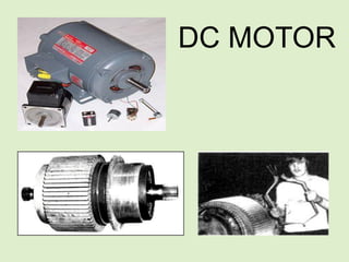
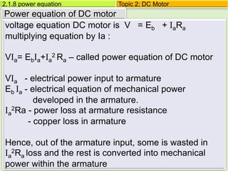
DC MOTOR
DIRECT CURRENT MOTOR
WHAT IS MOTOR?
TYPE OF DC MOTOR
• DC permanent magnet motor
• Wound serial DC motor
• Wound shunt DC motor
• Wound compound DC motor (serial/shunt)
• Universal motor (AC/DC)
• Stepping motor (stepper)
2.1.1 basic principle of operation for DC motor. Topic 2: DC motor
dc motor is:-
• convert electrical energy into mechanical
energy
• More useful than generator
• Construction similar to dc generator but
different at shaft and end cover.
• Motor are operated in open location,
therefore their construction is usually of the
protected type.
2.1.1 basic principle of operation for DC motor. Topic 2: DC motor
Energy Conversion
If electrical energy is supplied to a conductor
• lying perpendicular to a magnetic field,
• the interaction of current flowing in the conductor
• the magnetic field will produce mechanical force
(and therefore, mechanical energy)
2.1.1 basic principle of operation for DC motor. Topic 2: DC motor
Value of Mechanical Force
two conditions necessary to produce a force on the
conductor.
• conductor must be carrying current
• must be within a magnetic field.
When these two conditions exist, a force will be
applied to the conductor, which will attempt to move
the conductor in a direction perpendicular to the
magnetic field. This is the basic theory by which all
dc motors operate.
2.1.1 basic principle of operation for DC motor. Topic 2: DC motor
2.1.1 basic principle of operation for DC motor.
Value of Mechanical Force(cont…)
The force exerted upon the conductor can be
expressed as follows.
F = B i l Newton
where
B -is the density of the magnetic field,
l -length of conductor,
i -value of current flowing in the conductor.
The direction of motion can be found using
Fleming’s Left Hand Rule.
Topic 2: DC motor
Principle of operation
Induced emf
flux
2.1.2 rotation is produced in a DC motor Topic 2: DC motor
By using these three Law below can explain
the concept of Back emf
(i)Faraday’s Law
A voltage is induced any time there is relative
motion between a magnetic field and a
conductor.
(ii)Lenz’s Law
A counter voltage is always such that it will
produce (or try to produce) a current that
oppose the motion that produce it.
2.1.2 rotation is produced in a DC motor Topic 2: DC motor
(iii)Right & Lift Hand Rule
Topic 2: DC motor
2.1.2 rotation is produced in a DC motor
2.2.1 emf reverse concept
Voltage equation of a DC motor
+
-
Ia
Eb
V Supply
Voltage
Eb
Ra
Ia
-
+
V Supply
Voltage
Equlvalent circuit
Back emf in DC motor
Therefore, this induced emf is called back emf (Eb)
Eb = ØN
PZ
60a
Topic 2: DC motor
2.1.2 input voltage
Voltage equation of a DC motor
Ia
DC
supply
(Vt)
Ish Iℓ
Ra
Rsh
Ia
DC
supply
(Vt)
Is Iℓ
Ra
Rs
Shunt motor:
Iℓ = Ia+ Ish
Vt = Eb + IaRa +Vbrush
Total input power = Vt Iℓ
series motor(universal motor )
Iℓ = Ia = Is
Vt = Eb+Ia(Ra+Rs)+Vbrush
Total input power = Vt Iℓ
Back emf always less than supply voltage: Eb< Vt
Difference between Eb and Vt is very SMALL
Topic 2: DC motor
Compound motor –short shunt Compound motor –long shunt
series field
shunt
field
armature
load load
armature
series field
shunt field
Vt = E + IaRa + I𝓁Rs+ Vbrush
2.1.2 input voltage Topic 2: DC motor
Vt = E + Ia(Ra+Rs)+ Vbrush
Topic 2: DC Motor
2.1.8 power equation
Power equation of DC motor
voltage equation DC motor is V = Eb + IaRa
multiplying equation by Ia :
VIa= EbIa+Ia
2 Ra – called power equation of DC motor
VIa - electrical power input to armature
Eb Ia - electrical equation of mechanical power
developed in the armature.
Ia
2Ra - power loss at armature resistance
- copper loss in armature
Hence, out of the armature input, some is wasted in
Ia
2Ra loss and the rest is converted into mechanical
power within the armature
Topic 2: DC Motor
2.1.5 torque & speed
Formula of armature torque
Topic 2: DC Motor
2.1.5 torque & speed
Formula of shaft torque
Topic 2: DC Motor
2.1.6 torque & speed
Formula of speed
From equation of dc motor:
Eb= V - IaRa or (
ΦPnZ
a
)
V − IaRa= (
ΦPnZ
a
)
n =
v − IaRa
Φ
(
𝑎
ZP
) =
Eb
Φ
(
𝑎
ZP
)
𝑎
ZP
is constant so n =
Eb
Φ
(K) rps
It shows that speed is directly proportional to back emf
Eb and inversely to the flux Φ
n ∝
Eb
Φ
Topic 2: DC Motor
2.1.5 torque & speed
Formula of speed dc Motor
Let N1 = speed in the 1st case
I1 = armature current 1st case
Φ1 = flux/pole in the 1st case
N1 , I1, Φ1 = corresponding quantities
in the 2nd case.
Topic 2: DC Motor
2.1.5 torque & speed
Formula of speed For Series dc Motor
Than using the above relation, we get
N1 =
Eb1
Φa1
where Eb1 = V – Ia1Ra
N1 =
Eb2
Φa2
where Eb2 = V – Ia2Ra
N2
N1
=
Eb2
Eb1
x
Φa1
Φa2
prior to saturation of magnetic poles, Φ α Ia
N2
N1
=
Eb2
Eb1
x
Φ1
Φ2
and
Topic 2: DC Motor
2.1.5 torque & speed
Formula of speed For Shunt dc Motor
In this case the same equation applies,
ie
N2
N1
=
Eb2
Eb1
x
Φ1
Φ2
if Φ2 = Φ1 ,
than
N2
N1
=
Eb2
Eb1
Topic 2: DC Motor
2.1.7 related formula
Related Formula of torque &speed
The voltage generated in any machine depends
on the following factors:
1. The flux inside the machine
2. The rotation speed of the machine
3. A constant (eg
𝑎
ZP
) representing the
construction of the machine.
Topic 2: DC Motor
2.1.7 related formula
Speed regulation
The speed regulation is defined as the change in
speed when the load on the motor is reduced from
rated value to zero, expressed as per cent of the rated
load speed.
%speed regulation =
no load speed−full load speed
full load speed
x100%
=
dN
N
x 100%
Topic 2: DC Motor
2.1.8 type of dc motor
Ia
dc
supply
Ish Iℓ
Ra
Rsh
load
Shunt Motor
Value Ra vary small while Rsh large
Il = Ia + Ish,Ish =
V
Ish
Vt = Eb + IaRa + Vbrush (generally neglected)
Φ produced by the field winding is proportional to the
current passing through it (Ish) – Φ α Ish
Total input power = Vt Il
Topic 2: DC Motor
2.1.8 type of dc motor
load
Ia
DC
supply
Is Iℓ
Ra
Rs
Series Motor
Value Ra & Rsh small
Il = Ia = Ish
Vt = Eb + Ia(Ra + Rs)+ Vbrush (generally neglected)
Φ produced proportional to the armature current
Φ α Ish α I𝑎
Also called a universal motor
Topic 2: DC Motor
2.1.8 type of dc motor
Compound motor can be classified into 2 more
types
i. Cumulatively compound motors
If the magnetic fluxes produced by both series
and shunt field windings are in the same
direction (i.e., additive), the machine is called
cumulative compound.
ii. Differential compound motors
If the two fluxes are in opposition, the machine
is differential compound.
3. dc compound motor
Topic 2: DC Motor
2.1.8 type of dc motor
NOTE:-
In both these types, the connection can be
either short shunt or long shunt.
3. dc compound motor (cont…)
Topic 2: DC Motor
2.1.9 characteristic curves
Motor characteristics curves
The following factor are always used when discussing
the characteristics of the motor:-
i. Torque and armature current
–it is known as electrical characteristics
ii. Speed & armature current
iii. Speed & torque
- it is known as mechanical characteristics
The following relations should always be kept in mind:
Ta ∝ ΦIa and N ∝
Eb
Φ
Ta / Ia
N / Ia
N / Ta
Topic 2: DC Motor
2.1.9 characteristic curves
characteristics of series motor
i. Torque and armature current
In this case, as field windings also carry the
armature current, hence before saturation:
Ta ∝ ΦIa Ta ∝ Ia
2
where Φ= Ia so
Ta / Ia
I
torque(T
a
)
Ta
Tsh
Topic 2: DC Motor
2.1.9 characteristic curves
characteristics of series motor
From Eb= (
∅PnZ
a
) watt, can write as
Eb ∝ ∅N
N = (
v − IaRa
∅
)
where N ∝
Eb
∅
and Eb= V - IaRa
so
ii. Speed & armature current
speed
(N)
Ia
N / Ia
Topic 2: DC Motor
2.1.9 characteristic curves
torque(Ta)
iii. Speed & torque
- it is known as mechanical characteristics
It is found from above that when speed is high,
torque to low and vice-versa. The relation between
the two is as shown in figure
characteristics of series motor
speed
(N)
Topic 2: DC Motor
2.1.9 characteristic curves
characteristics of shunt motor
Assuming Φ to be practically constant find that
Ta ∝ Ia
Torque(T
a
)
Ia
Tsh
Ta
i. Torque and armature current Ta / Ia
Topic 2: DC Motor
2.1.9 characteristic curves
characteristics of shunt motor
if Φ is assuming constant then N ∝ Eb is also practically
constant, speed is, for most purposes, constant
ii. Speed & armature current N / Ia
speed(N)
Ia
Topic 2: DC Motor
2.1.9 characteristic curves
iii. Speed & torque
- it is known as mechanical characteristics
Can be deduced from characteristics of shunt motor
(i) and (ii) and is shown in figure below
characteristics of shunt motor
speed(N)
Ia
Topic 2: DC Motor
2.1.9 characteristic curves
Cumulatively compound dc motor
• A compound dc motor is a motor with both a shunt
and a series field.
• This winding consists of a shunt winding and a
series winding. This is also known as compound
excitation.
• The series winding can be designed as a starting
series only or as a start and run series
Topic 2: DC Motor
2.1.9 characteristic curves
Cumulatively compound dc motor
If series flux is in the same direction (figure a) the motor
call cumulative compound
If on the other hand series field opposes the shunt field
(figure b) than the motor call differential compound
Series field
Shunt field
Figure a Figure b
Topic 2: DC Motor
2.1.9 characteristic curves
Cumulatively compound dc motor
• A compound dc motor is a motor with both a shunt
and a series field.
• This winding consists of a shunt winding and a
series winding. This is also known as compound
excitation.
• The series winding can be designed as a starting
series only or as a start and run series
Equivalent circuit compound DC motor
Topic 2: DC Motor
2.1.10 relationship motor speed
• When a DC motor drives a load between no-
load and full-load, the IR will drop due to
armature resistance which is always small
compared to the voltage supply.
• This means that the counter-emf (EO) is very
nearly equal to the supply voltage (ES). The
counter-emf (EO) is expressed by
60

Zn
EO 
RELATION BETWEEN SPEED MOTOR AND THE CHANGE
OF FLUX AND ARMATURE RESISTANCE
Topic 2: DC Motor
2.1.10 relationship motor speed
Armature resistance
Equation for speed, N =
Eb
Φ
=
Vt − IaRa
Φ
k
Speed can be controlled by varying:
i. Series resistance in series with the
armature circuit – armature resistance
control
ii. The field flux(Φ) – field resistance control
iii. The applied voltage – voltage control
flux
Topic 2: DC Motor
F1 Rsh F2
IL
+
VT
-
A1
Eb
A2
Ia
Ish
Re
Ra
Re
F1 F2
Ia
A1
Eb
A2
Rs
Ra
dc shunt motor dc series motor
Figure above show method of connection of external
resistance(Re) in the armature circuit of dc machine.
Shunt machine –flux will not be affected
Series machine – flux will be affected
Both – motor run lower speed if the value Re increased.
2.1.10 relationship motor speed
Topic 2: DC Motor
Losses in the motor same as in generator.
These are:
i. Copper losses
ii. Magnetic losses
iii. Mechanical losses
The condition for maximum power developed
by the motor is
Ia Ra =
𝑉
2
= Eb
The condition for maximum efficiency is the
armature Cu losses are equal to constant
losses
2.1.13 losses & efficiency
Topic 2: DC Motor
i. Copper losses
a) Armature copper loss = I𝑎
2
R𝑎 (not EI𝑎)
This loss is about 30-40% of full-load losses
b) Field copper loss
In this case of shunt machine, it is practically
constant and same I𝑠ℎ
2
R𝑠ℎ (or VI𝑠ℎ)
In this case of series machine, it is I𝑠ℎ
2
R𝑠ℎ where
R𝑠ℎ is resistance of the series field winding.
This loss is about 20-30% of full-load losses
c) The loss due to brush contact resistance. It is
usually included in the armature copper losses.
2.1.13 losses & efficiency
Topic 2: DC Motor
ii. Magnetic losses (also know as iron or core losses)
a) Hysteresis loss, 𝑊ℎ α B𝑚𝑎𝑥
1.6
b) Eddy current loss, 𝑊ℎ α B𝑚𝑎𝑥
2
𝑓2
These losses are practically constant for shunt and
compound-wound machine because in their case,
field current is approximately constant.
Both these losses total up to about 20 to 30% full
load losses
2.1.13 losses & efficiency
Topic 2: DC Motor
iii. Mechanical losses
These consist of:
a) Friction loss at bearings and commentator
b) Air-Friction or Windage loss of rotating armature
These are about 1 to 20% of full load losses
2.1.13 losses & efficiency
Topic 2: DC Motor
Total losses in a dc machine are summarized :
2.1.13 losses & efficiency
Total
losses
copper
losses
Iron
losses
Mechanical
losses
Armature Cu loss
shunt Cu loss
series Cu loss
Eddy current loss
Hysteresis loss
Friction
Windage
Topic 2: DC Motor
Total copper loss = Field loss + Armature loss
Power developed and converted into mechanical
power,
Power developed = Input power – Total copper loss
The output power and torque are less than the
developed values
Power output = Power developed – rotational losses
2.1.13 losses & efficiency
Topic 2: DC Motor
2.1.13 losses & efficiency
Power stage : various power stages in the case of a dc
generator are shown below:
Motor
input
VI watt
Driving
power in
armature
= E𝑏 I𝑎
watts
Output in
watts or
B.H.P x
735.5watts
copper
losses
Iron and
friction
losses
A
B
C
Topic 2: DC Motor
2.1.13 losses & efficiency
Following are the three efficiencies:
1. electrical efficiencies:
η𝑚 =
𝐵
𝐴
= Driving power in armature
𝑚𝑒𝑐ℎ𝑎𝑛𝑖𝑐𝑎𝑙 𝑝𝑜𝑤𝑒𝑟 𝑠𝑢𝑝𝑝𝑙𝑖𝑒𝑑
=
E𝑏 I𝑎
𝑜𝑢𝑡𝑝𝑢𝑡 𝑜𝑓 𝑑𝑟𝑖𝑣𝑖𝑛𝑔 𝑒𝑛𝑔𝑖𝑛𝑒
2. Mechanical efficiencies:
η𝑒 =
𝐶
𝐵
=
𝑤𝑎𝑡𝑡𝑠 𝑎𝑣𝑎𝑖𝑙𝑎𝑏𝑙𝑒 𝑖𝑛 𝑙𝑜𝑎𝑑 𝑐𝑖𝑟𝑐𝑢𝑖𝑡
𝑡𝑜𝑡𝑎𝑙 𝑤𝑎𝑡𝑡𝑠 𝑔𝑒𝑛𝑒𝑟𝑎𝑡𝑒𝑑
=
𝑉I
𝐸I𝑎
3. Overall or commercial efficiencies :
η𝑐 =
𝐶
𝐴
=
𝑤𝑎𝑡𝑡𝑠 𝑎𝑣𝑎𝑖𝑙𝑎𝑏𝑙𝑒 𝑖𝑛 𝑙𝑜𝑎𝑑 𝑐𝑖𝑟𝑐𝑢𝑖𝑡
𝑚𝑒𝑐ℎ𝑎𝑛𝑖𝑐𝑎𝑙 𝑝𝑜𝑤𝑒𝑟 𝑠𝑢𝑝𝑝𝑙𝑖𝑒𝑑
Ir is obvious that overall efficiencies η𝑐 = η𝑚 + η𝑒
good generator value efficiencies may be high (95%)
Topic 2: DC Motor
Efficiency of the motor can be calculated as the ratio
of output power to the input power.
Total electrical input power, Pin = Vt Ia + Vf If
Power absorbed by the field winding is in turn
converted to heat and is given by:
Pfield loss = If
2
Rf = (
Vf
Rf
)
2
Rf
Some power is lost in the resistance of the armature
winding and can be calculated as:
Parmature loss = Ia
2
Ra
2.1.13 losses & efficiency
Topic 2: DC Motor
Generator or motor, the efficiency is equal to the
output divided by the input.
However in a generator the input is mechanical
and output is electrical.
In a motor the opposite is true, therefor:
Efficiency (η) =
Pout
Pin
x100%
2.1.13 losses & efficiency
Topic 2: DC Motor
Shunt dc Motor
• cannot carry high currents, it is unsuitable for
applications requiring a high starting torque.
• So, it requires its shaft load to be small to start
functioning
• are very suitable for belt-driven applications. turns
at almost constant speed if the voltage is fixed.
• can deliver increasing torque, without an
appreciable reduction in speed, by increasing the
motor current.
• Fixed speed applications such as automotive
windscreen wipers and fans.
2.1.14 application
Topic 2: DC Motor
Series dc motor
• is an industry workhorse for both high and low
power, fixed and variable speed electric drives.
• Applications range from cheap toys to automotive
applications.
• They are inexpensive to manufacture and are
used in variable speed household appliances such
as sewing machines, cheap toys to automotive &
power tools
• Its high starting torque makes it particularly
suitable for a wide range of traction applications.
2.1.14 application
Topic 2: DC Motor
separately excited motor
• has independent voltage supplies to the field and
rotor windings allowing more control over the
motor performance.
• Characteristics The voltage on either the field or
the rotor windings can be used to control the
speed and torque of a separately excited motor.
• Applications Train and automotive traction
applications
2.1.14 application
Topic 2: DC Motor
2.1.14 application
type of
motor
characteristics application
shunt Approximately
constant speed
Adjustable
speed
Medium starting
torque
For driving constant speed
line shafting ie:
Lathes (pelarik)
Centrifugal pump
Machine tools
Blowers and fans
Reciprocating pumps
Topic 2: DC Motor
2.1.14 application
type of
motor
characteristics application
series Variable speed
Adjustable
varying speed
High starting
torque
For traction work ie:
Electric locomotives
Rapid transit systems
Trolley car etc.
Cranes and hoists
Conveyors
Topic 2: DC Motor
2.1.14 application
type of
motor
characteristics application
Cumulative
compound
Variable speed
Adjustable
varying speed
High starting
torque
For intermittent high
torque loads:
For shears and
punches:
elevators
Conveyors
Heavy planers
Rolling mills
Topic 2: DC Motor
Universal Motors
• In a series wound DC motor, reversing either the
field winding leads or the rotor winding leads will
reverse the direction of the motor.
• However, simply reversing the leads from the
power supply will have no effect on the direction of
rotation since it is equivalent to reversing the
current through both the individual windings - in
effect a double reversal.
• In other words the motor will turn in the same
direction even though the current through the
series windings is reversed.
2.1.14 application
Topic 2: DC Motor
Universal Motors (cont…)
• This means that the motor can run on alternating
current as well as direct current since the direction
of rotation is independent of the direction of the
current through the series windings.
• Universal motors are often used in power tools
and household appliances such as vacuum
cleaners and food mixers
2.1.14 application

DC MOTOR.pdf

  • 1.
  • 3.
  • 4.
    TYPE OF DCMOTOR • DC permanent magnet motor • Wound serial DC motor • Wound shunt DC motor • Wound compound DC motor (serial/shunt) • Universal motor (AC/DC) • Stepping motor (stepper) 2.1.1 basic principle of operation for DC motor. Topic 2: DC motor
  • 5.
    dc motor is:- •convert electrical energy into mechanical energy • More useful than generator • Construction similar to dc generator but different at shaft and end cover. • Motor are operated in open location, therefore their construction is usually of the protected type. 2.1.1 basic principle of operation for DC motor. Topic 2: DC motor
  • 6.
    Energy Conversion If electricalenergy is supplied to a conductor • lying perpendicular to a magnetic field, • the interaction of current flowing in the conductor • the magnetic field will produce mechanical force (and therefore, mechanical energy) 2.1.1 basic principle of operation for DC motor. Topic 2: DC motor
  • 7.
    Value of MechanicalForce two conditions necessary to produce a force on the conductor. • conductor must be carrying current • must be within a magnetic field. When these two conditions exist, a force will be applied to the conductor, which will attempt to move the conductor in a direction perpendicular to the magnetic field. This is the basic theory by which all dc motors operate. 2.1.1 basic principle of operation for DC motor. Topic 2: DC motor
  • 8.
    2.1.1 basic principleof operation for DC motor. Value of Mechanical Force(cont…) The force exerted upon the conductor can be expressed as follows. F = B i l Newton where B -is the density of the magnetic field, l -length of conductor, i -value of current flowing in the conductor. The direction of motion can be found using Fleming’s Left Hand Rule. Topic 2: DC motor
  • 9.
    Principle of operation Inducedemf flux 2.1.2 rotation is produced in a DC motor Topic 2: DC motor
  • 10.
    By using thesethree Law below can explain the concept of Back emf (i)Faraday’s Law A voltage is induced any time there is relative motion between a magnetic field and a conductor. (ii)Lenz’s Law A counter voltage is always such that it will produce (or try to produce) a current that oppose the motion that produce it. 2.1.2 rotation is produced in a DC motor Topic 2: DC motor
  • 11.
    (iii)Right & LiftHand Rule Topic 2: DC motor 2.1.2 rotation is produced in a DC motor
  • 12.
    2.2.1 emf reverseconcept Voltage equation of a DC motor + - Ia Eb V Supply Voltage Eb Ra Ia - + V Supply Voltage Equlvalent circuit Back emf in DC motor Therefore, this induced emf is called back emf (Eb) Eb = ØN PZ 60a Topic 2: DC motor
  • 13.
    2.1.2 input voltage Voltageequation of a DC motor Ia DC supply (Vt) Ish Iℓ Ra Rsh Ia DC supply (Vt) Is Iℓ Ra Rs Shunt motor: Iℓ = Ia+ Ish Vt = Eb + IaRa +Vbrush Total input power = Vt Iℓ series motor(universal motor ) Iℓ = Ia = Is Vt = Eb+Ia(Ra+Rs)+Vbrush Total input power = Vt Iℓ Back emf always less than supply voltage: Eb< Vt Difference between Eb and Vt is very SMALL Topic 2: DC motor
  • 14.
    Compound motor –shortshunt Compound motor –long shunt series field shunt field armature load load armature series field shunt field Vt = E + IaRa + I𝓁Rs+ Vbrush 2.1.2 input voltage Topic 2: DC motor Vt = E + Ia(Ra+Rs)+ Vbrush
  • 15.
    Topic 2: DCMotor 2.1.8 power equation Power equation of DC motor voltage equation DC motor is V = Eb + IaRa multiplying equation by Ia : VIa= EbIa+Ia 2 Ra – called power equation of DC motor VIa - electrical power input to armature Eb Ia - electrical equation of mechanical power developed in the armature. Ia 2Ra - power loss at armature resistance - copper loss in armature Hence, out of the armature input, some is wasted in Ia 2Ra loss and the rest is converted into mechanical power within the armature
  • 16.
    Topic 2: DCMotor 2.1.5 torque & speed Formula of armature torque
  • 17.
    Topic 2: DCMotor 2.1.5 torque & speed Formula of shaft torque
  • 18.
    Topic 2: DCMotor 2.1.6 torque & speed Formula of speed From equation of dc motor: Eb= V - IaRa or ( ΦPnZ a ) V − IaRa= ( ΦPnZ a ) n = v − IaRa Φ ( 𝑎 ZP ) = Eb Φ ( 𝑎 ZP ) 𝑎 ZP is constant so n = Eb Φ (K) rps It shows that speed is directly proportional to back emf Eb and inversely to the flux Φ n ∝ Eb Φ
  • 19.
    Topic 2: DCMotor 2.1.5 torque & speed Formula of speed dc Motor Let N1 = speed in the 1st case I1 = armature current 1st case Φ1 = flux/pole in the 1st case N1 , I1, Φ1 = corresponding quantities in the 2nd case.
  • 20.
    Topic 2: DCMotor 2.1.5 torque & speed Formula of speed For Series dc Motor Than using the above relation, we get N1 = Eb1 Φa1 where Eb1 = V – Ia1Ra N1 = Eb2 Φa2 where Eb2 = V – Ia2Ra N2 N1 = Eb2 Eb1 x Φa1 Φa2 prior to saturation of magnetic poles, Φ α Ia N2 N1 = Eb2 Eb1 x Φ1 Φ2 and
  • 21.
    Topic 2: DCMotor 2.1.5 torque & speed Formula of speed For Shunt dc Motor In this case the same equation applies, ie N2 N1 = Eb2 Eb1 x Φ1 Φ2 if Φ2 = Φ1 , than N2 N1 = Eb2 Eb1
  • 22.
    Topic 2: DCMotor 2.1.7 related formula Related Formula of torque &speed The voltage generated in any machine depends on the following factors: 1. The flux inside the machine 2. The rotation speed of the machine 3. A constant (eg 𝑎 ZP ) representing the construction of the machine.
  • 23.
    Topic 2: DCMotor 2.1.7 related formula Speed regulation The speed regulation is defined as the change in speed when the load on the motor is reduced from rated value to zero, expressed as per cent of the rated load speed. %speed regulation = no load speed−full load speed full load speed x100% = dN N x 100%
  • 24.
    Topic 2: DCMotor 2.1.8 type of dc motor Ia dc supply Ish Iℓ Ra Rsh load Shunt Motor Value Ra vary small while Rsh large Il = Ia + Ish,Ish = V Ish Vt = Eb + IaRa + Vbrush (generally neglected) Φ produced by the field winding is proportional to the current passing through it (Ish) – Φ α Ish Total input power = Vt Il
  • 25.
    Topic 2: DCMotor 2.1.8 type of dc motor load Ia DC supply Is Iℓ Ra Rs Series Motor Value Ra & Rsh small Il = Ia = Ish Vt = Eb + Ia(Ra + Rs)+ Vbrush (generally neglected) Φ produced proportional to the armature current Φ α Ish α I𝑎 Also called a universal motor
  • 26.
    Topic 2: DCMotor 2.1.8 type of dc motor Compound motor can be classified into 2 more types i. Cumulatively compound motors If the magnetic fluxes produced by both series and shunt field windings are in the same direction (i.e., additive), the machine is called cumulative compound. ii. Differential compound motors If the two fluxes are in opposition, the machine is differential compound. 3. dc compound motor
  • 27.
    Topic 2: DCMotor 2.1.8 type of dc motor NOTE:- In both these types, the connection can be either short shunt or long shunt. 3. dc compound motor (cont…)
  • 28.
    Topic 2: DCMotor 2.1.9 characteristic curves Motor characteristics curves The following factor are always used when discussing the characteristics of the motor:- i. Torque and armature current –it is known as electrical characteristics ii. Speed & armature current iii. Speed & torque - it is known as mechanical characteristics The following relations should always be kept in mind: Ta ∝ ΦIa and N ∝ Eb Φ Ta / Ia N / Ia N / Ta
  • 29.
    Topic 2: DCMotor 2.1.9 characteristic curves characteristics of series motor i. Torque and armature current In this case, as field windings also carry the armature current, hence before saturation: Ta ∝ ΦIa Ta ∝ Ia 2 where Φ= Ia so Ta / Ia I torque(T a ) Ta Tsh
  • 30.
    Topic 2: DCMotor 2.1.9 characteristic curves characteristics of series motor From Eb= ( ∅PnZ a ) watt, can write as Eb ∝ ∅N N = ( v − IaRa ∅ ) where N ∝ Eb ∅ and Eb= V - IaRa so ii. Speed & armature current speed (N) Ia N / Ia
  • 31.
    Topic 2: DCMotor 2.1.9 characteristic curves torque(Ta) iii. Speed & torque - it is known as mechanical characteristics It is found from above that when speed is high, torque to low and vice-versa. The relation between the two is as shown in figure characteristics of series motor speed (N)
  • 32.
    Topic 2: DCMotor 2.1.9 characteristic curves characteristics of shunt motor Assuming Φ to be practically constant find that Ta ∝ Ia Torque(T a ) Ia Tsh Ta i. Torque and armature current Ta / Ia
  • 33.
    Topic 2: DCMotor 2.1.9 characteristic curves characteristics of shunt motor if Φ is assuming constant then N ∝ Eb is also practically constant, speed is, for most purposes, constant ii. Speed & armature current N / Ia speed(N) Ia
  • 34.
    Topic 2: DCMotor 2.1.9 characteristic curves iii. Speed & torque - it is known as mechanical characteristics Can be deduced from characteristics of shunt motor (i) and (ii) and is shown in figure below characteristics of shunt motor speed(N) Ia
  • 35.
    Topic 2: DCMotor 2.1.9 characteristic curves Cumulatively compound dc motor • A compound dc motor is a motor with both a shunt and a series field. • This winding consists of a shunt winding and a series winding. This is also known as compound excitation. • The series winding can be designed as a starting series only or as a start and run series
  • 36.
    Topic 2: DCMotor 2.1.9 characteristic curves Cumulatively compound dc motor If series flux is in the same direction (figure a) the motor call cumulative compound If on the other hand series field opposes the shunt field (figure b) than the motor call differential compound Series field Shunt field Figure a Figure b
  • 37.
    Topic 2: DCMotor 2.1.9 characteristic curves Cumulatively compound dc motor • A compound dc motor is a motor with both a shunt and a series field. • This winding consists of a shunt winding and a series winding. This is also known as compound excitation. • The series winding can be designed as a starting series only or as a start and run series Equivalent circuit compound DC motor
  • 38.
    Topic 2: DCMotor 2.1.10 relationship motor speed • When a DC motor drives a load between no- load and full-load, the IR will drop due to armature resistance which is always small compared to the voltage supply. • This means that the counter-emf (EO) is very nearly equal to the supply voltage (ES). The counter-emf (EO) is expressed by 60  Zn EO  RELATION BETWEEN SPEED MOTOR AND THE CHANGE OF FLUX AND ARMATURE RESISTANCE
  • 39.
    Topic 2: DCMotor 2.1.10 relationship motor speed Armature resistance Equation for speed, N = Eb Φ = Vt − IaRa Φ k Speed can be controlled by varying: i. Series resistance in series with the armature circuit – armature resistance control ii. The field flux(Φ) – field resistance control iii. The applied voltage – voltage control
  • 40.
    flux Topic 2: DCMotor F1 Rsh F2 IL + VT - A1 Eb A2 Ia Ish Re Ra Re F1 F2 Ia A1 Eb A2 Rs Ra dc shunt motor dc series motor Figure above show method of connection of external resistance(Re) in the armature circuit of dc machine. Shunt machine –flux will not be affected Series machine – flux will be affected Both – motor run lower speed if the value Re increased. 2.1.10 relationship motor speed
  • 41.
    Topic 2: DCMotor Losses in the motor same as in generator. These are: i. Copper losses ii. Magnetic losses iii. Mechanical losses The condition for maximum power developed by the motor is Ia Ra = 𝑉 2 = Eb The condition for maximum efficiency is the armature Cu losses are equal to constant losses 2.1.13 losses & efficiency
  • 42.
    Topic 2: DCMotor i. Copper losses a) Armature copper loss = I𝑎 2 R𝑎 (not EI𝑎) This loss is about 30-40% of full-load losses b) Field copper loss In this case of shunt machine, it is practically constant and same I𝑠ℎ 2 R𝑠ℎ (or VI𝑠ℎ) In this case of series machine, it is I𝑠ℎ 2 R𝑠ℎ where R𝑠ℎ is resistance of the series field winding. This loss is about 20-30% of full-load losses c) The loss due to brush contact resistance. It is usually included in the armature copper losses. 2.1.13 losses & efficiency
  • 43.
    Topic 2: DCMotor ii. Magnetic losses (also know as iron or core losses) a) Hysteresis loss, 𝑊ℎ α B𝑚𝑎𝑥 1.6 b) Eddy current loss, 𝑊ℎ α B𝑚𝑎𝑥 2 𝑓2 These losses are practically constant for shunt and compound-wound machine because in their case, field current is approximately constant. Both these losses total up to about 20 to 30% full load losses 2.1.13 losses & efficiency
  • 44.
    Topic 2: DCMotor iii. Mechanical losses These consist of: a) Friction loss at bearings and commentator b) Air-Friction or Windage loss of rotating armature These are about 1 to 20% of full load losses 2.1.13 losses & efficiency
  • 45.
    Topic 2: DCMotor Total losses in a dc machine are summarized : 2.1.13 losses & efficiency Total losses copper losses Iron losses Mechanical losses Armature Cu loss shunt Cu loss series Cu loss Eddy current loss Hysteresis loss Friction Windage
  • 46.
    Topic 2: DCMotor Total copper loss = Field loss + Armature loss Power developed and converted into mechanical power, Power developed = Input power – Total copper loss The output power and torque are less than the developed values Power output = Power developed – rotational losses 2.1.13 losses & efficiency
  • 47.
    Topic 2: DCMotor 2.1.13 losses & efficiency Power stage : various power stages in the case of a dc generator are shown below: Motor input VI watt Driving power in armature = E𝑏 I𝑎 watts Output in watts or B.H.P x 735.5watts copper losses Iron and friction losses A B C
  • 48.
    Topic 2: DCMotor 2.1.13 losses & efficiency Following are the three efficiencies: 1. electrical efficiencies: η𝑚 = 𝐵 𝐴 = Driving power in armature 𝑚𝑒𝑐ℎ𝑎𝑛𝑖𝑐𝑎𝑙 𝑝𝑜𝑤𝑒𝑟 𝑠𝑢𝑝𝑝𝑙𝑖𝑒𝑑 = E𝑏 I𝑎 𝑜𝑢𝑡𝑝𝑢𝑡 𝑜𝑓 𝑑𝑟𝑖𝑣𝑖𝑛𝑔 𝑒𝑛𝑔𝑖𝑛𝑒 2. Mechanical efficiencies: η𝑒 = 𝐶 𝐵 = 𝑤𝑎𝑡𝑡𝑠 𝑎𝑣𝑎𝑖𝑙𝑎𝑏𝑙𝑒 𝑖𝑛 𝑙𝑜𝑎𝑑 𝑐𝑖𝑟𝑐𝑢𝑖𝑡 𝑡𝑜𝑡𝑎𝑙 𝑤𝑎𝑡𝑡𝑠 𝑔𝑒𝑛𝑒𝑟𝑎𝑡𝑒𝑑 = 𝑉I 𝐸I𝑎 3. Overall or commercial efficiencies : η𝑐 = 𝐶 𝐴 = 𝑤𝑎𝑡𝑡𝑠 𝑎𝑣𝑎𝑖𝑙𝑎𝑏𝑙𝑒 𝑖𝑛 𝑙𝑜𝑎𝑑 𝑐𝑖𝑟𝑐𝑢𝑖𝑡 𝑚𝑒𝑐ℎ𝑎𝑛𝑖𝑐𝑎𝑙 𝑝𝑜𝑤𝑒𝑟 𝑠𝑢𝑝𝑝𝑙𝑖𝑒𝑑 Ir is obvious that overall efficiencies η𝑐 = η𝑚 + η𝑒 good generator value efficiencies may be high (95%)
  • 49.
    Topic 2: DCMotor Efficiency of the motor can be calculated as the ratio of output power to the input power. Total electrical input power, Pin = Vt Ia + Vf If Power absorbed by the field winding is in turn converted to heat and is given by: Pfield loss = If 2 Rf = ( Vf Rf ) 2 Rf Some power is lost in the resistance of the armature winding and can be calculated as: Parmature loss = Ia 2 Ra 2.1.13 losses & efficiency
  • 50.
    Topic 2: DCMotor Generator or motor, the efficiency is equal to the output divided by the input. However in a generator the input is mechanical and output is electrical. In a motor the opposite is true, therefor: Efficiency (η) = Pout Pin x100% 2.1.13 losses & efficiency
  • 51.
    Topic 2: DCMotor Shunt dc Motor • cannot carry high currents, it is unsuitable for applications requiring a high starting torque. • So, it requires its shaft load to be small to start functioning • are very suitable for belt-driven applications. turns at almost constant speed if the voltage is fixed. • can deliver increasing torque, without an appreciable reduction in speed, by increasing the motor current. • Fixed speed applications such as automotive windscreen wipers and fans. 2.1.14 application
  • 52.
    Topic 2: DCMotor Series dc motor • is an industry workhorse for both high and low power, fixed and variable speed electric drives. • Applications range from cheap toys to automotive applications. • They are inexpensive to manufacture and are used in variable speed household appliances such as sewing machines, cheap toys to automotive & power tools • Its high starting torque makes it particularly suitable for a wide range of traction applications. 2.1.14 application
  • 53.
    Topic 2: DCMotor separately excited motor • has independent voltage supplies to the field and rotor windings allowing more control over the motor performance. • Characteristics The voltage on either the field or the rotor windings can be used to control the speed and torque of a separately excited motor. • Applications Train and automotive traction applications 2.1.14 application
  • 54.
    Topic 2: DCMotor 2.1.14 application type of motor characteristics application shunt Approximately constant speed Adjustable speed Medium starting torque For driving constant speed line shafting ie: Lathes (pelarik) Centrifugal pump Machine tools Blowers and fans Reciprocating pumps
  • 55.
    Topic 2: DCMotor 2.1.14 application type of motor characteristics application series Variable speed Adjustable varying speed High starting torque For traction work ie: Electric locomotives Rapid transit systems Trolley car etc. Cranes and hoists Conveyors
  • 56.
    Topic 2: DCMotor 2.1.14 application type of motor characteristics application Cumulative compound Variable speed Adjustable varying speed High starting torque For intermittent high torque loads: For shears and punches: elevators Conveyors Heavy planers Rolling mills
  • 57.
    Topic 2: DCMotor Universal Motors • In a series wound DC motor, reversing either the field winding leads or the rotor winding leads will reverse the direction of the motor. • However, simply reversing the leads from the power supply will have no effect on the direction of rotation since it is equivalent to reversing the current through both the individual windings - in effect a double reversal. • In other words the motor will turn in the same direction even though the current through the series windings is reversed. 2.1.14 application
  • 58.
    Topic 2: DCMotor Universal Motors (cont…) • This means that the motor can run on alternating current as well as direct current since the direction of rotation is independent of the direction of the current through the series windings. • Universal motors are often used in power tools and household appliances such as vacuum cleaners and food mixers 2.1.14 application