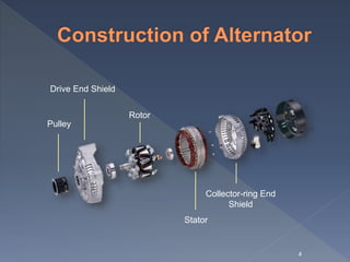
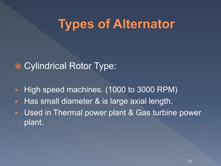
1
 Definition
 Construction of Alternator
 Working Principal of Alternator
 Types of Alternator
2
 An alternator is an electrical generator that
converts mechanical energy to electrical energy
in the form of alternating current. Most
alternators use a rotating magnetic field with
stationary armature.
 It is also known as synchronous generator.
3
Pulley
Drive End Shield
Rotor
Stator
Collector-ring End
Shield
4
 Stator:
 The stator is the stationary part of the alternator.
 It works as a armature in synchronous machine.
 The armature winding is housed in it.
5
 Rotor:
 Rotor is the rotating part of the synchronous
machine.
 It works as a field of the synchronous machine.
 Field winding is housed on it.
 Field winding is excited by DC supply through
brushes and slip ring.
6
 The working principle of alternator depends
upon Faraday’s law of electromagnetic
induction-
The current is induced in the conductor
inside a magnetic field when there is a
relative motion between that conductor &
the magnetic field.
7
 For understanding working of alternator let’s assume a
single rectangular turn placed in between two opposite
magnetic pole as shown.
 The single turn loop ABCD starts rotating clockwise
against a-b.
8
 After 90° rotation the side AB or conductor AB of the loop comes in
front of S-pole & conductor CD comes in front of N-pole.
 As per Fleming right hand rule the direction of this current will be from
A to B. At the same time conductor CD comes under N-pole & here
also if we apply Fleming right hand rule we will get the direction of
induced current & it will be from C to D.
9
 Now after clockwise rotation of another 90° the turn ABCD comes at
vertical position as shown below. At this position tangential motion of
conductor AB and CD is just parallel to the magnetic flux lines, hence there
will be no flux cutting that is no current in the conductor.
 While the turn ABCD comes from horizontal position to vertical position,
angle between flux lines and direction of motion of conductor, reduces from
90° to 0° and consequently the induced current in the turn is reduced to
zero from its maximum value.
10
 As at this position the turn comes at horizontal position from its vertical
position, the current in the conductors comes to its maximum value from zero.
That means current is circulating in the close turn from point B to A, from A to
D, from D to C and from C to B
 During every full revolution of the turn, the current in the turn gradually
reaches to its maximum value then reduces to zero and then again it comes to
its maximum value but in opposite direction and again it comes to zero.
 In this way the current completes one full sine wave form during each 360°
revolution of the turn. Thus an alternating current is produced in a turn is
rotated inside a magnetic field. From this, we come to the actual working
principle of alternator.
11
 Synchronous generators are classified in two
category according to its rotor construction:
1. Cylindrical Rotor Type
2. Salient Pole Rotor Type
12
 Cylindrical Rotor Type:
 High speed machines. (1000 to 3000 RPM)
 Has small diameter & is large axial length.
 Used in Thermal power plant & Gas turbine power
plant.
13
14
 Salient Pole Rotor Type:
 Low speed machines. (50 to 500 rpm)
 Has large diameter & is small axial length.
 Used in Hydro power plant.
15
16
Thank You
17

Alternator

  • 1.
  • 2.
     Definition  Constructionof Alternator  Working Principal of Alternator  Types of Alternator 2
  • 3.
     An alternatoris an electrical generator that converts mechanical energy to electrical energy in the form of alternating current. Most alternators use a rotating magnetic field with stationary armature.  It is also known as synchronous generator. 3
  • 4.
  • 5.
     Stator:  Thestator is the stationary part of the alternator.  It works as a armature in synchronous machine.  The armature winding is housed in it. 5
  • 6.
     Rotor:  Rotoris the rotating part of the synchronous machine.  It works as a field of the synchronous machine.  Field winding is housed on it.  Field winding is excited by DC supply through brushes and slip ring. 6
  • 7.
     The workingprinciple of alternator depends upon Faraday’s law of electromagnetic induction- The current is induced in the conductor inside a magnetic field when there is a relative motion between that conductor & the magnetic field. 7
  • 8.
     For understandingworking of alternator let’s assume a single rectangular turn placed in between two opposite magnetic pole as shown.  The single turn loop ABCD starts rotating clockwise against a-b. 8
  • 9.
     After 90°rotation the side AB or conductor AB of the loop comes in front of S-pole & conductor CD comes in front of N-pole.  As per Fleming right hand rule the direction of this current will be from A to B. At the same time conductor CD comes under N-pole & here also if we apply Fleming right hand rule we will get the direction of induced current & it will be from C to D. 9
  • 10.
     Now afterclockwise rotation of another 90° the turn ABCD comes at vertical position as shown below. At this position tangential motion of conductor AB and CD is just parallel to the magnetic flux lines, hence there will be no flux cutting that is no current in the conductor.  While the turn ABCD comes from horizontal position to vertical position, angle between flux lines and direction of motion of conductor, reduces from 90° to 0° and consequently the induced current in the turn is reduced to zero from its maximum value. 10
  • 11.
     As atthis position the turn comes at horizontal position from its vertical position, the current in the conductors comes to its maximum value from zero. That means current is circulating in the close turn from point B to A, from A to D, from D to C and from C to B  During every full revolution of the turn, the current in the turn gradually reaches to its maximum value then reduces to zero and then again it comes to its maximum value but in opposite direction and again it comes to zero.  In this way the current completes one full sine wave form during each 360° revolution of the turn. Thus an alternating current is produced in a turn is rotated inside a magnetic field. From this, we come to the actual working principle of alternator. 11
  • 12.
     Synchronous generatorsare classified in two category according to its rotor construction: 1. Cylindrical Rotor Type 2. Salient Pole Rotor Type 12
  • 13.
     Cylindrical RotorType:  High speed machines. (1000 to 3000 RPM)  Has small diameter & is large axial length.  Used in Thermal power plant & Gas turbine power plant. 13
  • 14.
  • 15.
     Salient PoleRotor Type:  Low speed machines. (50 to 500 rpm)  Has large diameter & is small axial length.  Used in Hydro power plant. 15
  • 16.
  • 17.