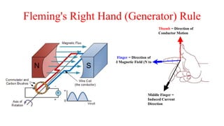
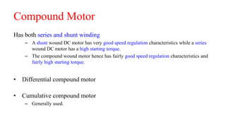
DC Motor
By Dhruv Upadhaya
Motor
• Motor is a device which converts electrical energy into
mechanical energy.
• Depending upon the energy source the motor can be either ac
or dc.
• AC- Alternating Current
• DC- Direct Current
Basics
An Electric Field or Force Surrounding a Charged Particle
An electric field radiates outward
from a positive charge and radiates in
toward a negative point charge.
•The movement of Electric Charges is called Current.
• Current is measured by the amount of charge (Coulombs) passing
through the cross-sectional area of a conductor in a given period of
time (Seconds).
R
When current moves
through a conductor a
circular magnetic field is
induced around the
conductor
Magnetic Field Lines
Negative Battery
Terminal
Positive Battery
Terminal
The Right Hand Rule
Current Coming Towards You Current Moving Away From You
When current moves through a coiled
conductor a circular magnetic field is induced
about the coil
Current and Magnetism in a Coil
Induced Magnetic Field (Due
to current)
Fixed Magnetic Field
A Conductor in a Fixed
Magnetic Field A Current Carrying
Conductor in a Fixed
Magnetic Field
Force
Fleming's Left Hand (Motor) Rule
Determines the direction of DC current carrying conductor in a
fixed magnetic field
Thumb = Direction of
Conductor Motion
Fore Finger = Direction of
Fixed Magnetic Field (N to
S)
Middle Finger =
Conventional Current
Direction
The magnetic field surrounding a current carrying
conductor interacts with an existing magnetic
field.
Direction of Force (Torque) acting to turn the Armature
(Conductor)
N
S
Electric and magnetic fields: Lorentz force
• A current-carrying wire in a magnetic field experiences a force.
• The magnitude and direction of this force depend on four variables: the
magnitude and direction of the current (I), the length of the wire (L), the
strength and direction of the magnetic field (B), and the angle between the field
and the wire (Θ).
F = I L X B Or in scalar terms: F = I L B SinΘ
When current is in amperes, length in meters, and magnetic field in teslas, the
force is in newtons.
• The direction of the force is perpendicular to both the current and the magnetic
field, and is predicted by the right-hand cross-product rule.
Fleming's Right Hand (Generator) Rule
Thumb = Direction of
Conductor Motion
Fore Finger = Direction of
Fixed Magnetic Field (N to
S)
Middle Finger =
Induced Current
Direction
The Armature of a Brush Commutated DC Motor is made up of Current Carrying
Conductors Wrapped Around an Iron Core
The Motor Armature is an electro Magnet and Operates according
to the Principles Described in this Slide Show
Brushed DC Motor
EMF equation
Let,
𝜙 = Flux per pole in weber
𝑍 = Total number of conductor
𝑃 = Number of poles
𝐴 = Number of parallel paths
𝑁 = Armature speed in rpm
𝐸 𝑏 = Emf generated in any one of the parallel path
Flux cut by 1 conductor in 1 revolution = 𝑃𝜙
Flux cut by 1 conductor in 60 sec =
𝑃𝜙𝑁
60
Avg emf generated in 1conductor =
𝑃𝜙𝑁
60
Number of conductors in each parallel path =
𝑍
𝐴
𝐸 𝑏 =
𝑃𝜙𝑁𝑍
60𝐴
Equivalent Circuit Diagram of Motor
Current Flows from battery to motor so by
applying KVL
V= Eb + IaRa + Vb
Torque Equation
Voltage Equation of DC motor
𝑉 = 𝐸 𝑏 + 𝐼 𝑎 𝑅 𝑎
Multiplying both sides by Ia
𝑉𝐼 𝑎 = 𝐸 𝑏 𝐼 𝑎 + 𝐼 𝑎
2
𝑅 𝑎
Electrical
Power input to
motor
Copper loss in
armatureGross
Mechanical
Power to Shaft
𝑃𝑚 = 𝜔𝜏 𝑎𝑣 = 2𝜋𝑛𝜏 𝑎𝑣 = 𝐸 𝑏 𝐼 𝑎 =
𝑃𝜙𝑛𝑍
𝐴
𝐼 𝑎
𝜏 𝑎𝑣 =
𝑃𝑍
2𝜋𝐴
𝜙𝐼 𝑎
Constant
𝜏 𝑎𝑣 ∝ 𝜙𝐼 𝑎
Classification of DC motors
DC motors are mainly classified into three types as listed below:
• Shunt Excited Motor
• Series Excited Motor
• Compound Motor
• Differential Compound
• Cumulative Compound
Shunt Excited Motor
Rsh
Ia
Il
V
Ish
Eb
• 𝐼𝑙 = 𝐼 𝑎 + 𝐼𝑠ℎ
• 𝑉 = 𝐼𝑠ℎ 𝑅 𝑠ℎ
• 𝑉 = 𝐸 𝑏 + 𝐼 𝑎 𝑅 𝑎
Series Excited Motor
• 𝐼𝑙 = 𝐼 𝑎 = 𝐼𝑠𝑒
• 𝑉 = 𝐸 𝑏 + 𝐼 𝑎(𝑅 𝑎+𝑅 𝑠𝑒)
Characteristic of DC motors
Torque - Armature current characteristic
Speed - Armature current characteristic
Speed - Torque characteristic
Shunt Excited Motor
• Speed - Armature current characteristic
𝐸 𝑏 =
𝑃𝜙𝑁𝑍
𝐴
𝑁 ∝
𝑉 − 𝐼 𝑎 𝑅 𝑎
𝜙
𝜙 remains constant in shunt motor so
𝑁 ∝ 𝑉 − 𝐼 𝑎 𝑅 𝑎
𝐼 𝑎 𝑅 𝑎would be very small and V is constant so the motor will
have a constant speed so aka constant speed motor.
Rsh
Ia
Il
V
Ish
Eb
Shunt Excited Motor
• Torque - Armature current characteristic
𝜏 𝑎𝑣 ∝ 𝜙𝐼 𝑎
𝜙 is constant so
𝜏 𝑎𝑣 ∝ 𝐼 𝑎
• Speed - Armature current characteristic
Series Excited Motor
• Speed - Armature current characteristic
𝑁 ∝
𝑉 − 𝐼 𝑎(𝑅 𝑎 + 𝑅 𝑠𝑒)
𝜙
𝐼 𝑎 𝑅 𝑎 + 𝑅 𝑠𝑒 is comparatively small as compared to V
thus it can be neglected. V is constant. So
𝑁 ∝
1
𝜙
At no load or at low loads there is a possibility of
dangerously high speeds which can damage the motor due to a large
centrifugal force. The series motor should not be run unloaded.
Series Excited Motor
• Torque - Armature current characteristic
𝜏 𝑎𝑣 ∝ 𝜙𝐼 𝑎
But 𝜙 is directly proportional to 𝐼 𝑎 so
𝜏 𝑎𝑣 ∝ 𝐼 𝑎
2
• Speed - Armature current characteristic
Compound Motor
Has both series and shunt winding
– A shunt wound DC motor has very good speed regulation characteristics while a series
wound DC motor has a high starting torque.
– The compound wound motor hence has fairly good speed regulation characteristics and
fairly high starting torque.
• Differential compound motor
• Cumulative compound motor
– Generally used.
Compound Motor
• Speed - Armature current characteristic
• Torque - Armature current characteristic
Applications:
Shunt Motor:
• Blowers and fans
• Centrifugal and reciprocating pumps
• Lathe machines
• Machine tools
• Milling machines
• Drilling machines
Series Motor:
• Cranes
• Hoists , Elevators
• Trolleys
• Conveyors
• Electric locomotives
Applications:
Cumulative compound Motor:
• Rolling mills
• Punches
• Shears
• Heavy planers
• Elevators
Applications:

Dc motor

  • 1.
  • 2.
    Motor • Motor isa device which converts electrical energy into mechanical energy. • Depending upon the energy source the motor can be either ac or dc. • AC- Alternating Current • DC- Direct Current
  • 3.
    Basics An Electric Fieldor Force Surrounding a Charged Particle An electric field radiates outward from a positive charge and radiates in toward a negative point charge. •The movement of Electric Charges is called Current. • Current is measured by the amount of charge (Coulombs) passing through the cross-sectional area of a conductor in a given period of time (Seconds). R
  • 4.
    When current moves througha conductor a circular magnetic field is induced around the conductor Magnetic Field Lines Negative Battery Terminal Positive Battery Terminal The Right Hand Rule Current Coming Towards You Current Moving Away From You
  • 5.
    When current movesthrough a coiled conductor a circular magnetic field is induced about the coil Current and Magnetism in a Coil Induced Magnetic Field (Due to current) Fixed Magnetic Field A Conductor in a Fixed Magnetic Field A Current Carrying Conductor in a Fixed Magnetic Field Force
  • 6.
    Fleming's Left Hand(Motor) Rule Determines the direction of DC current carrying conductor in a fixed magnetic field Thumb = Direction of Conductor Motion Fore Finger = Direction of Fixed Magnetic Field (N to S) Middle Finger = Conventional Current Direction The magnetic field surrounding a current carrying conductor interacts with an existing magnetic field. Direction of Force (Torque) acting to turn the Armature (Conductor) N S
  • 7.
    Electric and magneticfields: Lorentz force • A current-carrying wire in a magnetic field experiences a force. • The magnitude and direction of this force depend on four variables: the magnitude and direction of the current (I), the length of the wire (L), the strength and direction of the magnetic field (B), and the angle between the field and the wire (Θ). F = I L X B Or in scalar terms: F = I L B SinΘ When current is in amperes, length in meters, and magnetic field in teslas, the force is in newtons. • The direction of the force is perpendicular to both the current and the magnetic field, and is predicted by the right-hand cross-product rule.
  • 8.
    Fleming's Right Hand(Generator) Rule Thumb = Direction of Conductor Motion Fore Finger = Direction of Fixed Magnetic Field (N to S) Middle Finger = Induced Current Direction
  • 9.
    The Armature ofa Brush Commutated DC Motor is made up of Current Carrying Conductors Wrapped Around an Iron Core The Motor Armature is an electro Magnet and Operates according to the Principles Described in this Slide Show Brushed DC Motor
  • 10.
    EMF equation Let, 𝜙 =Flux per pole in weber 𝑍 = Total number of conductor 𝑃 = Number of poles 𝐴 = Number of parallel paths 𝑁 = Armature speed in rpm 𝐸 𝑏 = Emf generated in any one of the parallel path Flux cut by 1 conductor in 1 revolution = 𝑃𝜙 Flux cut by 1 conductor in 60 sec = 𝑃𝜙𝑁 60 Avg emf generated in 1conductor = 𝑃𝜙𝑁 60 Number of conductors in each parallel path = 𝑍 𝐴 𝐸 𝑏 = 𝑃𝜙𝑁𝑍 60𝐴
  • 11.
    Equivalent Circuit Diagramof Motor Current Flows from battery to motor so by applying KVL V= Eb + IaRa + Vb
  • 12.
    Torque Equation Voltage Equationof DC motor 𝑉 = 𝐸 𝑏 + 𝐼 𝑎 𝑅 𝑎 Multiplying both sides by Ia 𝑉𝐼 𝑎 = 𝐸 𝑏 𝐼 𝑎 + 𝐼 𝑎 2 𝑅 𝑎 Electrical Power input to motor Copper loss in armatureGross Mechanical Power to Shaft 𝑃𝑚 = 𝜔𝜏 𝑎𝑣 = 2𝜋𝑛𝜏 𝑎𝑣 = 𝐸 𝑏 𝐼 𝑎 = 𝑃𝜙𝑛𝑍 𝐴 𝐼 𝑎 𝜏 𝑎𝑣 = 𝑃𝑍 2𝜋𝐴 𝜙𝐼 𝑎 Constant 𝜏 𝑎𝑣 ∝ 𝜙𝐼 𝑎
  • 13.
    Classification of DCmotors DC motors are mainly classified into three types as listed below: • Shunt Excited Motor • Series Excited Motor • Compound Motor • Differential Compound • Cumulative Compound
  • 14.
    Shunt Excited Motor Rsh Ia Il V Ish Eb •𝐼𝑙 = 𝐼 𝑎 + 𝐼𝑠ℎ • 𝑉 = 𝐼𝑠ℎ 𝑅 𝑠ℎ • 𝑉 = 𝐸 𝑏 + 𝐼 𝑎 𝑅 𝑎 Series Excited Motor • 𝐼𝑙 = 𝐼 𝑎 = 𝐼𝑠𝑒 • 𝑉 = 𝐸 𝑏 + 𝐼 𝑎(𝑅 𝑎+𝑅 𝑠𝑒)
  • 15.
    Characteristic of DCmotors Torque - Armature current characteristic Speed - Armature current characteristic Speed - Torque characteristic
  • 16.
    Shunt Excited Motor •Speed - Armature current characteristic 𝐸 𝑏 = 𝑃𝜙𝑁𝑍 𝐴 𝑁 ∝ 𝑉 − 𝐼 𝑎 𝑅 𝑎 𝜙 𝜙 remains constant in shunt motor so 𝑁 ∝ 𝑉 − 𝐼 𝑎 𝑅 𝑎 𝐼 𝑎 𝑅 𝑎would be very small and V is constant so the motor will have a constant speed so aka constant speed motor. Rsh Ia Il V Ish Eb
  • 17.
    Shunt Excited Motor •Torque - Armature current characteristic 𝜏 𝑎𝑣 ∝ 𝜙𝐼 𝑎 𝜙 is constant so 𝜏 𝑎𝑣 ∝ 𝐼 𝑎 • Speed - Armature current characteristic
  • 18.
    Series Excited Motor •Speed - Armature current characteristic 𝑁 ∝ 𝑉 − 𝐼 𝑎(𝑅 𝑎 + 𝑅 𝑠𝑒) 𝜙 𝐼 𝑎 𝑅 𝑎 + 𝑅 𝑠𝑒 is comparatively small as compared to V thus it can be neglected. V is constant. So 𝑁 ∝ 1 𝜙 At no load or at low loads there is a possibility of dangerously high speeds which can damage the motor due to a large centrifugal force. The series motor should not be run unloaded.
  • 19.
    Series Excited Motor •Torque - Armature current characteristic 𝜏 𝑎𝑣 ∝ 𝜙𝐼 𝑎 But 𝜙 is directly proportional to 𝐼 𝑎 so 𝜏 𝑎𝑣 ∝ 𝐼 𝑎 2 • Speed - Armature current characteristic
  • 20.
    Compound Motor Has bothseries and shunt winding – A shunt wound DC motor has very good speed regulation characteristics while a series wound DC motor has a high starting torque. – The compound wound motor hence has fairly good speed regulation characteristics and fairly high starting torque. • Differential compound motor • Cumulative compound motor – Generally used.
  • 21.
    Compound Motor • Speed- Armature current characteristic • Torque - Armature current characteristic
  • 22.
    Applications: Shunt Motor: • Blowersand fans • Centrifugal and reciprocating pumps • Lathe machines • Machine tools • Milling machines • Drilling machines
  • 23.
    Series Motor: • Cranes •Hoists , Elevators • Trolleys • Conveyors • Electric locomotives Applications:
  • 24.
    Cumulative compound Motor: •Rolling mills • Punches • Shears • Heavy planers • Elevators Applications: