The document provides information about the ARM architecture including:
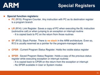
1. ARM started as a replacement for the 8-bit 6502 chip in 1985 and was later spun off as its own company focusing on embedded CPU cores.
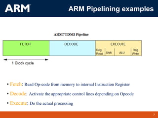
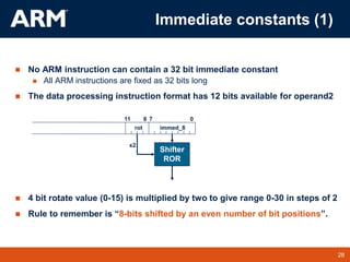
2. ARM is a 32-bit architecture with a load/store design using 3-operand instructions. It has a large register set and pipelined execution, along with some CISC features like complex multiply and load/store instructions.
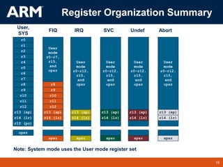
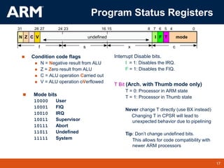
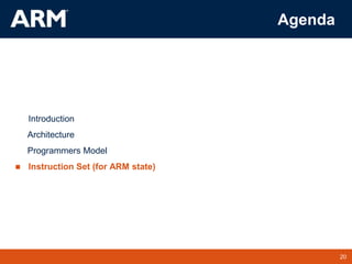
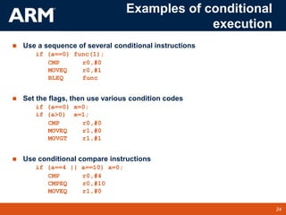
3. The ARM programming model includes 7 processor modes, 37 registers including general purpose and special registers like the program counter and status registers, and conditional execution of instructions.

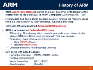
![Address Register
REGISTER
BANK
PC
Address
Incrementer
SHIFT
Multiplier
Write Data Reg.
translator
D[31:0]
INSTRUCCTION
DECODER
Control
Lines
ARM
Thumb to
Instruction Reg.
Read Data Reg.
B
bus
A
bus
ALU
bus
PC
bus
A[31:0]
A.L.U.
ARM7TDMI
Block Diagram](https://image.slidesharecdn.com/mcesunit12arm-instruction-set2023-230828153540-415fb24d/85/LPC-2148-Instructions-Set-ppt-6-320.jpg)
![18
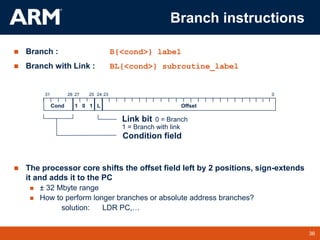
TM 18
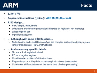
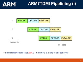
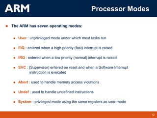
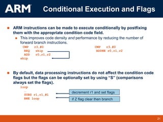
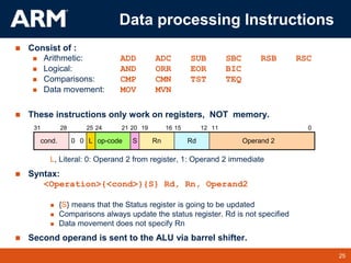
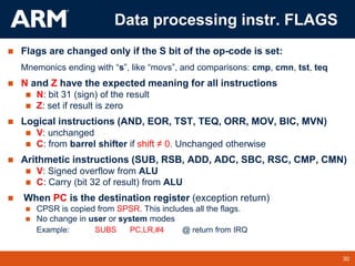
When the processor is executing in ARM state:
All instructions are 32 bits wide
All instructions must be word aligned
Therefore the PC value is stored in bits [31:2] and bits [1:0] are zero
Due to pipelining, the PC points 8 bytes ahead of the current instruction, or 12
bytes ahead if current instruction includes a register-specified shift
When the processor is executing in Thumb state:
All instructions are 16 bits wide
All instructions must be halfword aligned
Therefore the PC value is stored in bits [31:1] and bit [0] is zero
Program Counter (R15)](https://image.slidesharecdn.com/mcesunit12arm-instruction-set2023-230828153540-415fb24d/85/LPC-2148-Instructions-Set-ppt-18-320.jpg)
![29
TM 29
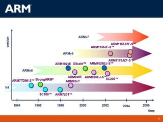
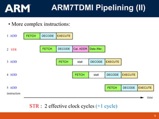
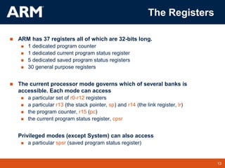
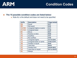
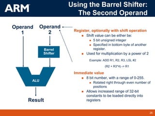
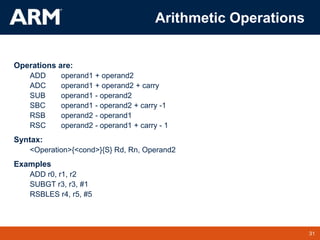
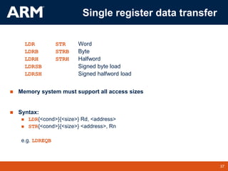
To allow larger constants to be loaded, the assembler offers a pseudo-
instruction:
LDR rd, =const (notice the “=“ sign)
This will either:
Produce a MOV or MVN instruction to generate the value (if possible).
or
Generate a LDR instruction with a PC-relative address to read the constant
from a literal pool (Constant data area embedded in the code).
For example
LDR r0,=0xFF => MOV r0,#0xFF
LDR r0,=0x55555555 => LDR r0,[PC,#Imm12]
…
…
DCD 0x55555555
This is the recommended way of loading constants into a register
Loading 32 bit constants](https://image.slidesharecdn.com/mcesunit12arm-instruction-set2023-230828153540-415fb24d/85/LPC-2148-Instructions-Set-ppt-29-320.jpg)
![33
TM 33
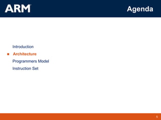
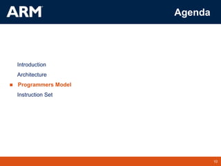
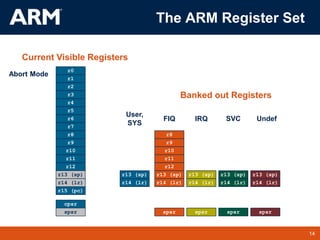
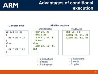
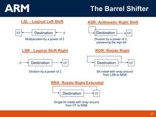
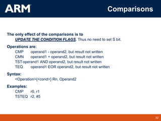
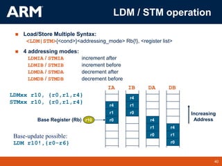
Logical Operations
Operations are:
AND operand1 AND operand2
EOR operand1 EOR operand2
ORR operand1 OR operand2
BIC operand1 AND NOT operand2 [ie bit clear]
Syntax:
<Operation>{<cond>}{S} Rd, Rn, Operand2
Examples:
AND r0, r1, r2
BICEQ r2, r3, #7
EORS r1,r3,r0](https://image.slidesharecdn.com/mcesunit12arm-instruction-set2023-230828153540-415fb24d/85/LPC-2148-Instructions-Set-ppt-33-320.jpg)
![35
TM 35
Multiply
Syntax:
MUL{<cond>}{S} Rd, Rm, Rs Rd = Rm * Rs
MLA{<cond>}{S} Rd,Rm,Rs,Rn Rd = (Rm * Rs) + Rn
[U|S]MULL{<cond>}{S} RdLo, RdHi, Rm, Rs RdHi,RdLo := Rm*Rs
[U|S]MLAL{<cond>}{S} RdLo, RdHi, Rm, Rs RdHi,RdLo:=(Rm*Rs)+RdHi,RdLo
Cycle time
Basic MUL instruction
2-5 cycles on ARM7TDMI
1-3 cycles on StrongARM/XScale
2 cycles on ARM9E/ARM102xE
+1 cycle for ARM9TDMI (over ARM7TDMI)
+1 cycle for accumulate (not on 9E though result delay is one cycle longer)
+1 cycle for “long”
Above are “general rules” - refer to the TRM for the core you are using
for the exact details](https://image.slidesharecdn.com/mcesunit12arm-instruction-set2023-230828153540-415fb24d/85/LPC-2148-Instructions-Set-ppt-35-320.jpg)
![38
TM 38
Address accessed
Address accessed by LDR/STR is specified by a base register plus an
offset
For word and unsigned byte accesses, offset can be
An unsigned 12-bit immediate value (ie 0 - 4095 bytes).
LDR r0,[r1,#8]
A register, optionally shifted by an immediate value
LDR r0,[r1,r2]
LDR r0,[r1,r2,LSL#2]
This can be either added or subtracted from the base register:
LDR r0,[r1,#-8]
LDR r0,[r1,-r2]
LDR r0,[r1,-r2,LSL#2]
For halfword and signed halfword / byte, offset can be:
An unsigned 8 bit immediate value (ie 0-255 bytes).
A register (unshifted).
Choice of pre-indexed or post-indexed addressing](https://image.slidesharecdn.com/mcesunit12arm-instruction-set2023-230828153540-415fb24d/85/LPC-2148-Instructions-Set-ppt-38-320.jpg)
![39
TM 39
0x5
0x5
r1
0x200
Base
Register 0x200
r0
0x5
Source
Register
for STR
Offset
12 0x20c
r1
0x200
Original
Base
Register
0x200
r0
0x5
Source
Register
for STR
Offset
12 0x20c
r1
0x20c
Updated
Base
Register
Base-update form (‘!’): STR r0,[r1,#12]!
Pre or Post Indexed Addressing?
Pre-indexed: STR r0,[r1,#12]
Post-indexed: STR r0,[r1],#12
Base register always updated](https://image.slidesharecdn.com/mcesunit12arm-instruction-set2023-230828153540-415fb24d/85/LPC-2148-Instructions-Set-ppt-39-320.jpg)
![41
TM 41
Atomic data swap
Exchanges a word or byte between a register and a
memory location
This operation cannot be interrupted, not even by DMA
Main use: Operating System semaphores
Syntax:
SWP {<cond>} Rd, Rm, [Rn]
SWPB{<cond>} Rd, Rm, [Rn]
Rd=[Rn]; [Rn]=Rm (Rd and Rm can be the same)](https://image.slidesharecdn.com/mcesunit12arm-instruction-set2023-230828153540-415fb24d/85/LPC-2148-Instructions-Set-ppt-41-320.jpg)