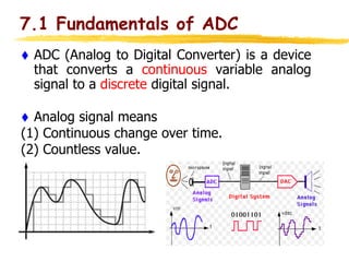
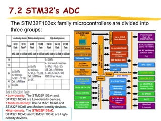
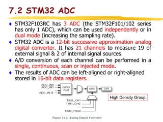
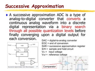
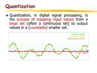
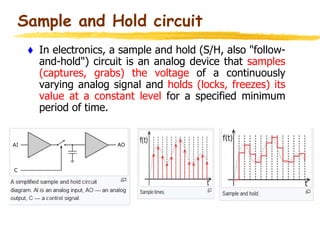
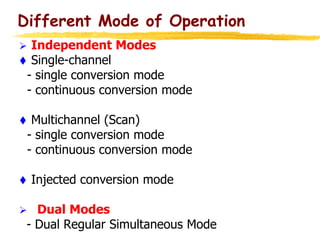
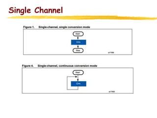
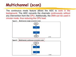
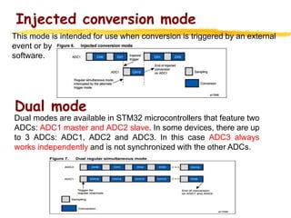
STM32’s ADC
Md Rayhan Tanvir
Directory
The main content of this topic:
 7.1 ADC Fundamentals
 7.2 STM32’s ADC
Introduction
Electric vehicle speed control system, how does this speed value come from?
Continue
7.1 Fundamentals of ADC
 ADC (Analog to Digital Converter) is a device
that converts a continuous variable analog
signal to a discrete digital signal.
 Analog signal means
(1) Continuous change over time.
(2) Countless value.
Applications
•Audio
 – Speech recognition
 – Special effects (reverb, noise cancellation etc)
•Video
 – Filtering
 – Special effects
 – Compression
•Data logging
A data logger (also datalogger or data recorder) is an electronic device that
records data over time or in relation to location either with a built in
instrument or sensor or via external instruments and sensors.
7.2 STM32’s ADC
The STM32F103xx family microcontrollers are divided into
three groups:
 Low-density: The STM32F103x4 and
STM32F103x6 are Low-density devices.
 Medium-density: The STM32F103x8 and
STM32F103xB are Medium-density devices.
High-density: The STM32F103xC,
STM32F103xD and STM32F103xE are High-
density devices.
7.2 STM32’s ADC
7.2 STM32 ADC
 STM32F103RC has 3 ADC (the STM32F101/102 series
has only 1 ADC), which can be used independently or in
dual mode (increasing the sampling rate).
 STM32 ADC is a 12-bit successive approximation analog
digital converter. It has 21 channels to measure 19 of
external signal & 2 of internal signal sources.
 A/D conversion of each channel can be performed in a
single, continuous, scan or injected mode.
 The results of ADC can be left-aligned or right-aligned
stored in 16-bit data registers.
High Density Group
Successive Approximation
 A successive approximation ADC is a type of
analog-to-digital converter that converts a
continuous analog waveform into a discrete
digital representation via a binary search
through all possible quantization levels before
finally converging upon a digital output for
each conversion. DAC = digital-to-analog converter
EOC = end of conversion
SAR = successive approximation register
S/H = sample and hold circuit
Vin = input voltage
Vref = reference voltage
Comparator
Quantization
 Quantization, in digital signal processing, is
the process of mapping input values from a
large set (often a continuous set) to output
values in a (countable) smaller set.
Sample and Hold circuit
 In electronics, a sample and hold (S/H, also "follow-
and-hold") circuit is an analog device that samples
(captures, grabs) the voltage of a continuously
varying analog signal and holds (locks, freezes) its
value at a constant level for a specified minimum
period of time.
Different Mode of Operation
 Independent Modes
 Single-channel
- single conversion mode
- continuous conversion mode
 Multichannel (Scan)
- single conversion mode
- continuous conversion mode
 Injected conversion mode
 Dual Modes
- Dual Regular Simultaneous Mode
Single Channel
Multichannel (scan)
The continuous mode feature allows the ADC to work in the
background. The ADC converts the channels continuously without
any intervention from the CPU. Additionally, the DMA can be used in
circular mode, thus reducing the CPU load.
Injected conversion mode
Dual mode
Dual modes are available in STM32 microcontrollers that feature two
ADCs: ADC1 master and ADC2 slave. In some devices, there are up
to 3 ADCs: ADC1, ADC2 and ADC3. In this case ADC3 always
works independently and is not synchronized with the other ADCs.
This mode is intended for use when conversion is triggered by an external
event or by
software.
3 STM32's ADC.ppt

3 STM32's ADC.ppt

  • 1.
  • 2.
    Directory The main contentof this topic:  7.1 ADC Fundamentals  7.2 STM32’s ADC
  • 3.
    Introduction Electric vehicle speedcontrol system, how does this speed value come from?
  • 4.
  • 5.
    7.1 Fundamentals ofADC  ADC (Analog to Digital Converter) is a device that converts a continuous variable analog signal to a discrete digital signal.  Analog signal means (1) Continuous change over time. (2) Countless value.
  • 6.
    Applications •Audio  – Speechrecognition  – Special effects (reverb, noise cancellation etc) •Video  – Filtering  – Special effects  – Compression •Data logging A data logger (also datalogger or data recorder) is an electronic device that records data over time or in relation to location either with a built in instrument or sensor or via external instruments and sensors.
  • 7.
    7.2 STM32’s ADC TheSTM32F103xx family microcontrollers are divided into three groups:  Low-density: The STM32F103x4 and STM32F103x6 are Low-density devices.  Medium-density: The STM32F103x8 and STM32F103xB are Medium-density devices. High-density: The STM32F103xC, STM32F103xD and STM32F103xE are High- density devices.
  • 8.
  • 9.
    7.2 STM32 ADC STM32F103RC has 3 ADC (the STM32F101/102 series has only 1 ADC), which can be used independently or in dual mode (increasing the sampling rate).  STM32 ADC is a 12-bit successive approximation analog digital converter. It has 21 channels to measure 19 of external signal & 2 of internal signal sources.  A/D conversion of each channel can be performed in a single, continuous, scan or injected mode.  The results of ADC can be left-aligned or right-aligned stored in 16-bit data registers. High Density Group
  • 10.
    Successive Approximation  Asuccessive approximation ADC is a type of analog-to-digital converter that converts a continuous analog waveform into a discrete digital representation via a binary search through all possible quantization levels before finally converging upon a digital output for each conversion. DAC = digital-to-analog converter EOC = end of conversion SAR = successive approximation register S/H = sample and hold circuit Vin = input voltage Vref = reference voltage Comparator
  • 11.
    Quantization  Quantization, indigital signal processing, is the process of mapping input values from a large set (often a continuous set) to output values in a (countable) smaller set.
  • 12.
    Sample and Holdcircuit  In electronics, a sample and hold (S/H, also "follow- and-hold") circuit is an analog device that samples (captures, grabs) the voltage of a continuously varying analog signal and holds (locks, freezes) its value at a constant level for a specified minimum period of time.
  • 13.
    Different Mode ofOperation  Independent Modes  Single-channel - single conversion mode - continuous conversion mode  Multichannel (Scan) - single conversion mode - continuous conversion mode  Injected conversion mode  Dual Modes - Dual Regular Simultaneous Mode
  • 14.
  • 15.
    Multichannel (scan) The continuousmode feature allows the ADC to work in the background. The ADC converts the channels continuously without any intervention from the CPU. Additionally, the DMA can be used in circular mode, thus reducing the CPU load.
  • 16.
    Injected conversion mode Dualmode Dual modes are available in STM32 microcontrollers that feature two ADCs: ADC1 master and ADC2 slave. In some devices, there are up to 3 ADCs: ADC1, ADC2 and ADC3. In this case ADC3 always works independently and is not synchronized with the other ADCs. This mode is intended for use when conversion is triggered by an external event or by software.

Editor's Notes

  • #4 Sensors in the sensing of the gas, the internal sensitive elements of the resistance will change, resulting in a change in the size of the output voltage. If your application is to measure the concentration of the detected gas, it must go through A/D conversion.