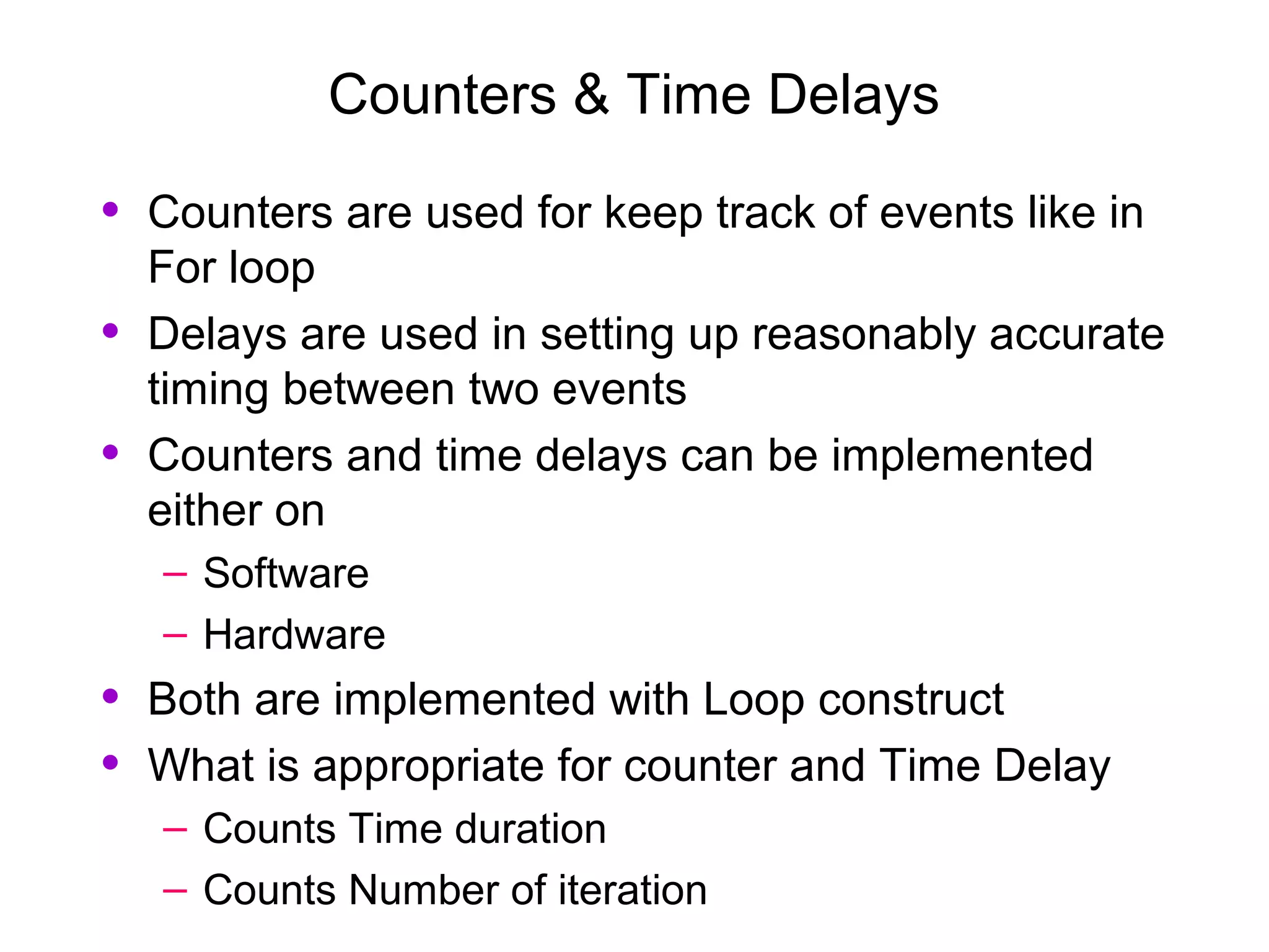
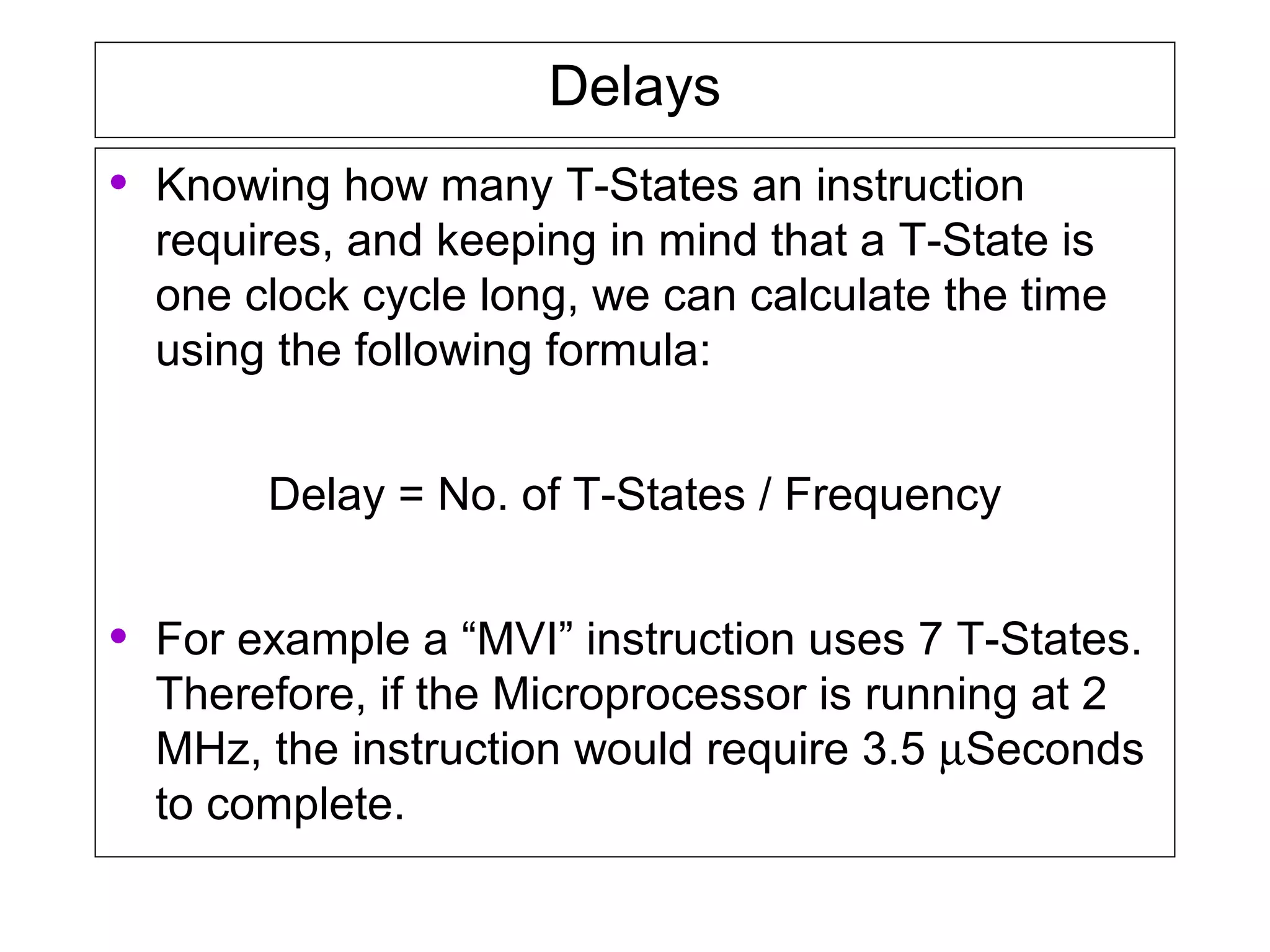
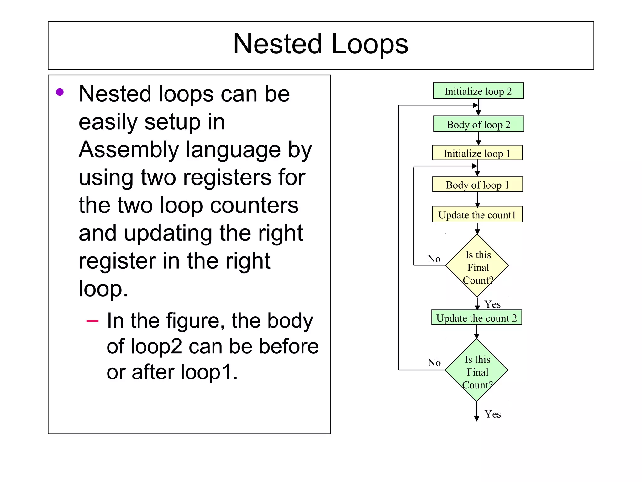
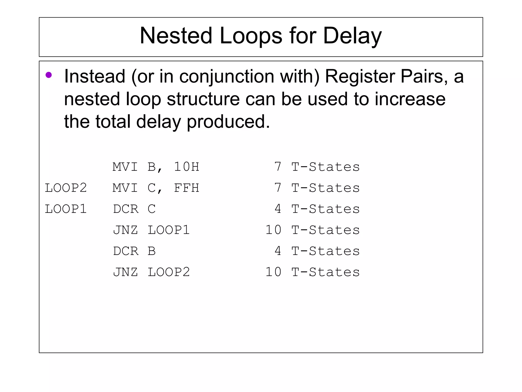
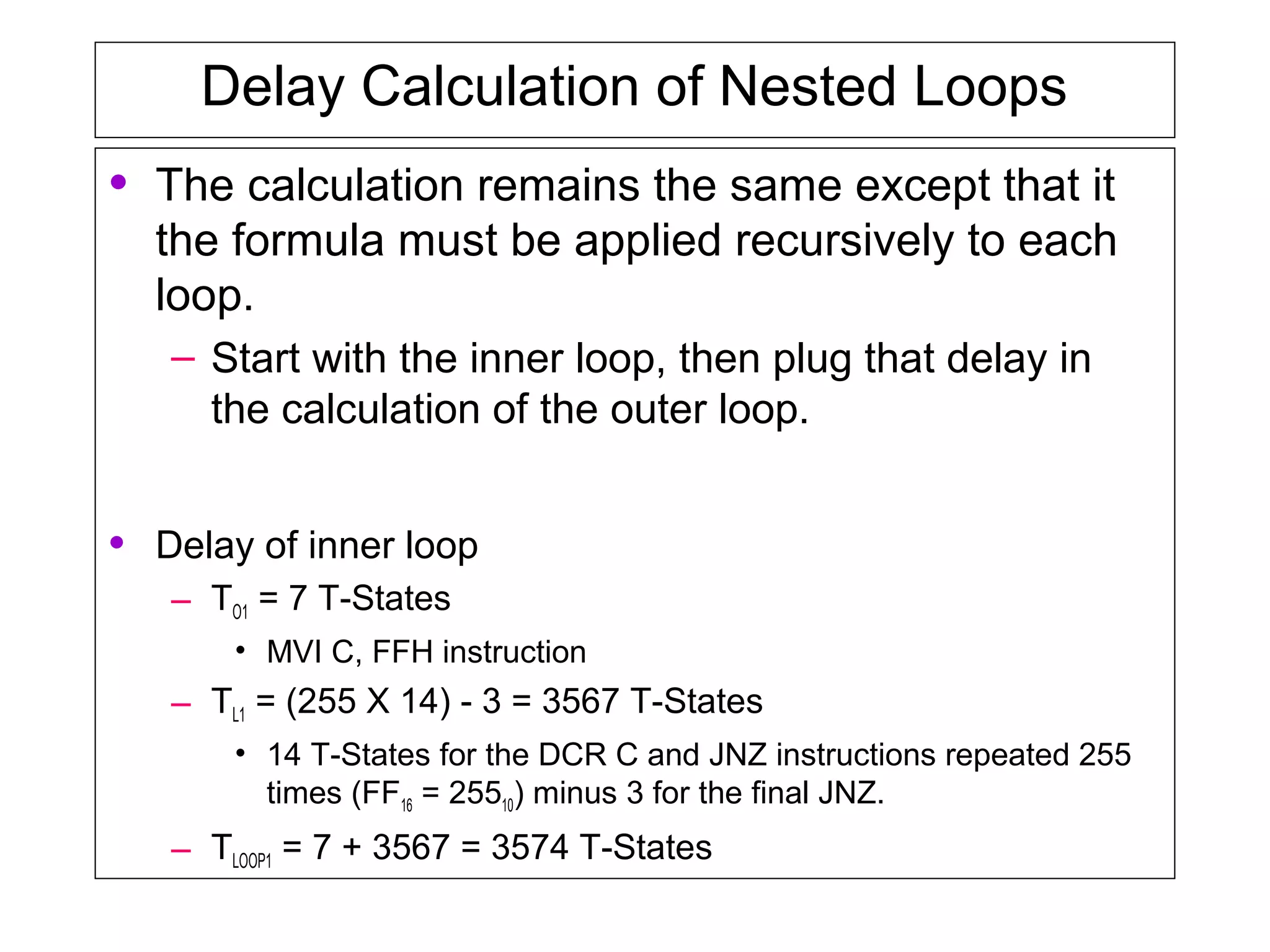
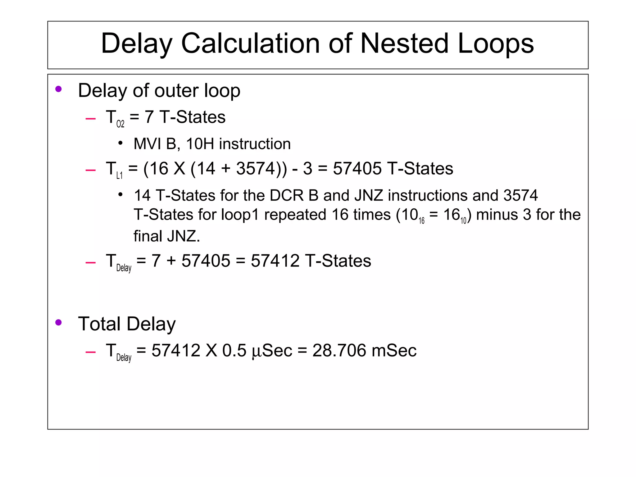
Counters and time delays can be implemented in software or hardware using loop constructs. Counters keep track of events like iterations in a for loop, while delays set up accurate timing between events. Delays can be implemented using loops that iterate a set number of times based on instruction timing. Nested loops and register pairs can increase delay times for longer periods.
The microprocessor is the core of computer systems.
Nowadays many communication, digital entertainment, portable devices, are controlled by them.
A designer should know what types of components he needs, ways to reduce production costs and product reliable.
This presentation discusses the support for interrupts in 8051. The interrupt types, interrupts versus polling etc are discussed. The register formats of IE, IP register are discussed. The concept of priority among the interrupts is discussed.
Time delays & counter, Need of Counter and Time Delays, Using a Register Pair as a Counter, Delay Loops, Using a Register Pair as a Loop Counter, Delay Calculation of Nested Loops, Increasing the delay.
Semiconductor Memory Fundamentals
Memory Types
Memory Structure and its requirements
Memory Decoding
Examples
Input - Output Interfacing
Types of Parallel Data Transfer or I/O Techniques
Addressing mode and instruction set using 8051logesh waran
1. Immediate addressing mode:
In this type, the operand is specified in the instruction along with the opcode. In simple way, it means data is provided in instruction itself.
Ex: MOV A,#05H -> Where MOV stands for move, # represents immediate data. 05h is the data. It means the immediate date 05h provided in instruction is moved into A register.
2.Register addressing mode:
Here the operand in contained in the specific register of microcontroller. The user must provide the name of register from where the operand/data need to be fetched. The permitted registers are A, R7-R0 of each register bank. Ex: MOV A,R0-> content of R0 register is copied into Accumulator.
3. Direct addressing mode:
In this mode the direct address of memory location is provided in instruction to fetch the operand. Only internal RAM and SFR's address can be used in this type of instruction.
Ex: MOV A, 30H => Content of RAM address 30H is copied into Accumulator.
4. Register Indirect addressing mode:
Here the address of memory location is indirectly provided by a register. The '@' sign indicates that the register holds the address of memory location i.e. fetch the content of memory location whose address is provided in register.
Ex: MOV A,@R0 => Copy the content of memory location whose address is given in R0 register.
5. Indexed Addressing mode:
This addressing mode is basically used for accessing data from look up table. Here the address of memory is indexed i.e. added to form the actual address of memory.
Ex: MOVC A,@A+DPTR => here 'C' means Code. Here the content of A register is added with content of DPTR and the resultant is the address of memory location from where the data is copied to A register.
Overview of the fundamental roles in Hydropower generation and the components involved in wider Electrical Engineering.
This paper presents the design and construction of hydroelectric dams from the hydrologist’s survey of the valley before construction, all aspects and involved disciplines, fluid dynamics, structural engineering, generation and mains frequency regulation to the very transmission of power through the network in the United Kingdom.
Author: Robbie Edward Sayers
Collaborators and co editors: Charlie Sims and Connor Healey.
(C) 2024 Robbie E. Sayers
Immunizing Image Classifiers Against Localized Adversary Attacksgerogepatton
This paper addresses the vulnerability of deep learning models, particularly convolutional neural networks
(CNN)s, to adversarial attacks and presents a proactive training technique designed to counter them. We
introduce a novel volumization algorithm, which transforms 2D images into 3D volumetric representations.
When combined with 3D convolution and deep curriculum learning optimization (CLO), itsignificantly improves
the immunity of models against localized universal attacks by up to 40%. We evaluate our proposed approach
using contemporary CNN architectures and the modified Canadian Institute for Advanced Research (CIFAR-10
and CIFAR-100) and ImageNet Large Scale Visual Recognition Challenge (ILSVRC12) datasets, showcasing
accuracy improvements over previous techniques. The results indicate that the combination of the volumetric
input and curriculum learning holds significant promise for mitigating adversarial attacks without necessitating
adversary training.
Explore the innovative world of trenchless pipe repair with our comprehensive guide, "The Benefits and Techniques of Trenchless Pipe Repair." This document delves into the modern methods of repairing underground pipes without the need for extensive excavation, highlighting the numerous advantages and the latest techniques used in the industry.
Learn about the cost savings, reduced environmental impact, and minimal disruption associated with trenchless technology. Discover detailed explanations of popular techniques such as pipe bursting, cured-in-place pipe (CIPP) lining, and directional drilling. Understand how these methods can be applied to various types of infrastructure, from residential plumbing to large-scale municipal systems.
Ideal for homeowners, contractors, engineers, and anyone interested in modern plumbing solutions, this guide provides valuable insights into why trenchless pipe repair is becoming the preferred choice for pipe rehabilitation. Stay informed about the latest advancements and best practices in the field.
Student information management system project report ii.pdfKamal Acharya
Our project explains about the student management. This project mainly explains the various actions related to student details. This project shows some ease in adding, editing and deleting the student details. It also provides a less time consuming process for viewing, adding, editing and deleting the marks of the students.
About
Indigenized remote control interface card suitable for MAFI system CCR equipment. Compatible for IDM8000 CCR. Backplane mounted serial and TCP/Ethernet communication module for CCR remote access. IDM 8000 CCR remote control on serial and TCP protocol.
• Remote control: Parallel or serial interface.
• Compatible with MAFI CCR system.
• Compatible with IDM8000 CCR.
• Compatible with Backplane mount serial communication.
• Compatible with commercial and Defence aviation CCR system.
• Remote control system for accessing CCR and allied system over serial or TCP.
• Indigenized local Support/presence in India.
• Easy in configuration using DIP switches.
Technical Specifications
Indigenized remote control interface card suitable for MAFI system CCR equipment. Compatible for IDM8000 CCR. Backplane mounted serial and TCP/Ethernet communication module for CCR remote access. IDM 8000 CCR remote control on serial and TCP protocol.
Key Features
Indigenized remote control interface card suitable for MAFI system CCR equipment. Compatible for IDM8000 CCR. Backplane mounted serial and TCP/Ethernet communication module for CCR remote access. IDM 8000 CCR remote control on serial and TCP protocol.
• Remote control: Parallel or serial interface
• Compatible with MAFI CCR system
• Copatiable with IDM8000 CCR
• Compatible with Backplane mount serial communication.
• Compatible with commercial and Defence aviation CCR system.
• Remote control system for accessing CCR and allied system over serial or TCP.
• Indigenized local Support/presence in India.
Application
• Remote control: Parallel or serial interface.
• Compatible with MAFI CCR system.
• Compatible with IDM8000 CCR.
• Compatible with Backplane mount serial communication.
• Compatible with commercial and Defence aviation CCR system.
• Remote control system for accessing CCR and allied system over serial or TCP.
• Indigenized local Support/presence in India.
• Easy in configuration using DIP switches.
Water scarcity is the lack of fresh water resources to meet the standard water demand. There are two type of water scarcity. One is physical. The other is economic water scarcity.
CFD Simulation of By-pass Flow in a HRSG module by R&R Consult.pptxR&R Consult
CFD analysis is incredibly effective at solving mysteries and improving the performance of complex systems!
Here's a great example: At a large natural gas-fired power plant, where they use waste heat to generate steam and energy, they were puzzled that their boiler wasn't producing as much steam as expected.
R&R and Tetra Engineering Group Inc. were asked to solve the issue with reduced steam production.
An inspection had shown that a significant amount of hot flue gas was bypassing the boiler tubes, where the heat was supposed to be transferred.
R&R Consult conducted a CFD analysis, which revealed that 6.3% of the flue gas was bypassing the boiler tubes without transferring heat. The analysis also showed that the flue gas was instead being directed along the sides of the boiler and between the modules that were supposed to capture the heat. This was the cause of the reduced performance.
Based on our results, Tetra Engineering installed covering plates to reduce the bypass flow. This improved the boiler's performance and increased electricity production.
It is always satisfying when we can help solve complex challenges like this. Do your systems also need a check-up or optimization? Give us a call!
Work done in cooperation with James Malloy and David Moelling from Tetra Engineering.
More examples of our work https://www.r-r-consult.dk/en/cases-en/
2. Counters & Time Delays
• Counters are used for keep track of events like in
For loop
• Delays are used in setting up reasonably accurate
timing between two events
• Counters and time delays can be implemented
either on
– Software
– Hardware
• Both are implemented with Loop construct
• What is appropriate for counter and Time Delay
– Counts Time duration
– Counts Number of iteration
3. Counters
• A loop counter is set up by loading a register with
a certain value
• Then using the DCR (to decrement) and INR (to
increment) the contents of the register are
updated.
• A loop is set up with a conditional jump
instruction that loops back or not depending on
whether the count has reached the termination
count.
4. Counters
• The operation of a loop counter can be described
using the following flowchart.
Initialize
Update the count
Is this
Final
Count?
Body of loop
No
Yes
5. Delays
• It was shown in Chapter 2 that each instruction
passes through different combinations of Fetch,
Memory Read, and Memory Write cycles.
• Knowing the combinations of cycles, one can
calculate how long such an instruction would
require to complete.
• The table in Appendix F of the book contains a
column with the title B/M/T.
– B for Number of Bytes
– M for Number of Machine Cycles
– T for Number of T-State.
6. Delays
• Knowing how many T-States an instruction
requires, and keeping in mind that a T-State is
one clock cycle long, we can calculate the time
using the following formula:
Delay = No. of T-States / Frequency
• For example a “MVI” instruction uses 7 T-States.
Therefore, if the Microprocessor is running at 2
MHz, the instruction would require 3.5 µSeconds
to complete.
7. Delay loops
• We can use a loop to produce a certain amount
of time delay in a program.
• The following is an example of a delay loop:
MVI C, FFH 7 T-States
LOOP DCR C 4 T-States
JNZ LOOP 10 T-States
• The first instruction initializes the loop counter and is executed
only once requiring only 7 T-States.
• The following two instructions form a loop that requires 14 T-
States to execute and is repeated 255 times until C becomes 0.
8. Delay Loops (Contd.)
• We need to keep in mind though that in the last iteration of the
loop, the JNZ instruction will fail and require only 7 T-States
rather than the 10.
• Therefore, we must deduct 3 T-States from the total delay to get
an accurate delay calculation.
• To calculate the delay, we use the following formula:
Tdelay = TO + TL
– Tdelay = total delay
– TO = delay outside the loop
– TL = delay of the loop
• TO is the sum of all delays outside the loop.
• TL is calculated using the formula
TL = T X Loop T-States X N10
9. Delay Loops (Contd.)
• Using these formulas, we can calculate the time
delay for the previous example:
• TO = 7 T-States
– Delay of the MVI instruction
• TL = (14 X 255) - 3 = 3567 T-States
– 14 T-States for the 2 instructions repeated 255 times
(FF16 = 25510) reduced by the 3 T-States for the final JNZ.
• TDelay = (7 + 3567) X 0.5 µSec = 1.787 mSec
– Assuming f = 2 MHz
10. Using a Register Pair as a Loop Counter
• Using a single register, one can repeat a loop for
a maximum count of 255 times.
• It is possible to increase this count by using a
register pair for the loop counter instead of the
single register.
– A minor problem arises in how to test for the final
count since DCX and INX do not modify the flags.
– However, if the loop is looking for when the count
becomes zero, we can use a small trick by ORing
the two registers in the pair and then checking the
zero flag.
11. Using a Register Pair as a Loop Counter
• The following is an example of a delay loop set
up with a register pair as the loop counter.
LXI B, 1000H 10 T-States
LOOP DCX B 6 T-States
MOV A, C 4 T-States
ORA B 4 T-States
JNZ LOOP 10 T-States
12. Using a Register Pair as a Loop Counter
• Using the same formula from before, we can
calculate:
• TO = 10 T-States
– The delay for the LXI instruction
• TL = (24 X 4096) - 3 = 98301 T- States
– 24 T-States for the 4 instructions in the loop repeated
4096 times (100016 = 409610) reduced by the 3 T-States for
the JNZ in the last iteration.
• TDelay = (10 + 98301) X 0.5 mSec = 49.155 mSec
13. Nested Loops
• Nested loops can be
easily setup in
Assembly language by
using two registers for
the two loop counters
and updating the right
register in the right
loop.
– In the figure, the body
of loop2 can be before
or after loop1.
Initialize loop 1
Update the count1
Is this
Final
Count?
Body of loop 1
No
Yes
Initialize loop 2
Body of loop 2
Update the count 2
Is this
Final
Count?
No
Yes
14. Nested Loops for Delay
• Instead (or in conjunction with) Register Pairs, a
nested loop structure can be used to increase
the total delay produced.
MVI B, 10H 7 T-States
LOOP2 MVI C, FFH 7 T-States
LOOP1 DCR C 4 T-States
JNZ LOOP1 10 T-States
DCR B 4 T-States
JNZ LOOP2 10 T-States
15. Delay Calculation of Nested Loops
• The calculation remains the same except that it
the formula must be applied recursively to each
loop.
– Start with the inner loop, then plug that delay in
the calculation of the outer loop.
• Delay of inner loop
– TO1 = 7 T-States
• MVI C, FFH instruction
– TL1 = (255 X 14) - 3 = 3567 T-States
• 14 T-States for the DCR C and JNZ instructions repeated 255
times (FF16 = 25510) minus 3 for the final JNZ.
– TLOOP1 = 7 + 3567 = 3574 T-States
16. Delay Calculation of Nested Loops
• Delay of outer loop
– TO2 = 7 T-States
• MVI B, 10H instruction
– TL1 = (16 X (14 + 3574)) - 3 = 57405 T-States
• 14 T-States for the DCR B and JNZ instructions and 3574
T-States for loop1 repeated 16 times (1016 = 1610) minus 3 for the
final JNZ.
– TDelay = 7 + 57405 = 57412 T-States
• Total Delay
– TDelay = 57412 X 0.5 µSec = 28.706 mSec
17. Increasing the delay
• The delay can be further increased by using
register pairs for each of the loop counters in the
nested loops setup.
• It can also be increased by adding dummy
instructions (like NOP) in the body of the loop.