Downloaded 468 times
![BITE is an acronym for built-in test
equipment.[1] See BIST (Built In Self- Test). The BITE
is characterized primarily as a passive fault
management and diagnosis built into airborne systems
to support the maintenance process. Built-in test
equipment refers to multimeters, oscilloscopes,
discharge probes, and frequency generators that are
provided as part of the system to enable testing and
perform diagnostics.](https://image.slidesharecdn.com/aircraftdigitalcomputersystem-140921203413-phpapp01/85/Aircraft-digital-computer-system-29-320.jpg)


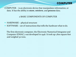
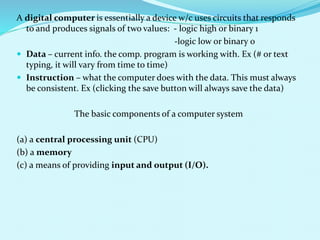
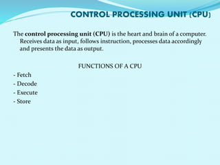
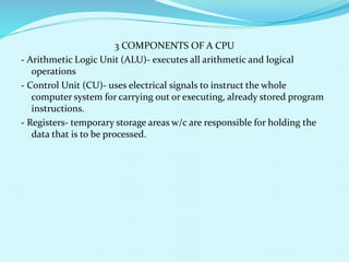
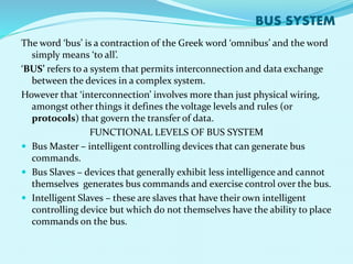
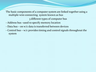
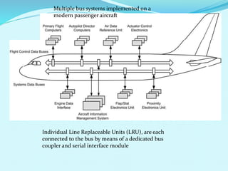
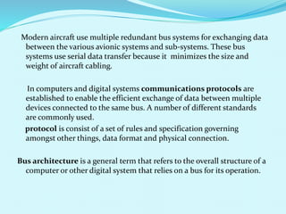
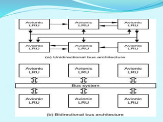
The document discusses digital computer systems used in aircraft. It describes the basic components of a computer including the central processing unit (CPU), memory, and input/output devices. The CPU contains an arithmetic logic unit, control unit, and registers. Data storage includes read-only memory (ROM), random access memory (RAM), and battery-backed memory. Computers systems use bus systems to connect components via address, data, and control buses. Modern aircraft use multiple redundant bus systems and protocols like ARINC 429 for serial data transfer between avionic systems.