is amethod of transmitting information
from one place to another by sending
light through an optical fiber.
The light forms an electromagnetic
carrier wave that is modulated to carry
information.
3.
The process ofcommunicating using fiber-
optics involves the following basic steps:
Creating the optical signal using a
transmitter,
relaying the signal along the fiber,
ensuring that the signal does not become
too distorted or weak,
and receiving the optical signal and
converting it into an electrical signal.
1880 –Alexander Graham Bell
1930 – Patents on tubing
1950 – Patent for two-layer glass wave-guide
1960 – Laser first used as light source
1965 – High loss of light discovered
1970s – Refining of manufacturing process
1980s – OF technology becomes backbone of
long distance telephone networks in NA.
6.
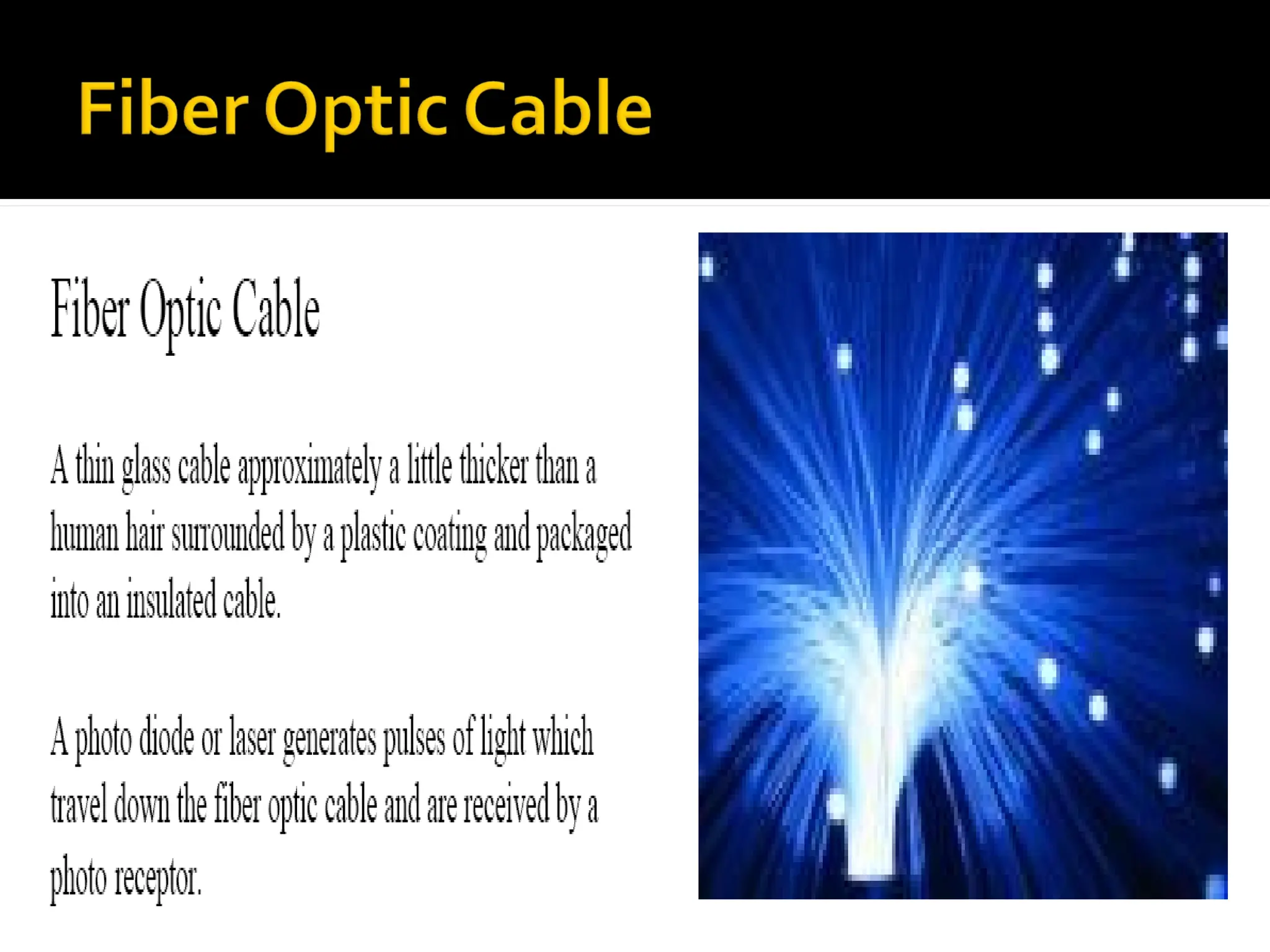
An opticalfiber (or fibre) is a glass or
plastic fiber that carries light along its
length.
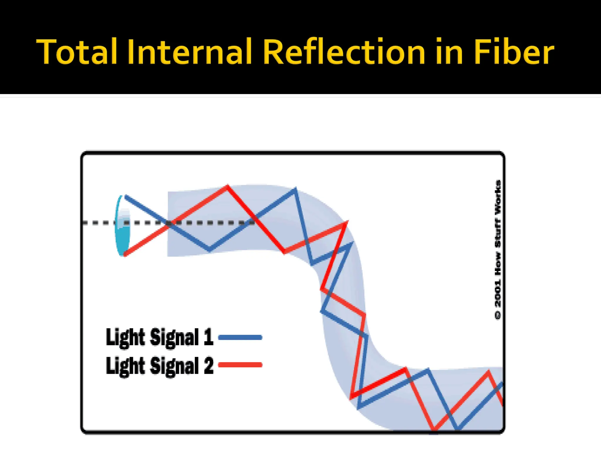
Light is kept in the "core" of the optical
fiber by total internal reflection.
7.
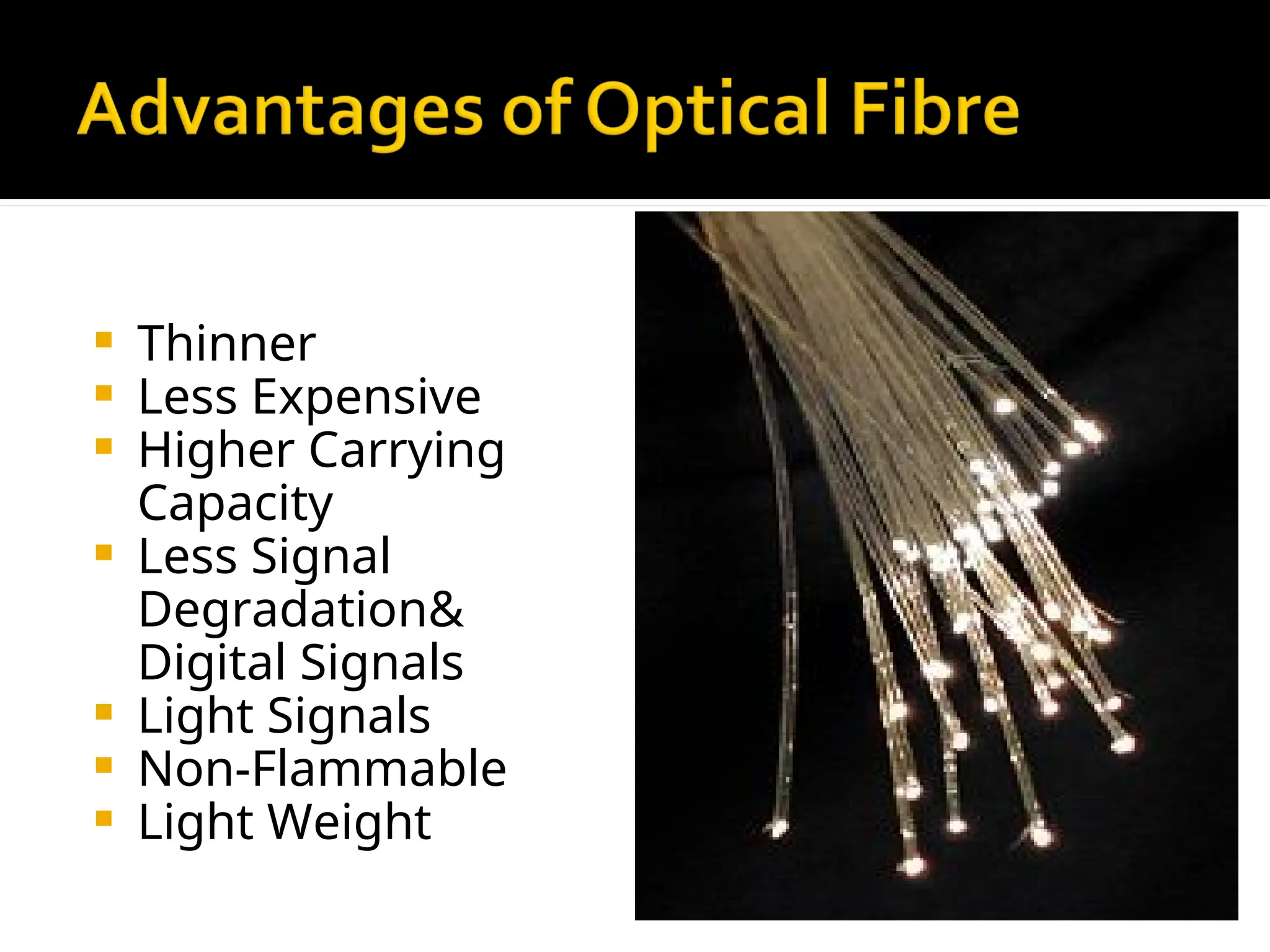
Thinner
LessExpensive
Higher Carrying
Capacity
Less Signal
Degradation&
Digital Signals
Light Signals
Non-Flammable
Light Weight
8.
Much HigherBandwidth (Gbps) -
Thousands of channels can be multiplexed
together over one strand of fiber
Immunity to Noise - Immune to
electromagnetic interference (EMI).
Safety - Doesn’t transmit electrical signals,
making it safe in environments like a gas
pipeline.
High Security - Impossible to “tap into.”
9.
Less Loss- Repeaters can be spaced 75
miles apart (fibers can be made to have
only 0.2 dB/km of attenuation)
Reliability - More resilient than copper in
extreme environmental conditions.
Size - Lighter and more compact than
copper.
Flexibility - Unlike impure, brittle glass,
fiber is physically very flexible.
10.
greater capacity(bandwidth
up to 2 Gbps, or more)
smaller size and lighter
weight
lower attenuation
immunity to environmental
interference
highly secure due to tap
difficulty and lack of signal
radiation
10
11.
Disadvantages
include thecost of
interfacing
equipment necessary
to convert electrical
signals to optical
signals. (optical
transmitters,
receivers) Splicing
fiber optic cable is
also more difficult.
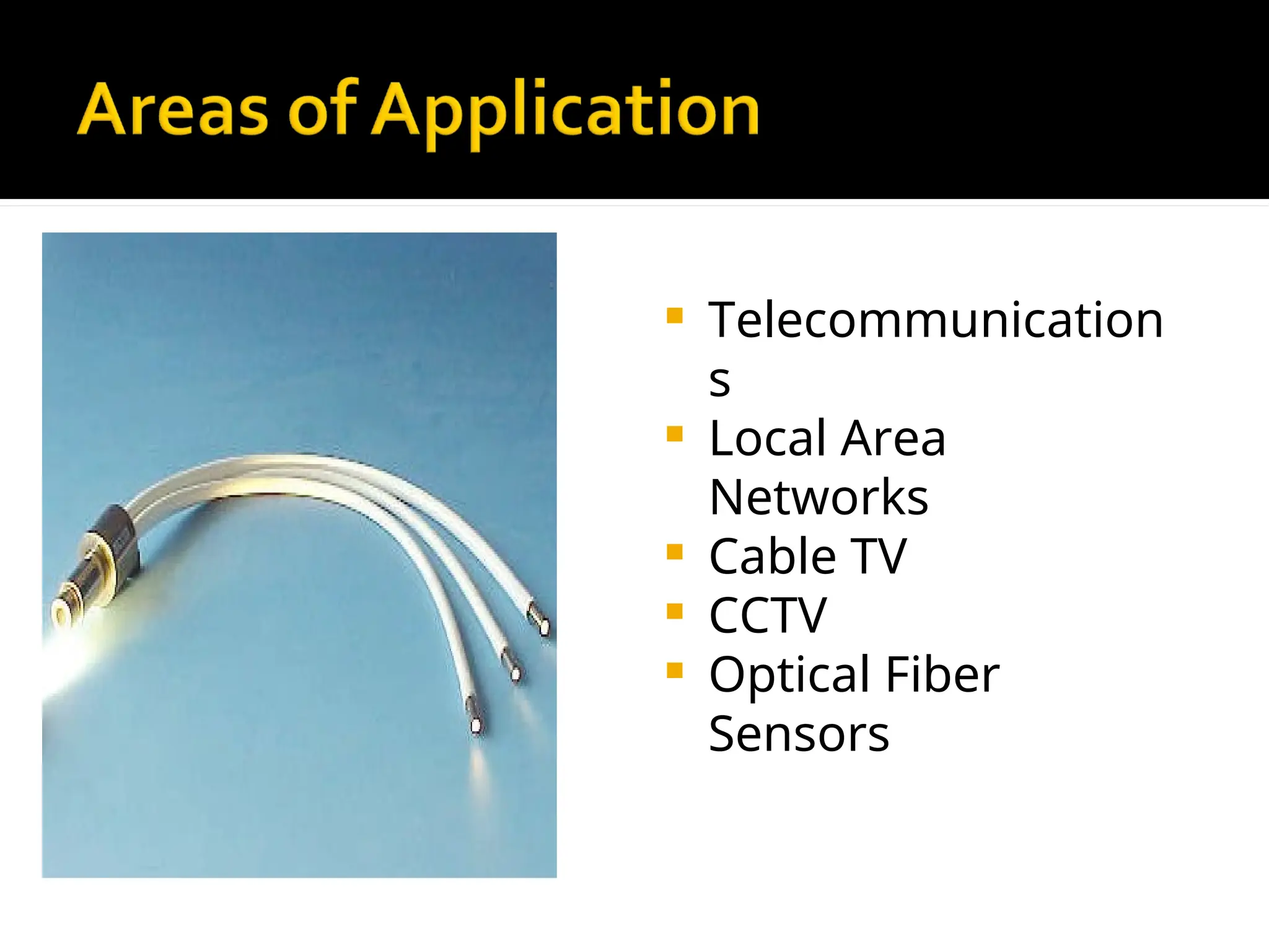
relatively newtransmission medium used by
telephone companies in place of long-distance trunk
lines
also used by private companies in implementing
local data networks
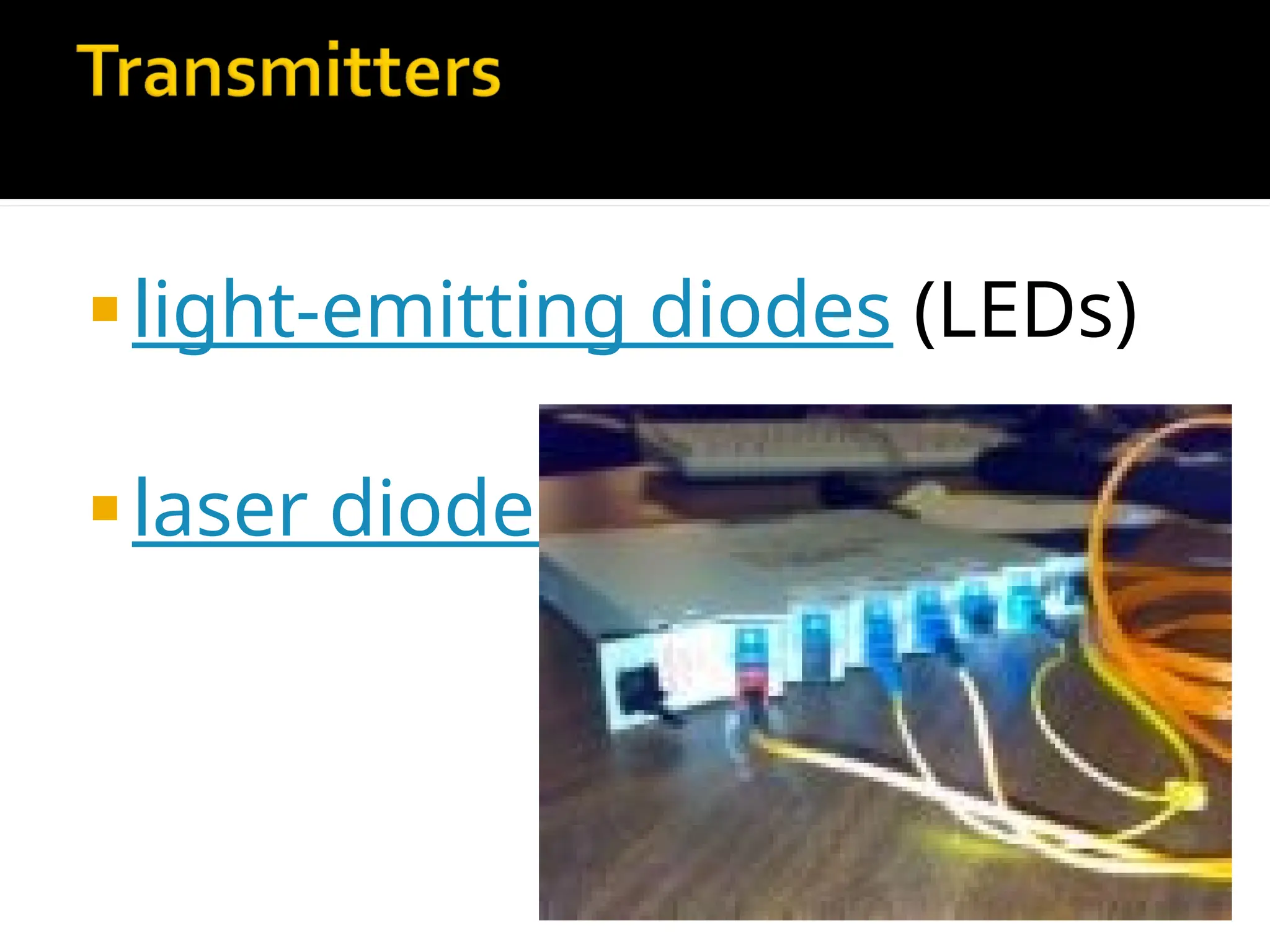
require a light source with injection laser diode (ILD)
or light-emitting diodes (LED)
fiber to the desktop in the future
14
16.
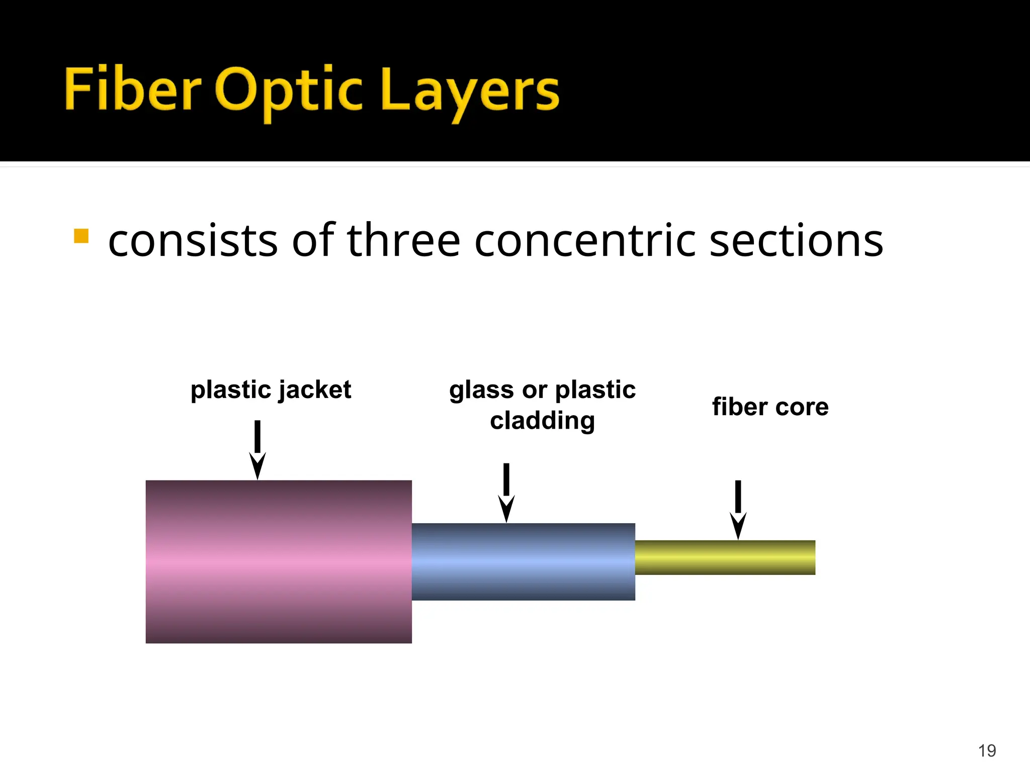
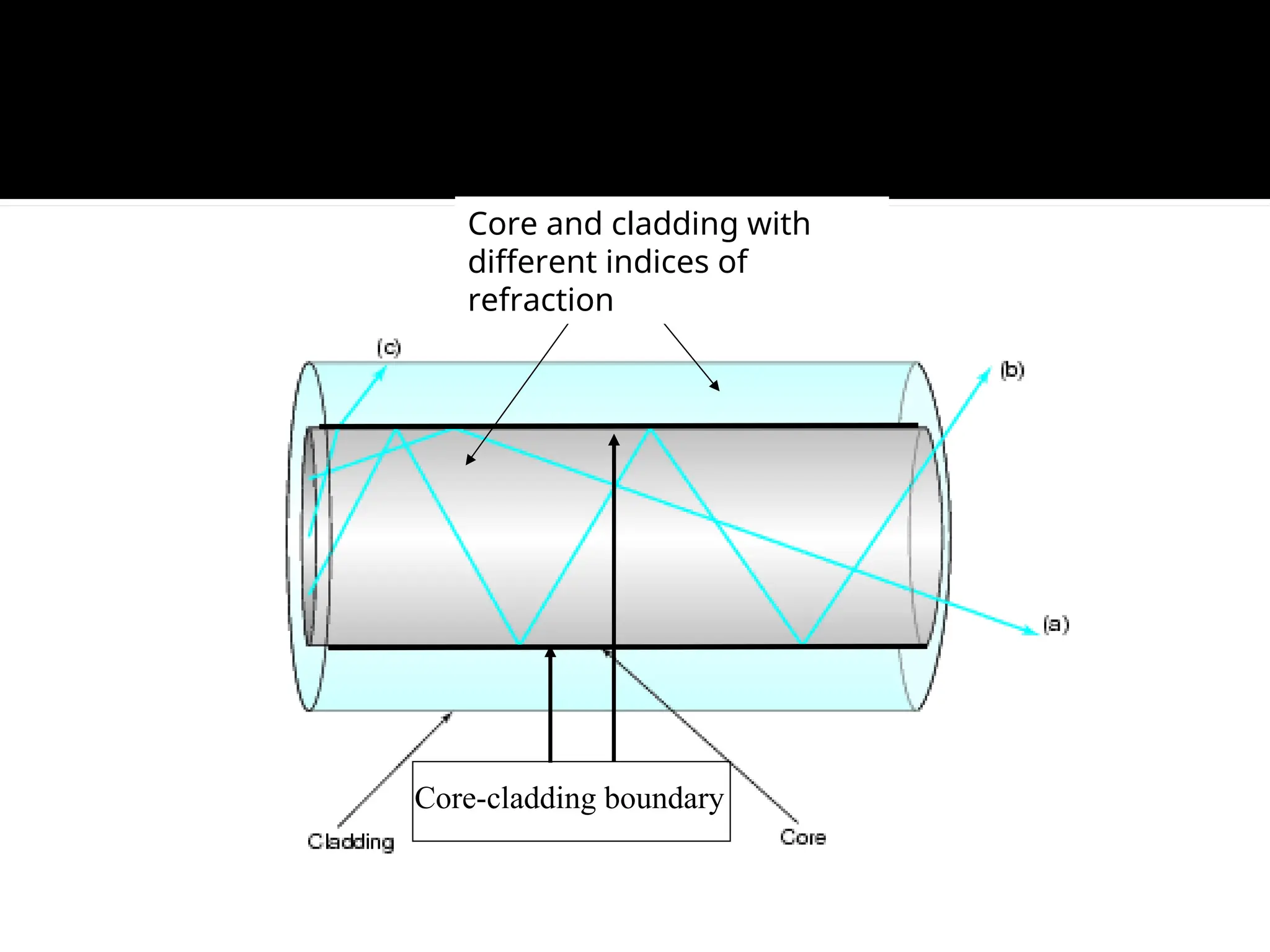
Optical fiberconsists of a core, cladding
, and a protective outer coating, which
guides light along the core by
total internal reflection.
17.
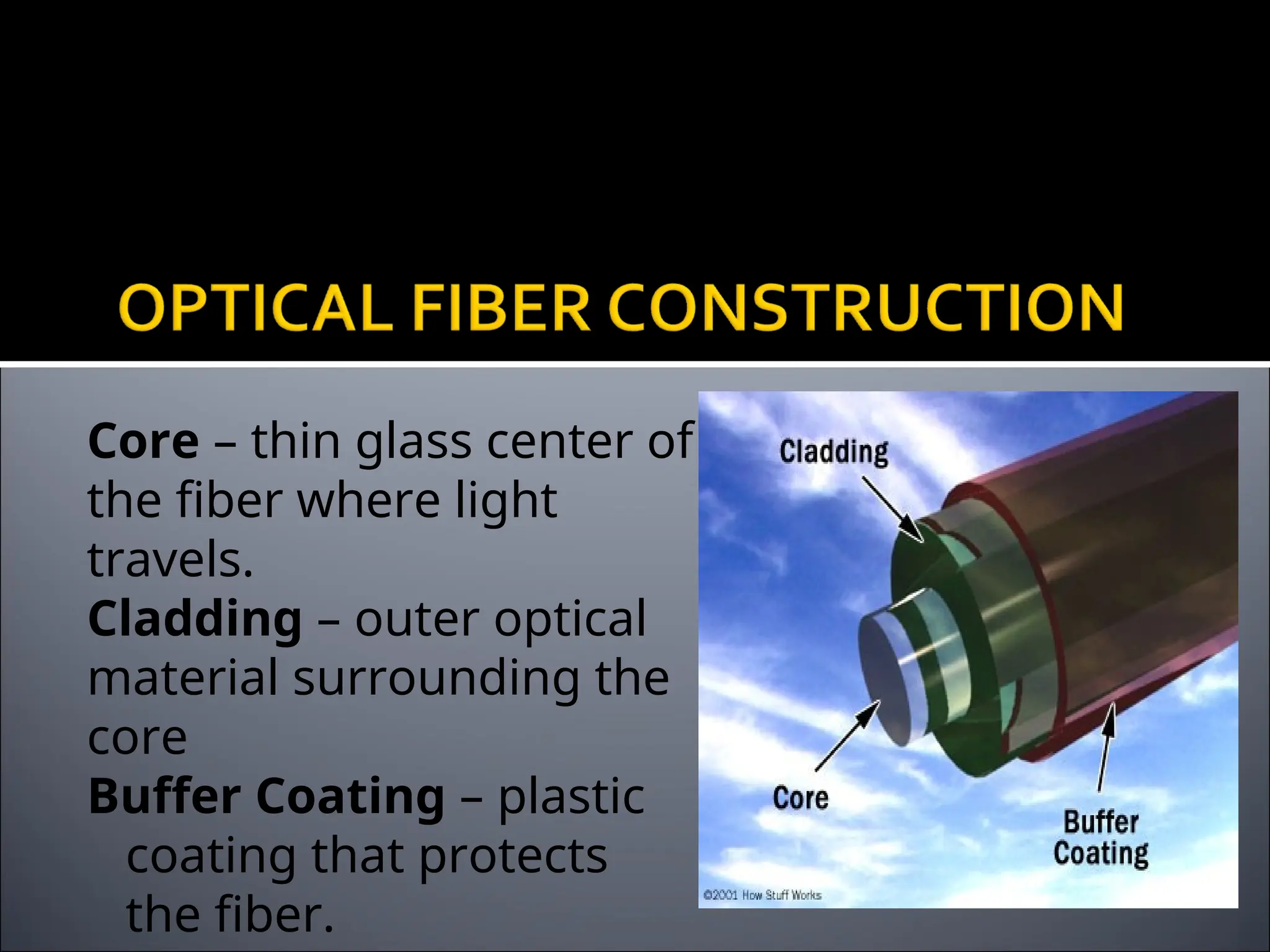
Core – thinglass center of
the fiber where light
travels.
Cladding – outer optical
material surrounding the
core
Buffer Coating – plastic
coating that protects
the fiber.
18.
The core,and the lower-refractive-index
cladding, are typically made of high-
quality silica glass, though they can
both be made of plastic as well.
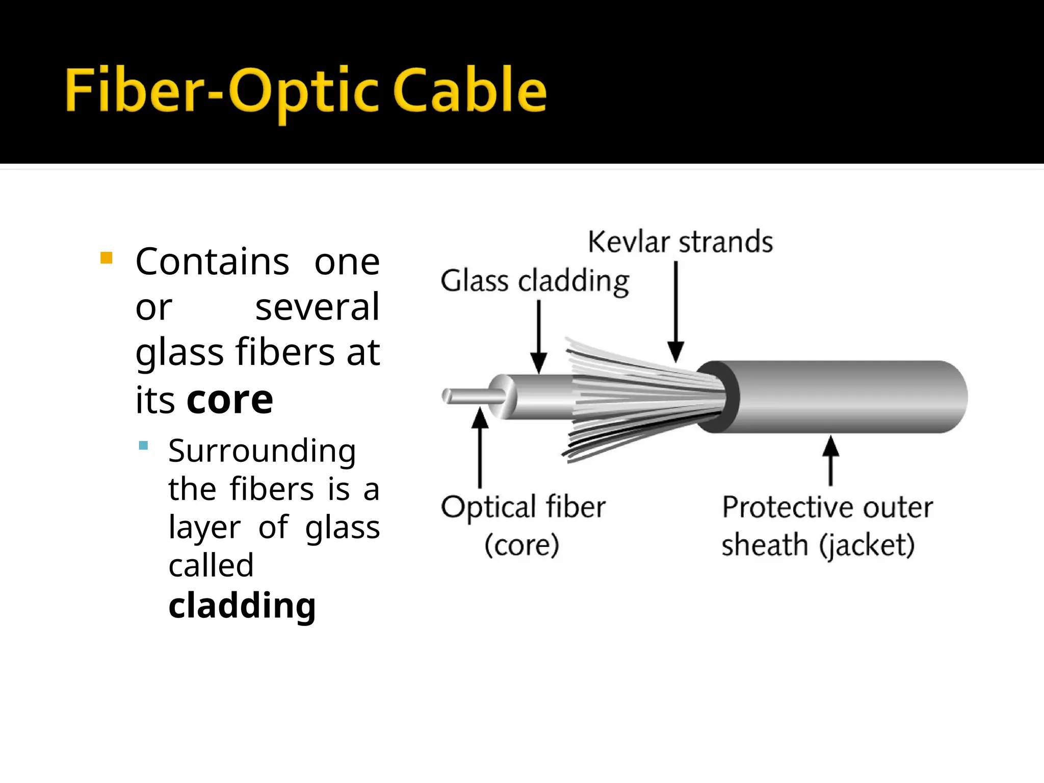
Contains one
orseveral
glass fibers at
its core
Surrounding
the fibers is a
layer of glass
called
cladding
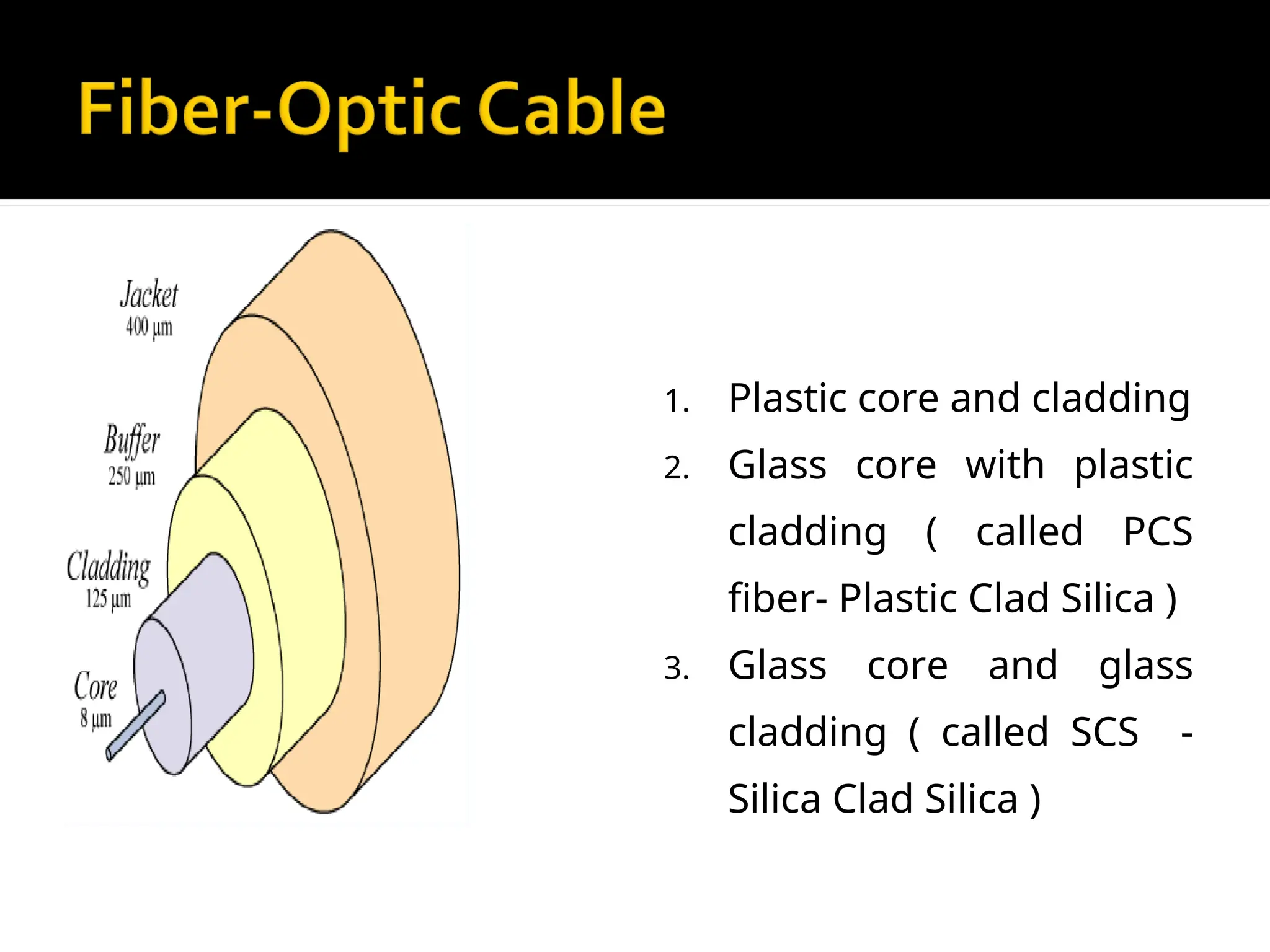
22.
3 TYPES OFOPTICAL FIBERS
1. Plastic core and cladding
2. Glass core with plastic
cladding ( called PCS
fiber- Plastic Clad Silica )
3. Glass core and glass
cladding ( called SCS -
Silica Clad Silica )
23.
Photons (light“particles”)
light represented by tiny bundles of
energy (or quanta), following straight
line paths along the rays.
24.
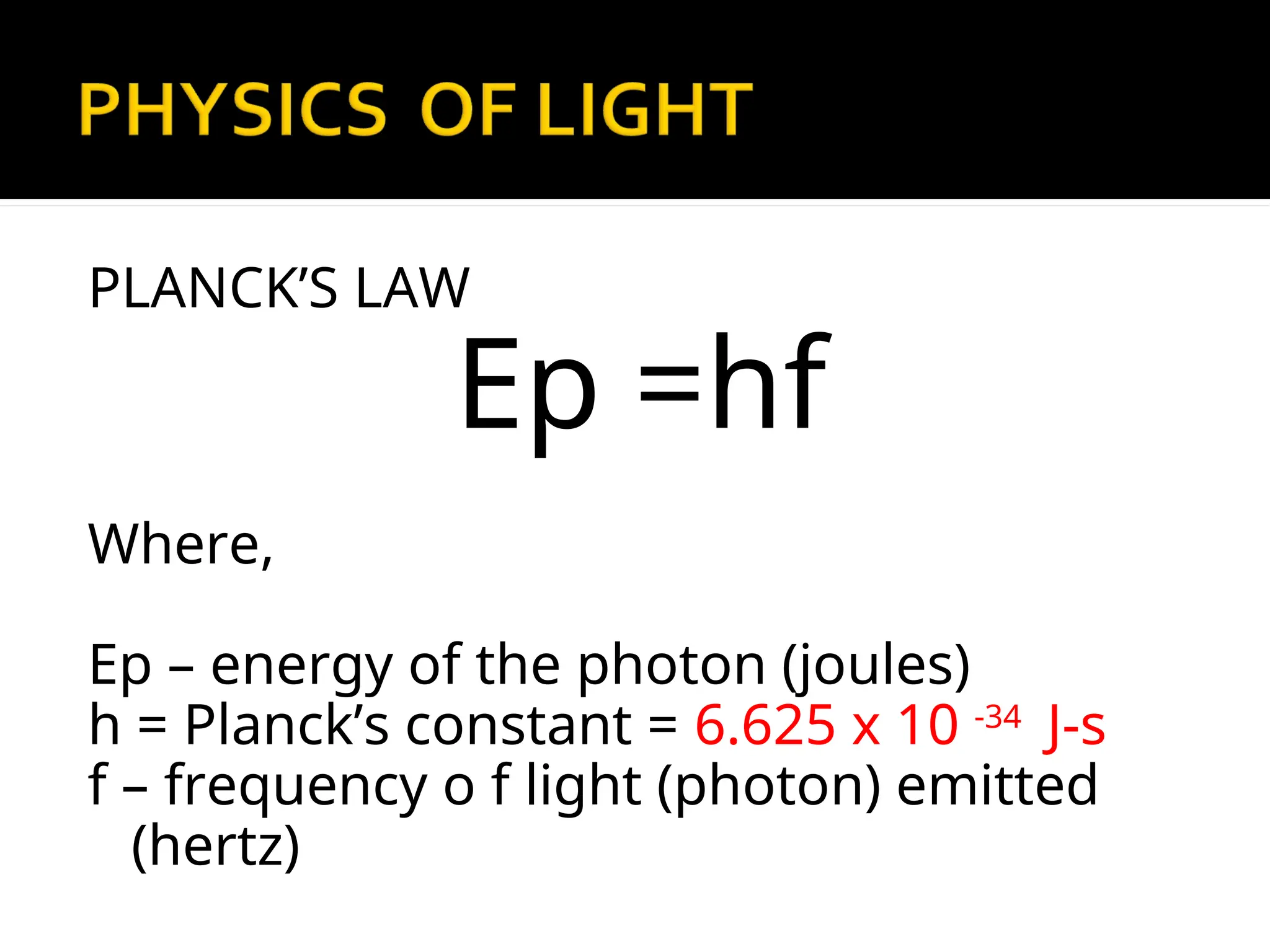
PLANCK’S LAW
Ep =hf
Where,
Ep– energy of the photon (joules)
h = Planck’s constant = 6.625 x 10 -34
J-s
f – frequency o f light (photon) emitted
(hertz)
28.
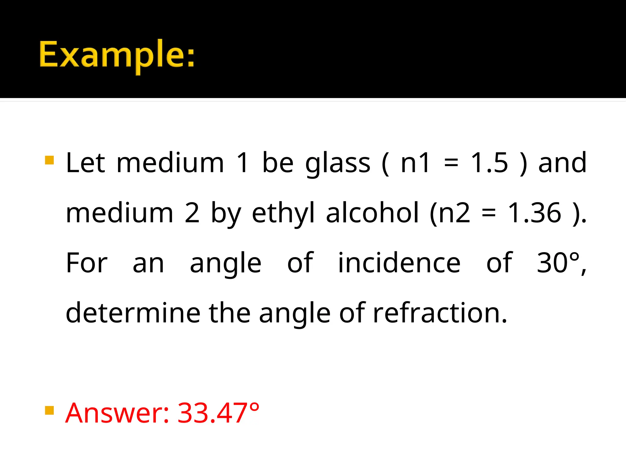
Let medium1 be glass ( n1 = 1.5 ) and
medium 2 by ethyl alcohol (n2 = 1.36 ).
For an angle of incidence of 30°,
determine the angle of refraction.
Answer: 33.47°
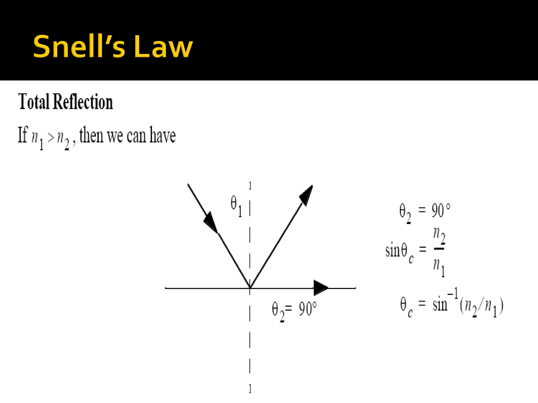
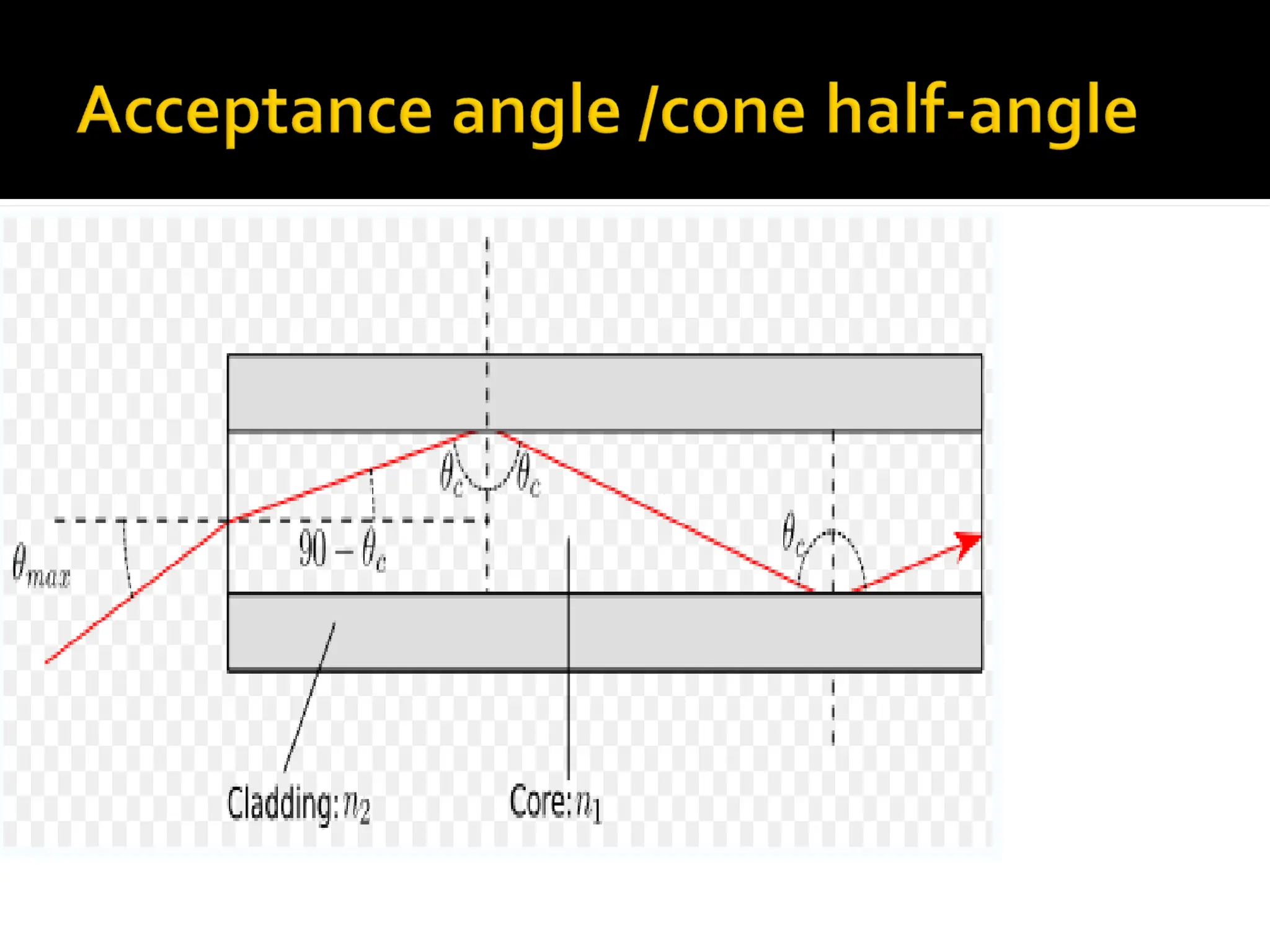
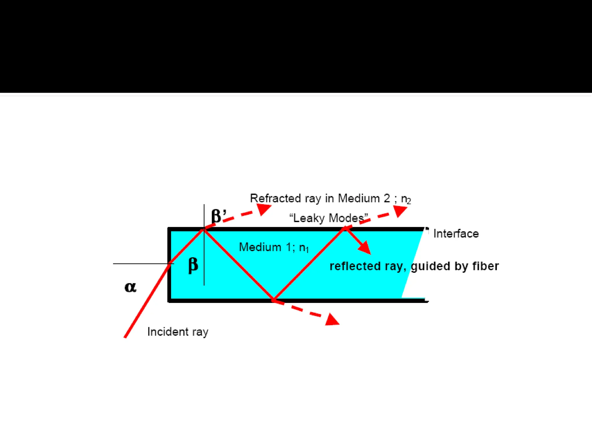
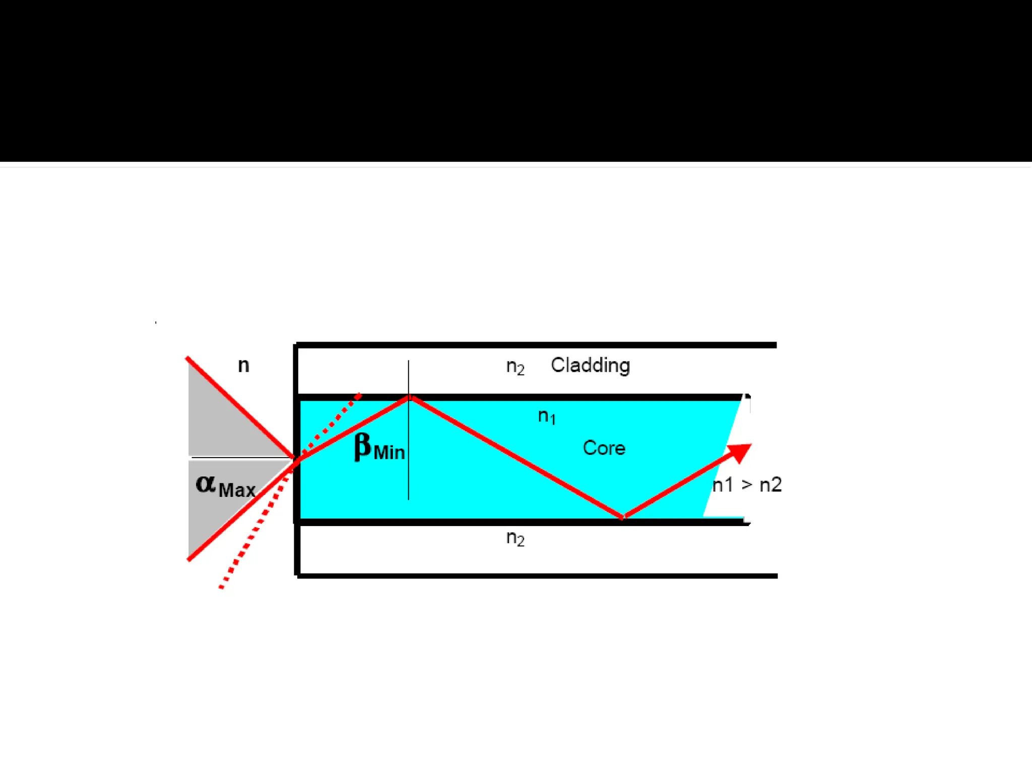
31.
The minimumangle of incidence at
which a light ray ay strike the interface
of two media and result in an angle of
refraction of 90° or greater.
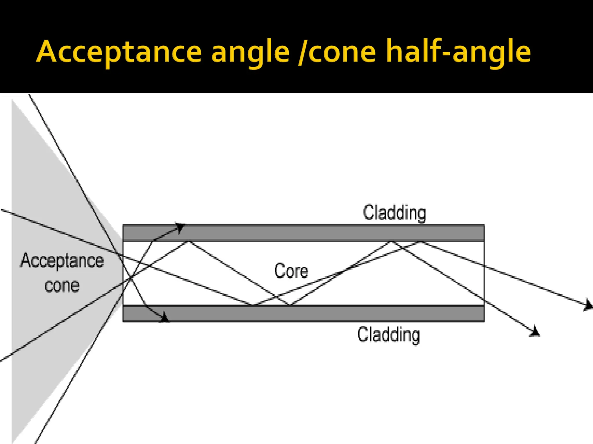
32.
The maximumangle in which external
light rays may strike the air/glass
interface and still propagate down the
fiber.
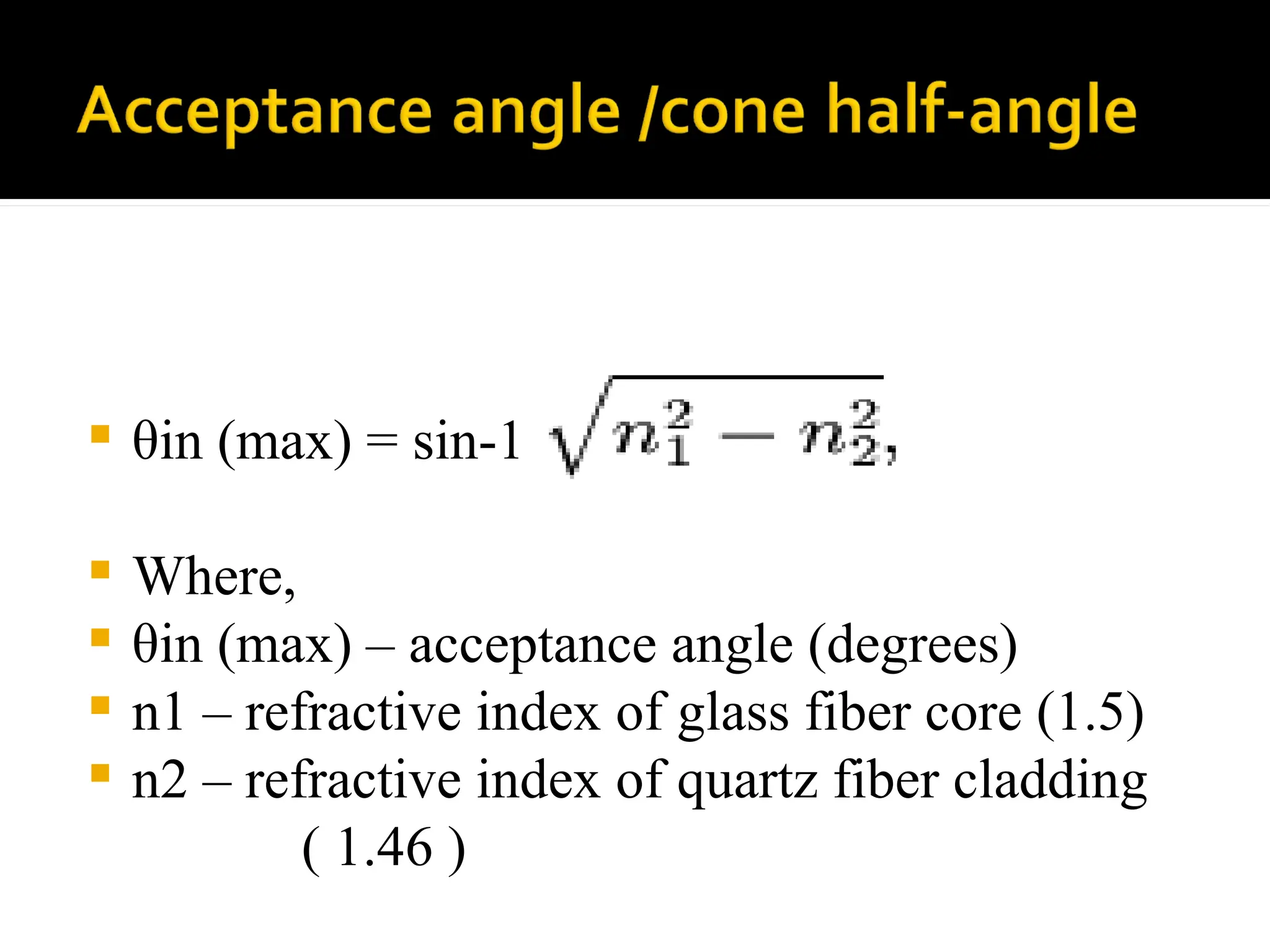
34.
θin (max)= sin-1
Where,
θin (max) – acceptance angle (degrees)
n1 – refractive index of glass fiber core (1.5)
n2 – refractive index of quartz fiber cladding
( 1.46 )
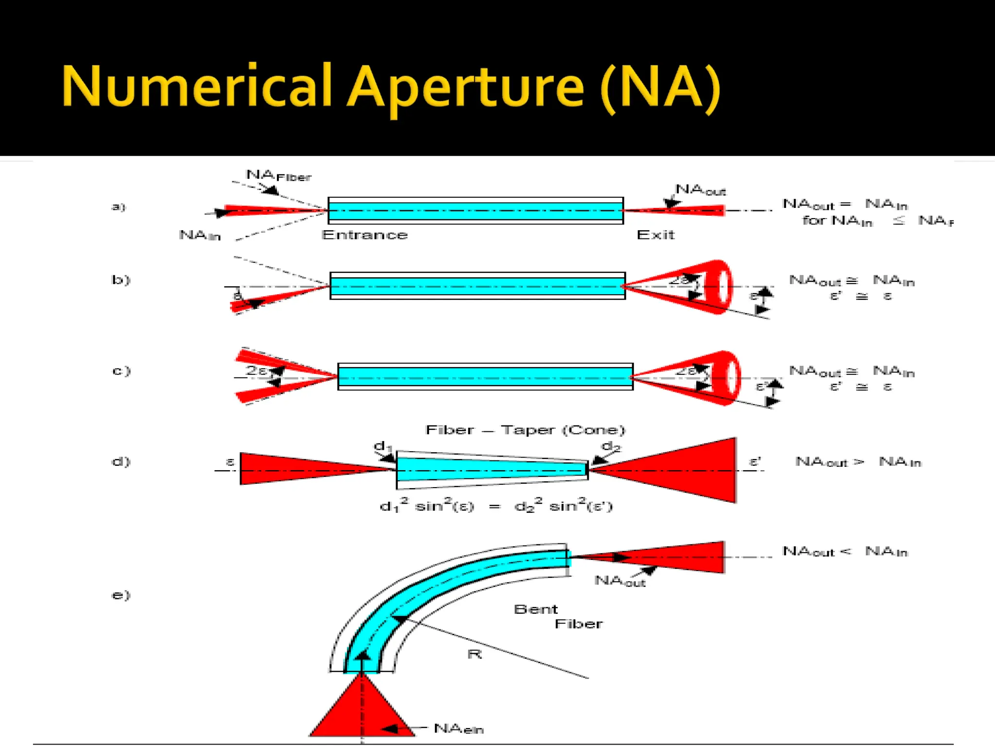
Used todescribe the light-gathering or light-
collecting ability of an optical fiber.
In optics, the numerical aperture (NA) of an
optical system is a dimensionless number
that characterizes the range of angles over
which the system can accept or emit light
40.
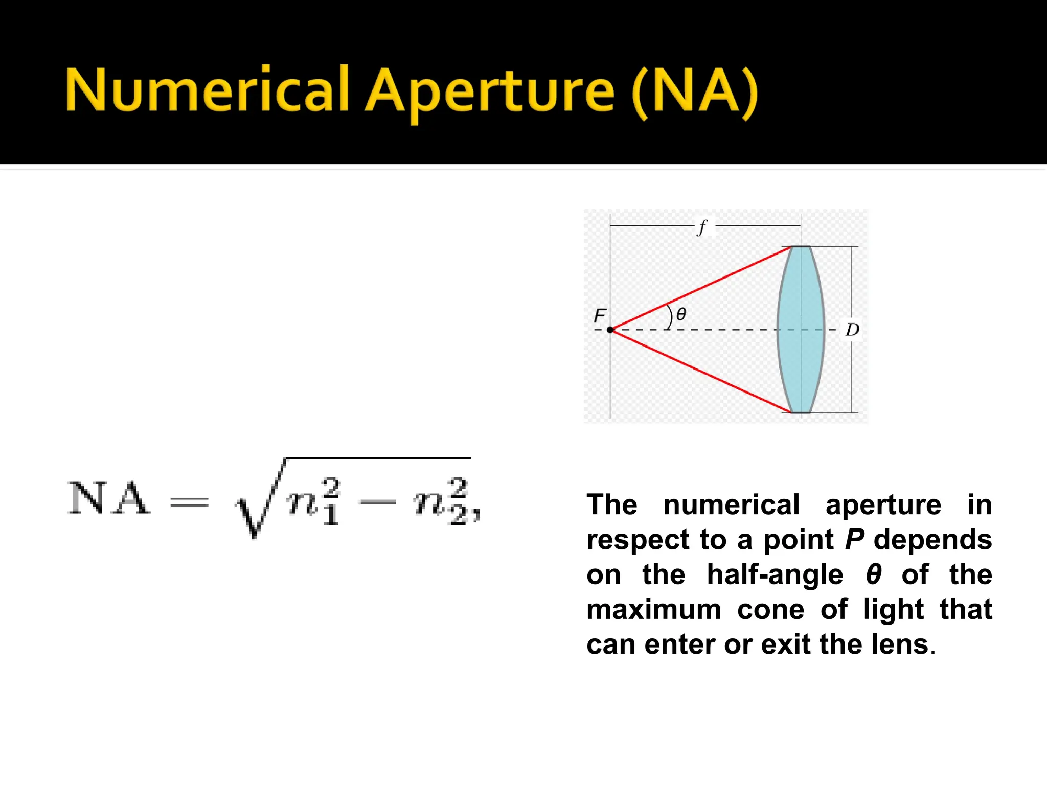
The numerical aperturein
respect to a point P depends
on the half-angle θ of the
maximum cone of light that
can enter or exit the lens.
42.
Two maincategories of
optical fiber used in
fiber optic
communications are
multi-mode optical fiber
and
single-mode optical fibe
r
.
43.
Single-mode fibers– used to transmit
one signal per fiber (used in telephone
and cable TV). They have small cores(9
microns in diameter) and transmit infra-
red light from laser.
44.
Single-mode fiber’ssmaller core (<10
micrometres) necessitates more
expensive components and
interconnection methods, but allows
much longer, higher-performance links.
45.
Multi-mode fibers– used to transmit
many signals per fiber (used in
computer networks). They have larger
cores(62.5 microns in diameter) and
transmit infra-red light from LED.
46.
Multimode fiberhas a
larger core ( 50
≥
micrometres),
allowing less precise,
cheaper transmitters
and receivers to
connect to it as well as
cheaper connectors.
47.
However, multi-modefiber introduces
multimode distortion which often limits
the bandwidth and length of the link.
Furthermore, because of its higher dopant
content, multimode fiber is usually more
expensive and exhibits higher attenuation.
48.
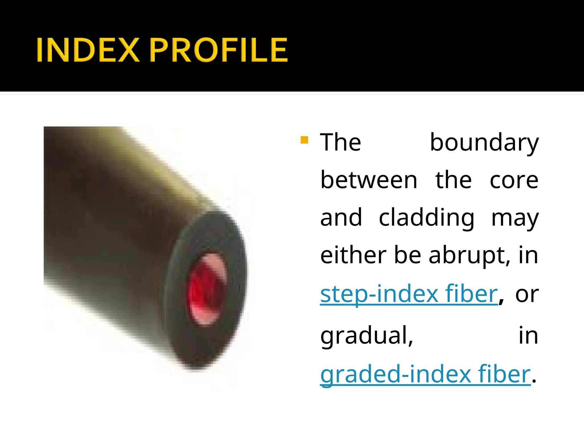
The indexprofile of an optical fiber is a
graphical representation of the magnitude
of the refractive index across the fiber.
The refractive index is plotted on the
horizontal axis, and the radial distance from
the core axis is plotted on the vertical axis.
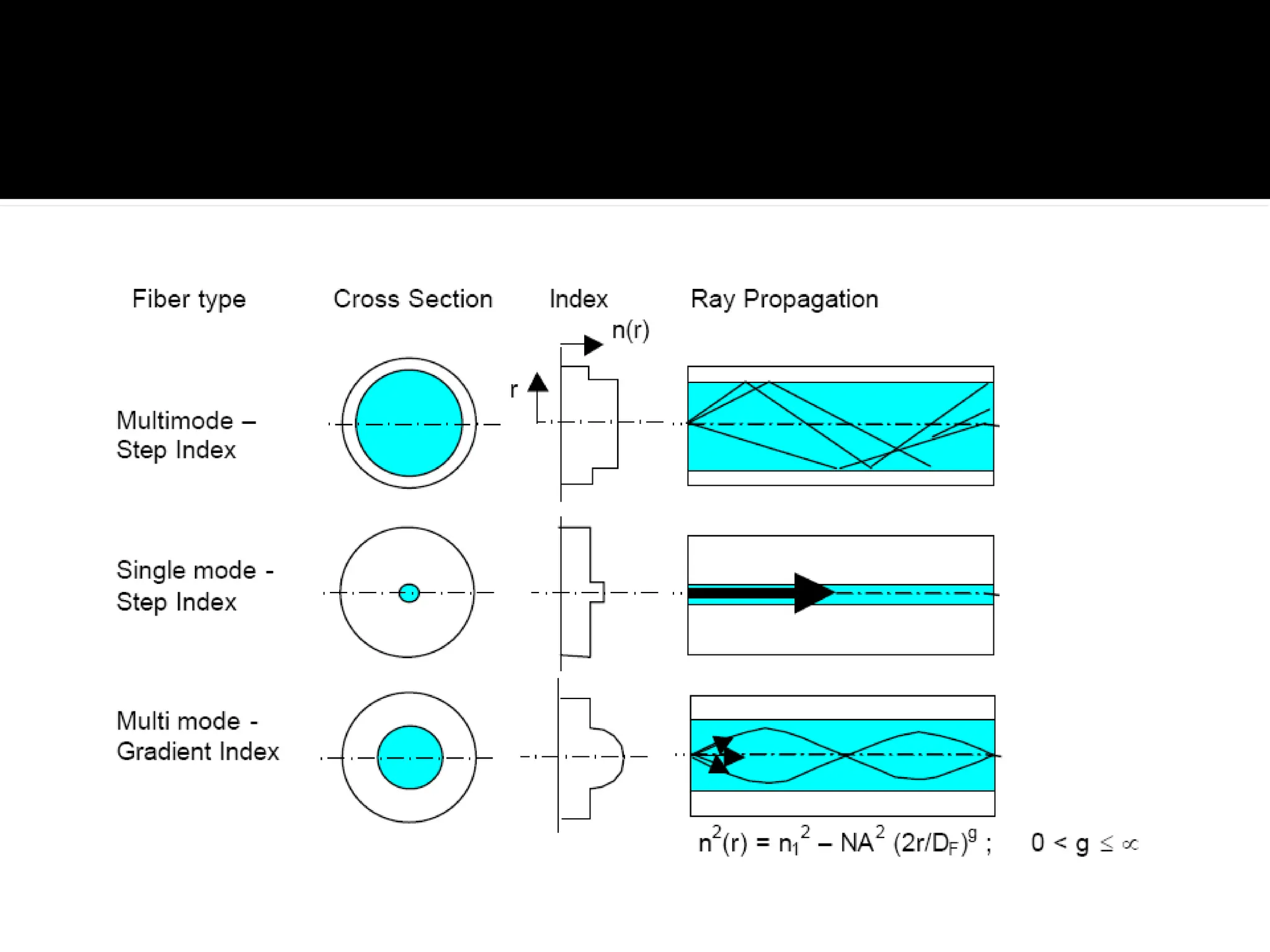
49.
The boundary
betweenthe core
and cladding may
either be abrupt, in
step-index fiber, or
gradual, in
graded-index fiber.
50.
A step-indexfiber has a central core with a
uniform refractive index. An outside
cladding that also has a uniform refractive
index surrounds the core;
however, the refractive index of the
cladding is less than that of the central core.
51.
In graded-indexfiber, the index of refraction
in the core decreases continuously between
the axis and the cladding. This causes light
rays to bend smoothly as they approach the
cladding, rather than reflecting abruptly
from the core-cladding boundary.
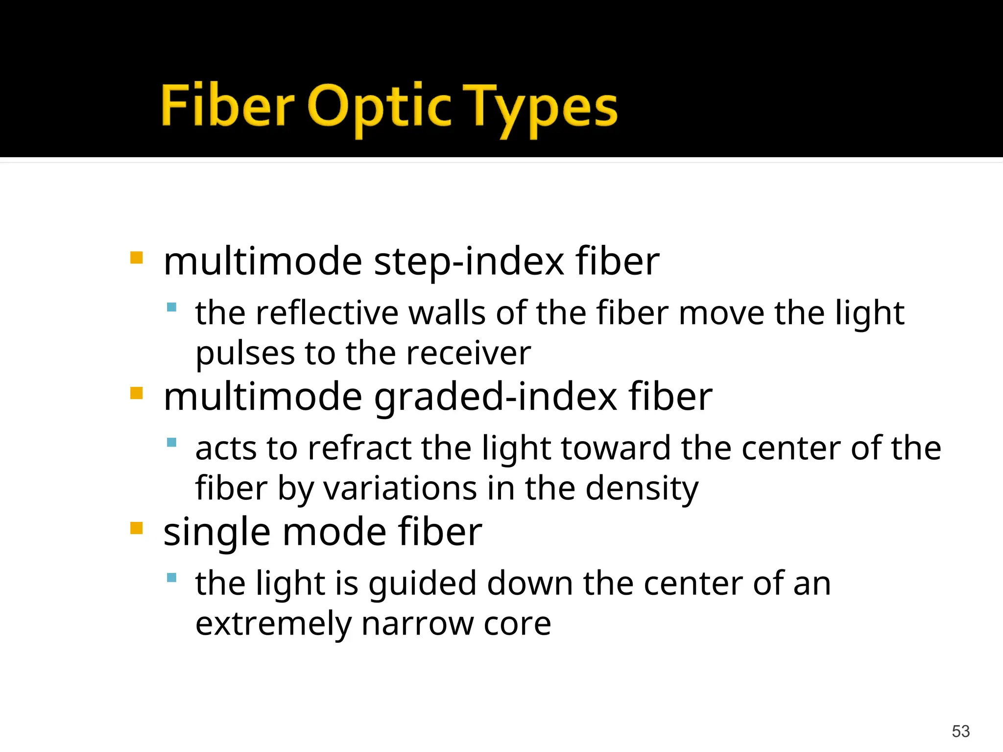
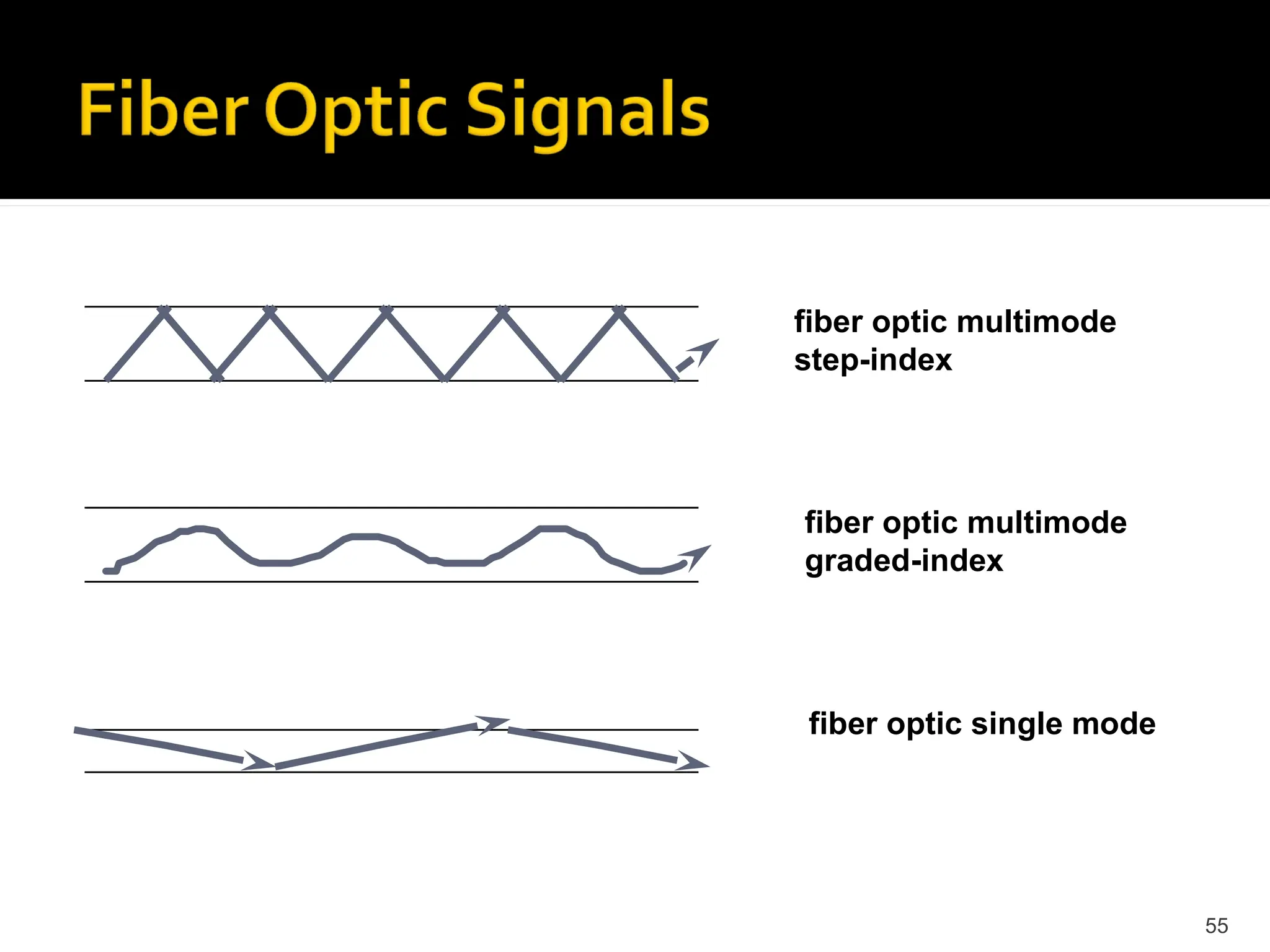
53.
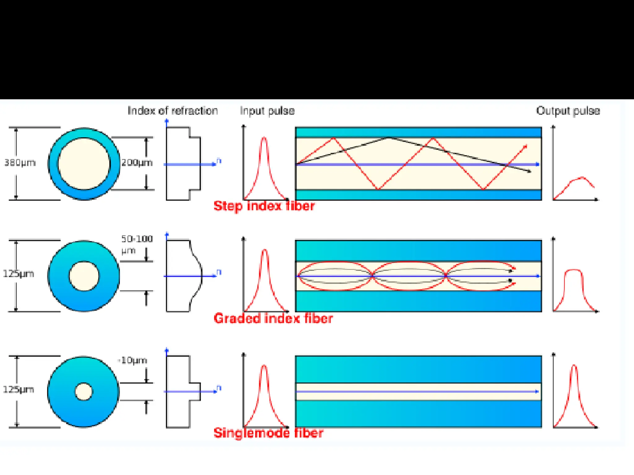
multimode step-indexfiber
the reflective walls of the fiber move the light
pulses to the receiver
multimode graded-index fiber
acts to refract the light toward the center of the
fiber by variations in the density
single mode fiber
the light is guided down the center of an
extremely narrow core
53
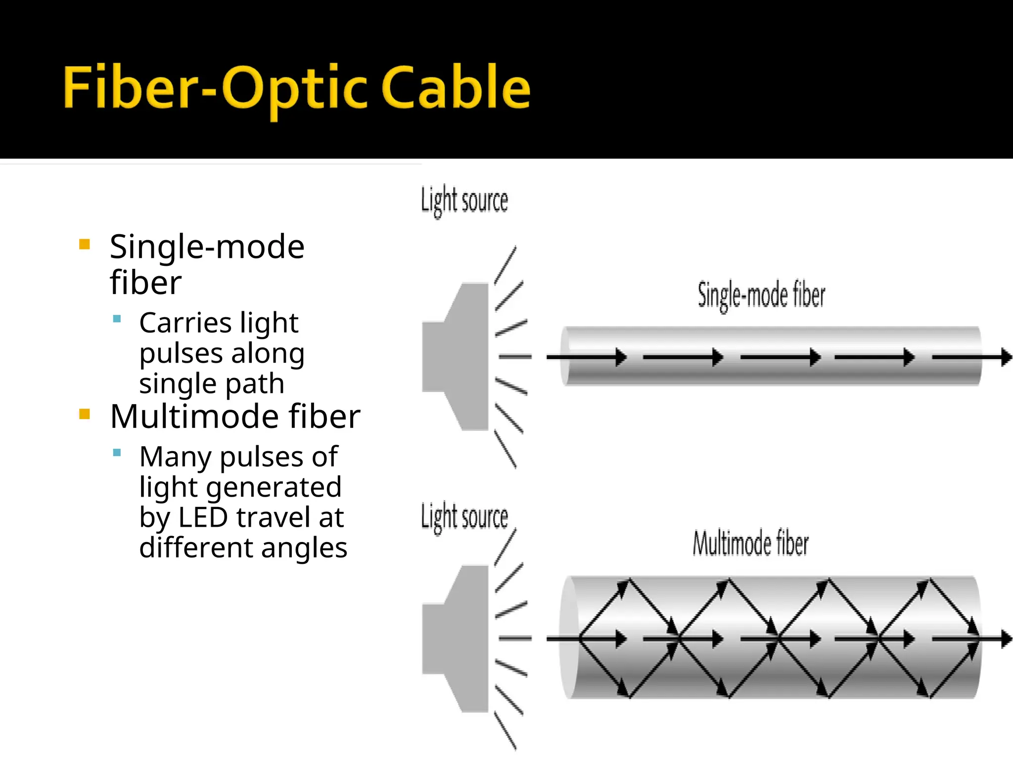
54.
Single-mode
fiber
Carrieslight
pulses along
single path
Multimode fiber
Many pulses of
light generated
by LED travel at
different angles
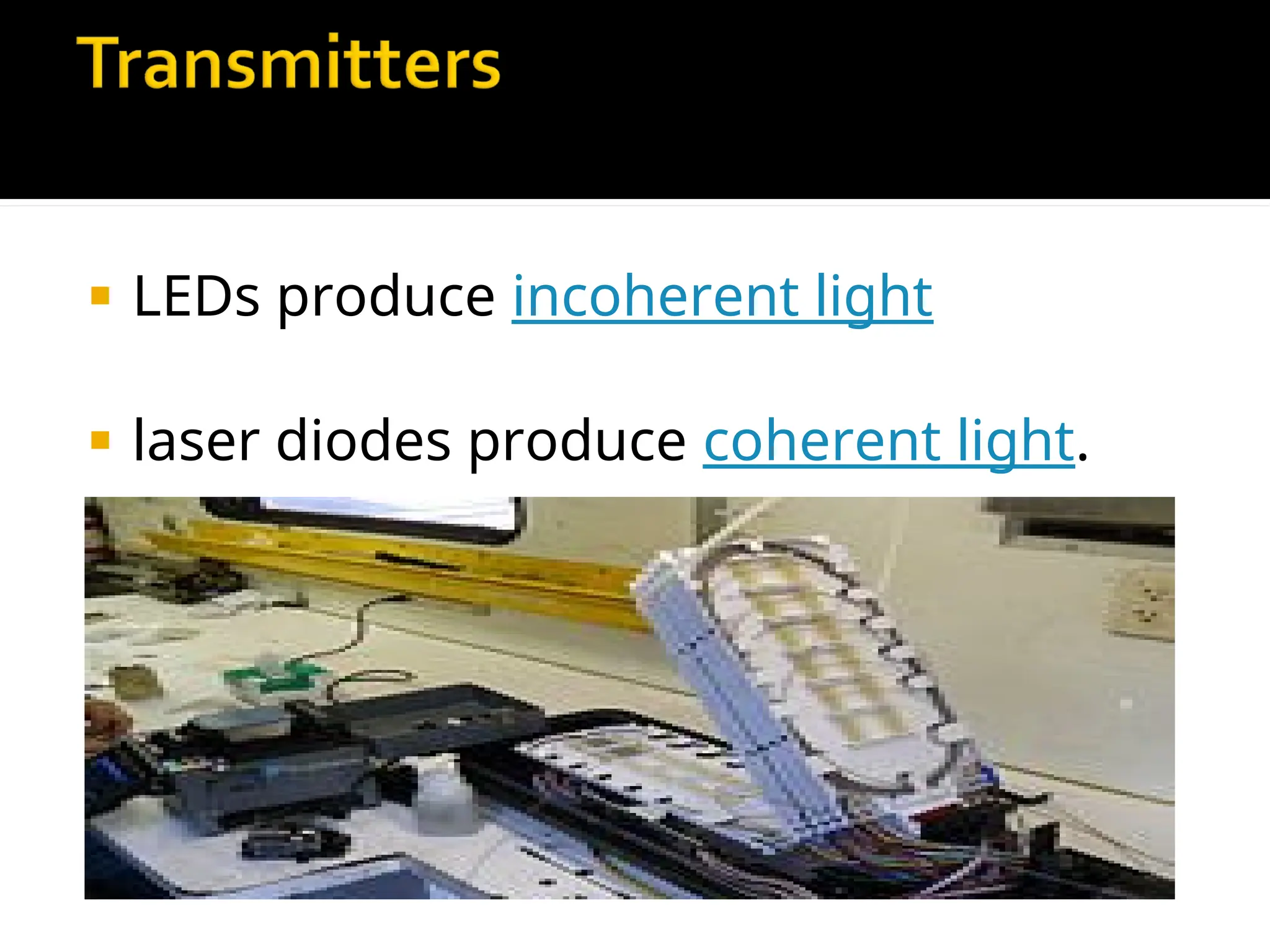
LEDs produceincoherent light
laser diodes produce coherent light.
59.
LED isa forward-biased p-n junction,
emitting light through
spontaneous emission, a phenomenon
referred to as electroluminescence.
The emitted light is incoherent with a
relatively wide spectral width of 30-60 nm.
60.
LED lighttransmission is also inefficient, with
only about 1 % of input power, or about 100
microwatts, eventually converted into
«launched power» which has been coupled
into the optical fiber.
However, due to their relatively simple design,
LEDs are very useful for low-cost applications.
61.
Communications LEDsare most commonly
made from gallium arsenide phosphide
(GaAsP) or gallium arsenide (GaAs)
Because GaAsP LEDs operate at a longer
wavelength than GaAs LEDs (1.3 micrometers
vs. 0.81-0.87 micrometers), their output
spectrum is wider by a factor of about 1.7.
62.
LEDs aresuitable primarily for local-area-network
applications with bit rates of 10-100 Mbit/s and
transmission distances of a few kilometers.
LEDs have also been developed that use several
quantum wells to emit light at different
wavelengths over a broad spectrum, and are
currently in use for local-area WDM networks.
63.
A semiconductorlaser emits light
through stimulated emission rather
than spontaneous emission, which
results in high output power (~100 mW)
as well as other benefits related to the
nature of coherent light.
64.
The outputof a laser is relatively directional,
allowing high coupling efficiency (~50 %) into single-
mode fiber. The narrow spectral width also allows
for high bit rates since it reduces the effect of
chromatic dispersion. Furthermore, semiconductor
lasers can be modulated directly at high frequencies
because of short recombination time.
65.
Laser diodesare often directly
modulated, that is the light output is
controlled by a current applied directly
to the device.
66.
The maincomponent of an optical
receiver is a photodetector that
converts light into electricity through
the photoelectric effect.
67.
The photodetectoris typically a
semiconductor-based photodiode, such
as a p-n photodiode, a p-i-n
photodiode, or an avalanche
photodiode.
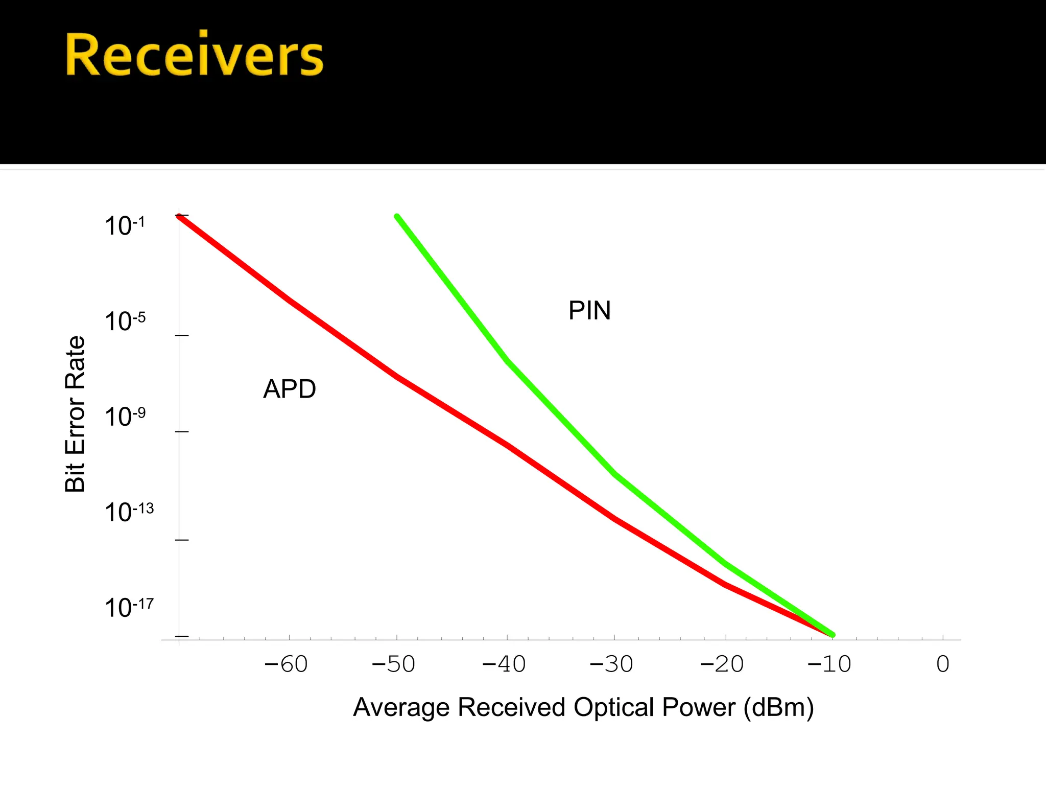
-60 -50 -40-30 -20 -10 0
10-1
10-5
10-9
10-13
10-17
Average Received Optical Power (dBm)
Bit
Error
Rate
APD
PIN
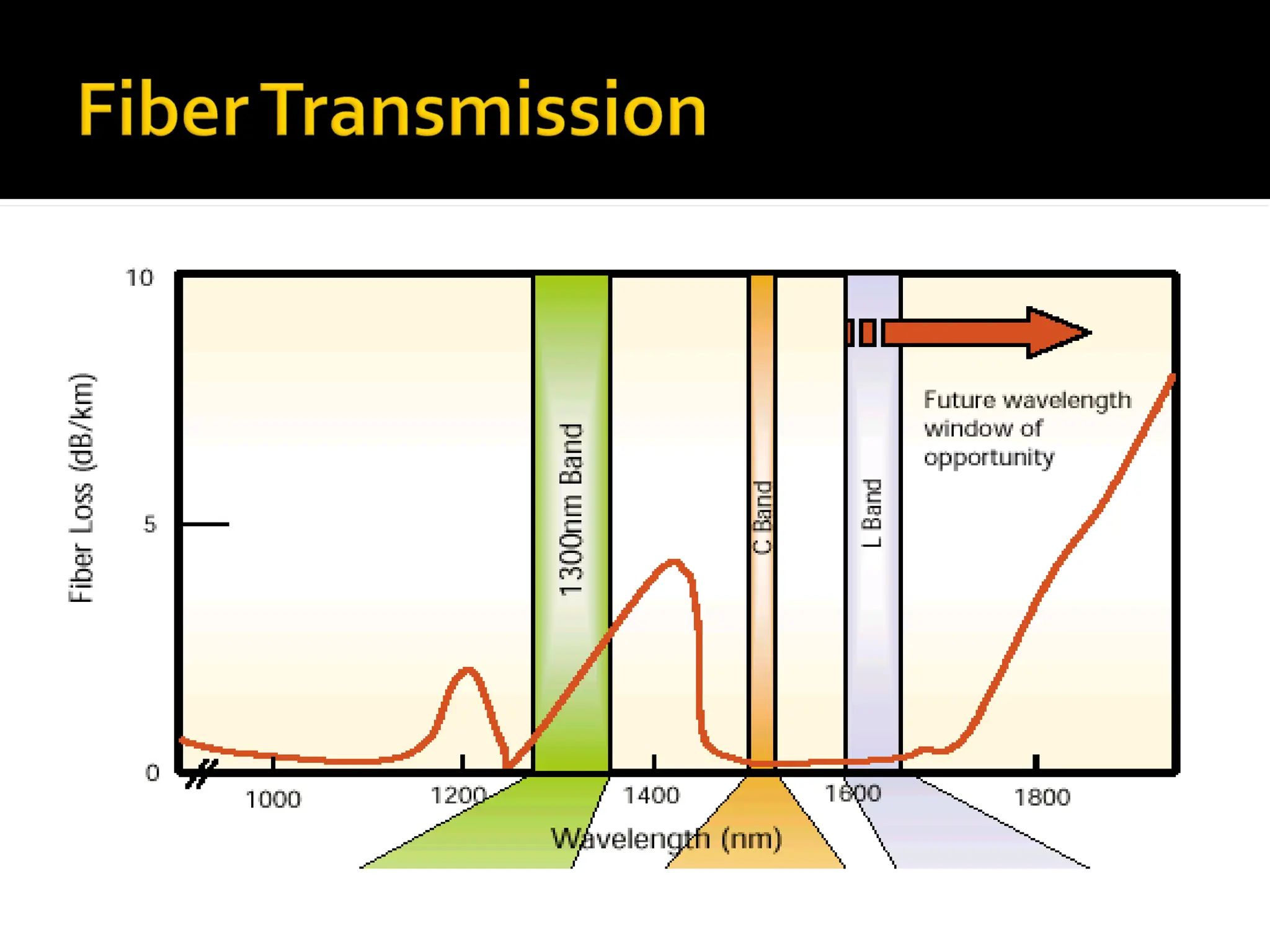
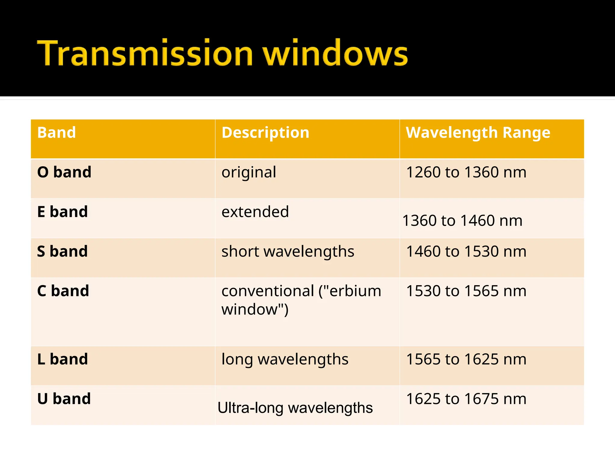
71.
Band Description WavelengthRange
O band original 1260 to 1360 nm
E band extended
1360 to 1460 nm
S band short wavelengths 1460 to 1530 nm
C band conventional ("erbium
window")
1530 to 1565 nm
L band long wavelengths 1565 to 1625 nm
U band
Ultra-long wavelengths
1625 to 1675 nm
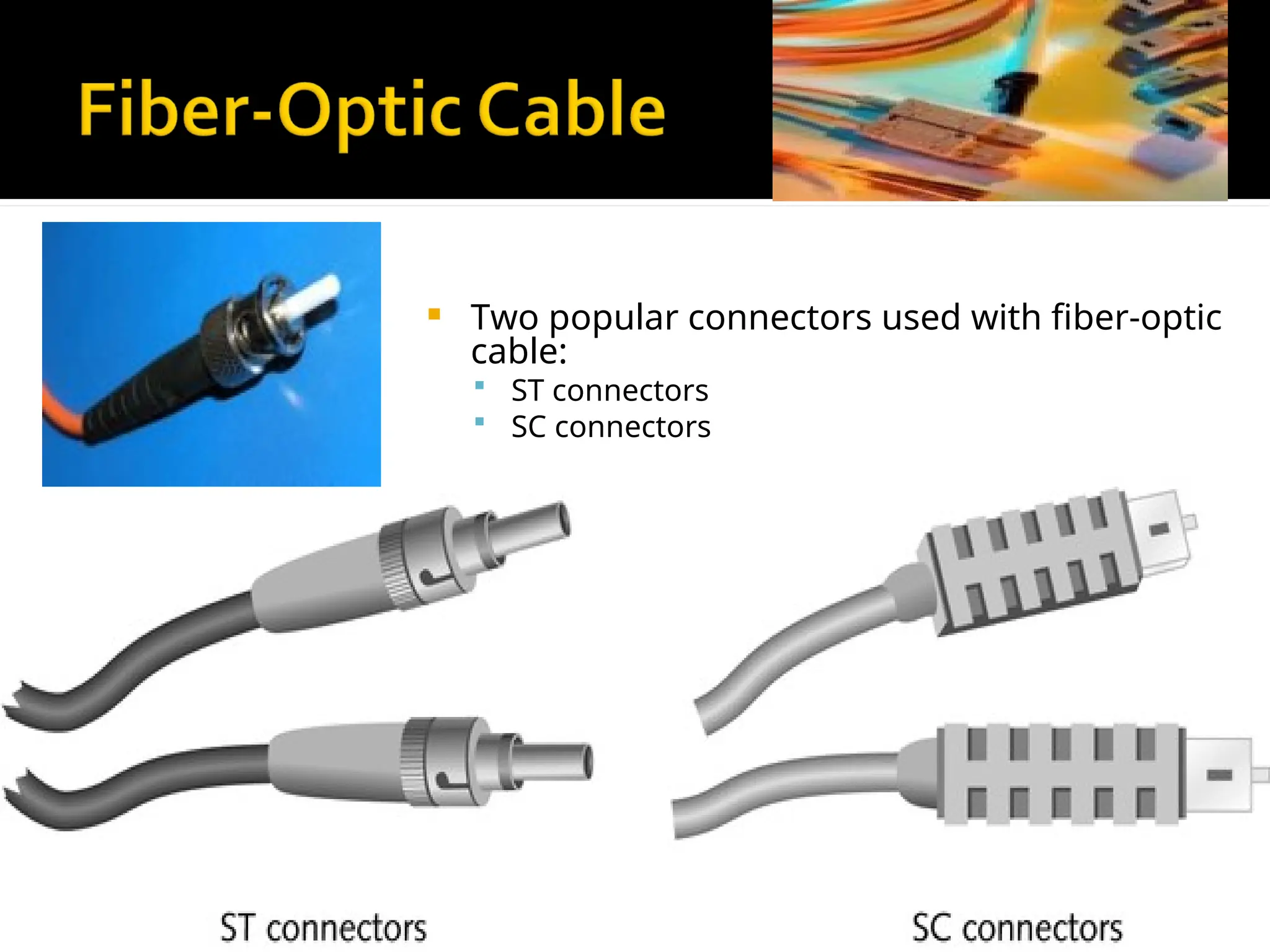
72.
Two popularconnectors used with fiber-optic
cable:
ST connectors
SC connectors