A Single-stage PhotoVoltaic Grid-Connected Inverter using SPWM. It was simulated and modeled with MATLAB/SIMULINK. It was simulated with constant and variable irradiation profiles. I got the results with variations in PV characteristics with different irradiation with SPWM technique.
PV Hybrid System with DSTATCOM for Residential ApplicationsIDES Editor
Now a days PV based energy systems are playing a
vital role among all the renewable energy sourcesin our day
to day life.Proper control should be required to meet the exact
load conditions such that it should satisfy the non-linear
nature of both the solar irradiance and load. In this paper, a
battery is also incorporated along with the PV system to meet
the necessary drop due to change in weather conditions. Here,
a proper control is achieved by using DSTATCOM to
compensate the reactive power. This paper proposes an
advanced technique of PWM to generate the gating pulses
and applied to a Cascaded H-Bridge multilevel inverter to
improve the voltage quality. Here, the entire system is designed
to meet the load of Mogulthur (W.G.Dt. Andhra Pradesh).
Simulation results are presented through Matlab/Simulink
by taking different cases into consideration.
This paper investigates the performances of different photovoltaic (PV) array under several shading condition. Four types of photovoltaic array configuration scheme which are ‘Series’ (S), Series-Parallel’ (SP), Total-Cross-Tied’ (TCT), and ‘Bridge-Link’ (BL) array topologies were tested by applying a 6x6 PV array under 6 different shading scenarios. The modeling is developed using Matlab/Simulink. The performances and output characteristics of photovoltaic array are compared and analyzed. System engineer can use the detailed characteristics of different array configuration to approximate the outcome power and pick the best configuration of the system by concerning the current natural condition to enhance the overall efficiency.
Modeling and Simulation of Solar Photovoltaic module using Matlab/SimulinkIOSR Journals
Abstract: This paper presents the circuit model of photovoltaic (PV) module. Simulation and modeling is done
using MATLAB/ Simulink software package. The proposed model is user friendly and can be used as a common
platform for both applied physics scientist and power electronics engineers. A detailed modeling procedure is
presented. The designed model is verified by using STP255-20/Wd PV module. The IV and PV characteristics
are simulated at different temperature and irradiance conditions and the results are verified. The proposed
model is very simple fast and accurate. The designed model can be used for analysis of PV characteristics and
for simulation of maximum power point tracking algorithms
International Journal of Engineering Research and DevelopmentIJERD Editor
Electrical, Electronics and Computer Engineering,
Information Engineering and Technology,
Mechanical, Industrial and Manufacturing Engineering,
Automation and Mechatronics Engineering,
Material and Chemical Engineering,
Civil and Architecture Engineering,
Biotechnology and Bio Engineering,
Environmental Engineering,
Petroleum and Mining Engineering,
Marine and Agriculture engineering,
Aerospace Engineering.
Simulation Model for PV Array & Its CharacteristicsIJEEE
This paper presents the implementation of a photovoltaic model using Matlab software, which can be representative of PV cell module, and array for easy use on simulation. The proposed model is designed with a user-friendly icon and a dialog box like Simulink block libraries. This makes the PV model easily simulated and analyzed in conjunction with power electronics for a maximum power point tracker.
Drive Applications of Fuzzy Logic Controlled Interleaved Boost Converter for ...EECJOURNAL
The improvement in the efficiency, a reduced ripple and reduction in the passive elements is proposed in this project through the interleaved boost converter. The interleaved boost converter operates multiple phase approach, is used for the power factor control applications. The proposed converter is used to extract the power output from the solar panel with reduced ripple losses and greater efficiency thereby obtaining the maximum power from the solar panel. The control of the current with energy saving method is obtained with the efficiency of 95%. The converter operation is controlled by the fuzzy logic controller to operate the switches with the finest and reduced power loss constrains. The proposed method is mathematically modeled and the results are analysed. A similar prototype model is designed and the results are compared with the theoretical values.
Design and validation of piezoelectric energy harvesting systemsIlyas Caluwé
The aim of this study is to examine how small amounts of ambient energy, such as in vibrations or wind flow, can be converted to electrical energy and to build a working design.
The different energy harvesting principles found in literature are studied first. Piezoelectric energy harvesting was found suitable for both energy harvesting out of ambient vibrations and wind flow. A cantilevered beam setup with a piezopatch (MFC patch) is chosen because it has good power conversion characteristics, it is robust and versatile. Both vibration and wind flow harvesting devices can be constructed with this setup.
Vibration harvesting setups were constructed with both a commercially available bimorph piezoceramic harvester and with an unimorph harvester consisting of a stainless steel plate and a composite-reinforced piezoceramic patch attached to it. The power output is reported. The parameters that are of importance to optimize the setup are discussed.
The possibilities to use the beam for wind flow harvesting were explored. Different aeroelastic phenomena were studied to give insight into possible working principles. A number of designs are proposed and some are tested using the stainless steel plate with the MFC patch. The possibility of using aeroelastic stability to harvest energy is shown, and suggestions for further improvements are given.
Nowadays tremendous increase in renewable energy technologies available in abounding nature energy extracted from sun, wind etc. This Proposed topology gathered maximum power using multi input ky boost converters for hybrid energy. This hybrid topology operates mainly delivered the power from renewable energy sources solar/wind to dc bus. In the absence of any one source, wind or solar supplies power to the dc bus. Without any renewable energy sources battery deliver the power to dc bus.An inverter type module convert the power from dc bus to ac grid. In this paper effectiveness of hybrid renewable energy is simulated through MATLAB/SIMULINK.
A Novel Approach on Photovoltaic Technologies for Power Injection in Grid Usi...IJERA Editor
The paper presents the simulation of the Solar Photovoltaic module using Matlab Simulink. This model is based on mathematical equations and is described through an equivalent circuit including a photocurrent source, a diode, a series resistor and a shunt resistor. This paper presents integration of the grid distribution network in Indian scenario with solar power technology to meet the additional electrical energy demand of urban as well as rural sectors which are both rapidly expanding. First of all the data of a real life power plant having 24V, 230W Power PV module has been compared and analyzed with that of matlab program output for identical module and it has been find out that a variation in temperature affects the parameters values as well as the performance of the solar module. After the above analysis the design and Simulink implementation for single phase power grid connected PV system has been done. The system includes the PV array model, the integration of the MPPT with boost dc converter , dc to ac inverter, single phase series load connected to ac grid. It is demonstrated that the model works well at different temperature conditions and predicting the General behavior of single-phase grid- connected PV systems .
Modeling of solar array and analyze the current transientEditor Jacotech
Spacecraft bus voltage is regulated by power
conditioning unit using switching shunt voltage regulator having
solar array cells as the primary source of power. This source
switches between the bus loads and the shunt switch for fine
control of spacecraft bus voltage. The effect of solar array cell
capacitance [5][6] along with inductance and resistance of the
interface wires between solar cells and power conditioning
unit[1], generates damped sinusoidal currents superimposed on
the short circuit current of solar cell when shunted through
switch. The peak current stress on the shunt switch is to be
considered in the selection of shunt switch in power conditioning
unit. The analysis of current transients of shunt switch in PCU
considering actual spacecraft interface wire length by
illumination of solar panel (combination of series and parallel
solar cells) is difficult with hardware simulation. Software
simulation by modeling solar cell is carried out for a single string
(one parallel) in Pspice [6]. Since in spacecrafts number of
parallels and interface cable length are variable parameters the
analysis of current transients of shunt switch is carried out by
modeling solar array with the help of solar cell model[6] for the
actual spacecraft condition.
The main factors affecting on value of maximum power point photovoltaic model...Ali Mahmood
A Matlab-Simulink based simulation study of photovoltaic (PV) cells
is carried out and presented in this paper. The study is helpful in results showed that
Maximum Power Point (MPP) strongly depends on sun irradiance, shunt resistance,
series resistance, temperature and ideal factor. These results might be used as a
guide for PV system users.
New Structure for Photovoltaic SystemApplications with Maximum Power Point Tr...IAES-IJPEDS
This paper recommendes a new structure for photovoltaicsystems with a new inverter topology. A quasi-Z-source DC-DC converter with capability of dividing its output voltage to the same voltages and tracking maximum power point is proposed. The proportional-integral incremental conductance method is used for maximum power point tracking. The new recommended inverter topology is linked to quasi-Z-source converter for transferring power. For triggering inverter switches, alternate phase opposition disposition switching technique is utilized. A comparison is drawn between suggested multilevel inverter topology and other conventional multilevel inverter topologies. Description of proposed structure along with detailed simulation results that verify its feasibility are given to demonstrate the availability of the proposed system by MATLAB/Simulink software.
The main objective of this research work is to develop KY conveter topology for renewable energy sources.Solar energy is the readily available and is the cheapest form of energy. It is non-polluting and environment friendly. The development of high static gain DC-DC converters is an important research area due to the crescent demand of this technology for several applications supplied by low DC output voltage power sources. It is used to provide the uninterruptable power supply and battery powered to the system. So here, step-up DC-DC converters based on the KY converter are proposed for LED lighting systems. The proposed topologies present high voltages and high efficiency for low input voltage and high output voltage applications. The simulation results of the proposed topology have been presented using MATLAB/SIMULINK software.
This paper describes the Grid connected solar photovoltaique system using DC-DC boost converter and the DC/AC inverter (VSC) to supplies electric power to the utility grid. The model contains a representation of the main components of the system that are two solar arrays of 100 kW, boost converter and the grid side inverter. The paper starts with a system description, in this part we have given a definition and a short overview of every component used in this system and they are taken separately. The PV cell model is easy, accurate, and takes external temperature and solar radiation into consideration. It also proposes a maximum power point tracking (MPPT) algorithm. The algorithm incorporated in a DC/DC converter is used to track the maximum power of PV cell. Finally, the DC/AC inverter (VSC) of three- level is used to regulate the ouput voltage of DC/DC converter and connects the PV cell to the grid. Simulation results show how a solar radiation’s change can affect the power output of any PV system, also they show the control performance and dynamic behavior of the grid connected photovoltaic system.
Solar Photo Voltaic Water Pumping: Harnessing Maximum PowerIDES Editor
Among alternate sources of electricity, Solar Photo
Voltaic (PV) energy is gaining prominence due to its plentiful
availability. Water pumping is an important application of
solar PV power. However people are not opting for it in large
numbers as the ‘cost per watt’ for solar pumping systems is
high. The cost can be reduced by harnessing more power per
unit installed capacity of the solar panel. One method of
realising this is by Maximum Power Point Tracking (MPPT)
wherein a power electronic converter is used to match pump
with the PV panel. Widely employed approach for MPPT is to
monitor the PV panel power and keep on adjusting the duty
cycle of converter so that tapped power is always maximum.
Present paper proposes a novel method to realise MPPT for
standalone solar PV water pumping system. It is shown that
the output power becomes the maximum when the motor
voltage becomes the maximum. Conversely, varying the duty
cycle of the converter such that load voltage is always maximum
leads to harnessing maximum power output. This approach
can be referred to as Maximum Load Voltage Point Tracking
(MVPT). We need to monitor only load voltage. It is simpler
than monitoring PV panel power as in that case it’s necessary
to measure both panel voltage and current and then find their
product.
The proposal of MVPT for realizing MPPT is substantiated
by theoretical explanation considering two types of loads: Pure
Resistance and Centrifugal Pump driven by Permanent Magnet
(PM) brushed DC Motor. The Matlab-Simulink based
simulation is also carried out. Simulation results are found
to be in close conformity with the theoretical findings.
Analysis and Modeling of Transformerless Photovoltaic Inverter SystemsIJMER
International Journal of Modern Engineering Research (IJMER) is Peer reviewed, online Journal. It serves as an international archival forum of scholarly research related to engineering and science education.
Z - Source Multi Level Inverter Based PV Generation SystemIJERA Editor
In this paper a novel technique of Z-Source multilevel Inverter based PV Generation system is implemented and simulated using MATLAB-Simulink simulation software. The Photovoltaic cells are healthier option for converting solar energy into electricity. Due to high capital cost and low efficiency PV cells have not yet been a fully smart choice for electricity users. To enhance the performance of the system, Z-Source multi level inverter can be used in place of conventional Voltage Source Inverter (VSI) in Solar Power Generation System. The PV cell model is developed using circuit mathematical equations. The Z-Source multilevel inverter is modeled to realize boosted DC to AC conversion (inversion) with low THD. Outcome shows that the energy conversion efficiency of ZSMLI is a lot improved as compared to conventional voltage Source Inverter (VSI). By doing FFT analysis we can know the total THD.
Maximum Power Point Tracking Method for Single Phase Grid Connected PV System...Ali Mahmood
Ordinary technique fail to ensure successful tracking of the maximum power point under partial shading conditions (PSC). This performs in significant reduction in the power generated as well as the reliability of the photovoltaic energy production system. For the effective utilization of solar panel under partial shading condition (PSC), maximum power point tracking method (MPPT) is required.
Nine Level Inverter with Boost Converter from Renewable Energy SourceIJERA Editor
A new single phase nine level multilevel inverter is proposed. The input to the proposed nine level multilevel inverter is obtained from solar panel . The solar energy obtained from the solar panel is not constant and it varies with times. In order to maintain the constant voltage obtained from the solar panel the boost converter is used to maintain the constant output voltage using MPPT ( Perturb and observe algorithm) algorithm. Then the buck boost converter output voltage is stored in the battery bank. Finally the battery energy is connected to the 9 level inverter circuits. The harmonics in the inverter is eliminated by using the fuzzy logic controller. The gate pulse for the multilevel inverter is given by the fuzzy logic controller which in turn reduces the harmonics in the inverter. Then the inverter output is connected to the grid are some application.
International Journal of Engineering Research and Applications (IJERA) is an open access online peer reviewed international journal that publishes research and review articles in the fields of Computer Science, Neural Networks, Electrical Engineering, Software Engineering, Information Technology, Mechanical Engineering, Chemical Engineering, Plastic Engineering, Food Technology, Textile Engineering, Nano Technology & science, Power Electronics, Electronics & Communication Engineering, Computational mathematics, Image processing, Civil Engineering, Structural Engineering, Environmental Engineering, VLSI Testing & Low Power VLSI Design etc.
Performance Investigation of Grid Connected Photovoltaic System Modelling Bas...IJECEIAES
Photovoltaic (PV) systems are normally modeled by employing accurate equations dealing with a behavior the PV system. This model has Characteristic of PV array cells, which are influenced by both irradiation and temperature variations. Grid-connected PV system is considered as electricity generated solar cell system which is connected to the grid utilities. This paper characterizes an exhibiting and simulating of PV system that executed with MATLAB /Simulink. The impact of solar irradiances as well as ambient temperature performances of PV models is investigated and noted that a lower temperature provides maximum power higher so that the open circuit voltage is larger. Furthermore, if the temperature is low, then a considerably short circuit current is low too.
In this paper the multicarrier pulse width modulation (MCPWM) with multi value DC voltage source multilevel inverter is presented. These MLI’s are suitable in high voltage & high power application due to their ability to synthesize waveforms with better harmonic spectrum. Seven level inverter is simulated using MATLAB/Simulink. The use of Photovoltaic Cell as a DC source for the multilevel Inverter is proposed here.
Modeling and Simulation of a Photovoltaic Field for 13 KW IJECEIAES
In the future solar energy will be very important source of energy. More than 45% of needed energy in the world will be generated by photovoltaic module. Therefore it is necessary to concentrate our efforts in order to reduce the application costs .This work investigates on the modeling of a Stand Alone Power System focusing on Photovoltaic energy systems. We introduce the models of the system components Therefore a maximum power point tracking (MPPT) technique is needed to track the peak power in order to make full utilization of PV array output power under varying conditions. This paper presents two widely-adopted MPPT algorithms, perturbation & observation (P&O) and incremental conductance (IC).A complete characterization and simulation model was implemented in the MatlabSimulink environment. Design complete system is done to analyze its behavior for a typical year, with the aim to evaluate their energetic effectiveness.
International Journal of Engineering Research and Applications (IJERA) is an open access online peer reviewed international journal that publishes research and review articles in the fields of Computer Science, Neural Networks, Electrical Engineering, Software Engineering, Information Technology, Mechanical Engineering, Chemical Engineering, Plastic Engineering, Food Technology, Textile Engineering, Nano Technology & science, Power Electronics, Electronics & Communication Engineering, Computational mathematics, Image processing, Civil Engineering, Structural Engineering, Environmental Engineering, VLSI Testing & Low Power VLSI Design etc.
Modeling and Simulation of Fuzzy Logic based Maximum Power Point Tracking (MP...IJECEIAES
This paper presents modeling and simulation of maximum power point tracking (MPPT) used in solar PV power systems. The Fuzzy logic algorithm is used to minimize the error between the actual power and the estimated maximum power. The simulation model was developed and tested to investigate the effectiveness of the proposed MPPT controller. MATLAB Simulink was employed for simulation studies. The proposed system was simulated and tested successfully on a photovoltaic solar panel model. The Fuzzy logic algorithm succesfully tracking the MPPs and performs precise control under rapidly changing atmospheric conditions. Simulation results indicate the feasibility and improved functionality of the system.
Modeling Combined Effect of Temperature, Irradiance, Series Resistance (Rs) a...IJLT EMAS
In this project a single solar cell performance is analysis with change in the various electrical and mechanical parameters. The open circuit voltage and short circuit current (I-V) and P-V of solar cell is varies with the influence electrical and mechanical parameters. In this project we analysis the solar cell with the following parameter such as temperature, irradiance and series resistance (R s) and shunt resistor (R sh). The analysis is done separate and combined effect of temperature and irradiance with series and shunt resistor. The single solar cell model is done by MATLAB-Simulink tool and the output under change in various parameters is verified.
Similar to A single stage photo voltaic grid-connected inverter using spwm (20)
The Art of the Pitch: WordPress Relationships and SalesLaura Byrne
Clients don’t know what they don’t know. What web solutions are right for them? How does WordPress come into the picture? How do you make sure you understand scope and timeline? What do you do if sometime changes?
All these questions and more will be explored as we talk about matching clients’ needs with what your agency offers without pulling teeth or pulling your hair out. Practical tips, and strategies for successful relationship building that leads to closing the deal.
Smart TV Buyer Insights Survey 2024 by 91mobiles.pdf91mobiles
91mobiles recently conducted a Smart TV Buyer Insights Survey in which we asked over 3,000 respondents about the TV they own, aspects they look at on a new TV, and their TV buying preferences.
Essentials of Automations: Optimizing FME Workflows with ParametersSafe Software
Are you looking to streamline your workflows and boost your projects’ efficiency? Do you find yourself searching for ways to add flexibility and control over your FME workflows? If so, you’re in the right place.
Join us for an insightful dive into the world of FME parameters, a critical element in optimizing workflow efficiency. This webinar marks the beginning of our three-part “Essentials of Automation” series. This first webinar is designed to equip you with the knowledge and skills to utilize parameters effectively: enhancing the flexibility, maintainability, and user control of your FME projects.
Here’s what you’ll gain:
- Essentials of FME Parameters: Understand the pivotal role of parameters, including Reader/Writer, Transformer, User, and FME Flow categories. Discover how they are the key to unlocking automation and optimization within your workflows.
- Practical Applications in FME Form: Delve into key user parameter types including choice, connections, and file URLs. Allow users to control how a workflow runs, making your workflows more reusable. Learn to import values and deliver the best user experience for your workflows while enhancing accuracy.
- Optimization Strategies in FME Flow: Explore the creation and strategic deployment of parameters in FME Flow, including the use of deployment and geometry parameters, to maximize workflow efficiency.
- Pro Tips for Success: Gain insights on parameterizing connections and leveraging new features like Conditional Visibility for clarity and simplicity.
We’ll wrap up with a glimpse into future webinars, followed by a Q&A session to address your specific questions surrounding this topic.
Don’t miss this opportunity to elevate your FME expertise and drive your projects to new heights of efficiency.
Transcript: Selling digital books in 2024: Insights from industry leaders - T...BookNet Canada
The publishing industry has been selling digital audiobooks and ebooks for over a decade and has found its groove. What’s changed? What has stayed the same? Where do we go from here? Join a group of leading sales peers from across the industry for a conversation about the lessons learned since the popularization of digital books, best practices, digital book supply chain management, and more.
Link to video recording: https://bnctechforum.ca/sessions/selling-digital-books-in-2024-insights-from-industry-leaders/
Presented by BookNet Canada on May 28, 2024, with support from the Department of Canadian Heritage.
GraphRAG is All You need? LLM & Knowledge GraphGuy Korland
Guy Korland, CEO and Co-founder of FalkorDB, will review two articles on the integration of language models with knowledge graphs.
1. Unifying Large Language Models and Knowledge Graphs: A Roadmap.
https://arxiv.org/abs/2306.08302
2. Microsoft Research's GraphRAG paper and a review paper on various uses of knowledge graphs:
https://www.microsoft.com/en-us/research/blog/graphrag-unlocking-llm-discovery-on-narrative-private-data/
"Impact of front-end architecture on development cost", Viktor TurskyiFwdays
I have heard many times that architecture is not important for the front-end. Also, many times I have seen how developers implement features on the front-end just following the standard rules for a framework and think that this is enough to successfully launch the project, and then the project fails. How to prevent this and what approach to choose? I have launched dozens of complex projects and during the talk we will analyze which approaches have worked for me and which have not.
PHP Frameworks: I want to break free (IPC Berlin 2024)Ralf Eggert
In this presentation, we examine the challenges and limitations of relying too heavily on PHP frameworks in web development. We discuss the history of PHP and its frameworks to understand how this dependence has evolved. The focus will be on providing concrete tips and strategies to reduce reliance on these frameworks, based on real-world examples and practical considerations. The goal is to equip developers with the skills and knowledge to create more flexible and future-proof web applications. We'll explore the importance of maintaining autonomy in a rapidly changing tech landscape and how to make informed decisions in PHP development.
This talk is aimed at encouraging a more independent approach to using PHP frameworks, moving towards a more flexible and future-proof approach to PHP development.
Slack (or Teams) Automation for Bonterra Impact Management (fka Social Soluti...Jeffrey Haguewood
Sidekick Solutions uses Bonterra Impact Management (fka Social Solutions Apricot) and automation solutions to integrate data for business workflows.
We believe integration and automation are essential to user experience and the promise of efficient work through technology. Automation is the critical ingredient to realizing that full vision. We develop integration products and services for Bonterra Case Management software to support the deployment of automations for a variety of use cases.
This video focuses on the notifications, alerts, and approval requests using Slack for Bonterra Impact Management. The solutions covered in this webinar can also be deployed for Microsoft Teams.
Interested in deploying notification automations for Bonterra Impact Management? Contact us at sales@sidekicksolutionsllc.com to discuss next steps.
Builder.ai Founder Sachin Dev Duggal's Strategic Approach to Create an Innova...Ramesh Iyer
In today's fast-changing business world, Companies that adapt and embrace new ideas often need help to keep up with the competition. However, fostering a culture of innovation takes much work. It takes vision, leadership and willingness to take risks in the right proportion. Sachin Dev Duggal, co-founder of Builder.ai, has perfected the art of this balance, creating a company culture where creativity and growth are nurtured at each stage.
JMeter webinar - integration with InfluxDB and GrafanaRTTS
Watch this recorded webinar about real-time monitoring of application performance. See how to integrate Apache JMeter, the open-source leader in performance testing, with InfluxDB, the open-source time-series database, and Grafana, the open-source analytics and visualization application.
In this webinar, we will review the benefits of leveraging InfluxDB and Grafana when executing load tests and demonstrate how these tools are used to visualize performance metrics.
Length: 30 minutes
Session Overview
-------------------------------------------
During this webinar, we will cover the following topics while demonstrating the integrations of JMeter, InfluxDB and Grafana:
- What out-of-the-box solutions are available for real-time monitoring JMeter tests?
- What are the benefits of integrating InfluxDB and Grafana into the load testing stack?
- Which features are provided by Grafana?
- Demonstration of InfluxDB and Grafana using a practice web application
To view the webinar recording, go to:
https://www.rttsweb.com/jmeter-integration-webinar
JMeter webinar - integration with InfluxDB and Grafana
A single stage photo voltaic grid-connected inverter using spwm
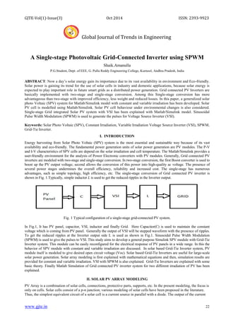
1. GJTE-Vol(1)-Issue(3) Oct 2014 ISSN: 2393-9923
Global Journal of Trends in Engineering
www.gjte.in 22
A Single-stage Photovoltaic Grid-Connected Inverter using SPWM
Shaik.Amanulla
P.G.Student, Dept. of EEE, G. Pulla Reddy Engineering College, Kurnool, Andhra Pradesh, India
ABSTRACT: Now a day’s solar energy gain its importance due to its vast availability in environment and Eco-friendly.
Solar power is gaining its trend for the use of solar cells in industry and domestic applications, because solar energy is
expected to play important role in future smart grids as a distributed power generation. Grid connected PV Inverters are
basically implemented with two-stage and single-stage conversion. Among this Single-stage conversion has more
advantageous than two-stage with improved efficiency, less weight and reduced losses. In this paper, a generalized solar
photo Voltaic (SPV) system for Matlab/Simulink model with constant and variable irradiation has been developed. Solar
PV cell is modelled using Matlab/Simulink. Solar PV cell behaviour under environmental changes is also considered.
Single-stage Grid integrated Solar PV system with VSI has been explained with Matlab/Simulink model. Sinusoidal
Pulse Width Modulation (SPWM) is used to generate the pulses for Voltage Source Inverter (VSI).
Keywords: Solar Photo Voltaic (SPV), Constant Irradiation, Variable Irradiation Voltage Source Inverter (VSI), SPWM,
Grid-Tie Inverter.
I. INTRODUCTION
Energy harvesting from Solar Photo Voltaic (SPV) system is the most essential and sustainable way because of its vast
availability and eco-friendly. The fundamental power generation units of solar power generation are PV modules. The P-V
and I-V characteristics of SPV cells are depend on the solar irradiation and cell temperature. The Matlab/Simulink provides a
user-friendly environment for the analysis of Power Electronic converters with PV modules. Generally, Grid connected PV
inverters are modeled with two-stage and single-stage conversion. In two-stage conversion, the first Boost converter is used to
boost up the PV output voltage; second allows the conversion of this power into high-quality ac voltage. The presence of
several power stages undermines the overall efficiency, reliability and increased cost. The single-stage has numerous
advantages, such as simple topology, high efficiency, etc. The single-stage conversion of Grid connected PV inverter is
shown in Fig. 1.Typically, simple inductor L is used to get the reduced ripples in the Inverter output.
Fig. 1 Typical configuration of a single-stage grid-connected PV system.
In Fig.1, It has PV panel, capacitor, VSI, inductor and finally Grid. Here Capacitor(C) is used to maintain the constant
voltage which is coming from PV panel. Generally the output of VSI will be stepped waveform with the presence of ripples.
To get the reduced ripples at the Inverter output side L is used as shown in Fig.1. Sinusoidal Pulse Width Modulation
(SPWM) is used to give the pulses to VSI. This study aims to develop a general purpose Simulink SPV module with Grid-Tie
Inverter system. This module can be easily reconfigured for the electrical response of PV panels in a wide range. In this the
behavior of SPV module with constant and variable irradiation are discussed. In solar based Grid-Tie Inverter system, PV
module itself is modeled to give desired open circuit voltage (Voc). Solar based Grid-Tie Inverters are useful for large-scale
solar power generation. Solar array modeling is first explained with mathematical equations and then, simulation results are
provided for constant and variable irradiation. VSI with SPWM is also explained. Grid-Tie Inverters are explained with some
basic theory. Finally Matlab Simulation of Grid connected PV inverter system for two different irradiation of PV has been
explained.
II. SOLAR PV ARRAY MODELING
PV Array is a combination of solar cells, connections, protective parts, supports, etc. In the present modeling, the focus is
only on cells. Solar cells consist of a p-n junction; various modeling of solar cells have been proposed in the literature.
Thus, the simplest equivalent circuit of a solar cell is a current source in parallel with a diode. The output of the current
2. GJTE-Vol(1)-Issue(3) Oct 2014 ISSN: 2393-9923
Global Journal of Trends in Engineering
www.gjte.in 23
source is directly proportional to the light falling on the cell (photocurrent). Thus, the diode determines the I–V
characteristics of the cell. The electrical equivalent circuit of a solar cell is shown in Fig. 2
Fig. 2 Solar cell electrically equivalent circuit
The output current I and the output voltage of a solar cell are given by
I =Iph− Ido – Vdo/Rsh (1)
=Iph−Io*(exp (q.Vdo/n.k.T) −1) −Vdo/Rsh (2)
V=Vdo−Rs*I (3)
Here, Ipv is the photocurrent, I0 is the reverse saturation current, Id0 is the average current through the diode, n is the
diode factor, q is the electron charge (q = 1.6˟10−19), k is the Boltzmann’s constant (k = 1.38∗10−23), and T is the solar
array panel temperature. Rs, the intrinsic series resistance of the solar cell; this value is normally very small. Rsh is the
equivalent shunt resistance of the solar array, and its value is very large. In general, the output current of a solar cell is
expressed by
I= Iph−Io*(exp (q*(V+Rs*I)/n.k.T) −1) –(V+Rs*I)Rsh (4)
In the above equation, the resistances can be generally neglected, and thus, it can be simplified to
I=ph−Io*(exp (q*V/n.k.T)−1) (5)
If the circuit is shorted, the output voltage V = 0, the average current through the diode is generally neglected, and the
short circuit current Isc is expressed by using
Isc=I= Iph−Ido− (Vdo/Rsh) (6)
Finally, the output power P is expressed as below,
P=V*I=V*(Iph−Ido−Vdo/Rsh) (7)
The below table is having the parameters and its values, which are used in the equivalent circuit of PV. To maximize the
short circuit current to 9.4A, 2PV panels are connected in parallel. The following parameters are useful to design Matlab
code with above equations, which is shown in Table1.
Table1. PV panel parameters used in simulation
Parameter Value
Short circuit Current(A) Isc=4.7
Open circuit Voltage(V) Voc=230
Shunt Resistance(Ω) Rsh=2000
Series Resistance(Ω) Rse=0.25
Amps/Kelvin(A/k) Ki=78*10-6
Volts/Kelvin(V/k) Kv=2.3*10-6
Temperature(°C) T=25
Diode factor n=1.3
Series connected cells Ns=384
The National Renewable Energy Laboratory (NREL) in their technical report used Matlab/Simulink since it presents
unique capabilities for developing control algorithms and power electronics modeling. In the research for a platform to
model a PV array or cell, many different programs were proposed but at the end the choice was clear in that
Matlab/Simulink and Simpowersystems would be the ideal modeling system since it offered accurate computations and
eased up on the power system block diagram design. Solar cell is acts as current source, so current source is taken from
Simpowersystems. Irradiation (insolation) and Temperature are taken as the input parameters for the panel. Generally
irradiation can be varied from 100W/m² to 1000W/m². The standard temperature condition (STC) for the panel is taken
as 25°c (298kelvins). For an ideal PV cell Rs is negligible and Rsh will be infinite but in a practical solar cell series
resistance (Rs) is taken as small and shunt resistance (Rsh) is taken as large.
A. PV cell characteristics under Constant Irradiation(constant insolation)
As shown in Fig.3 signal1 is having constant irradiation profile with 1000W/m² Irradiation. Here temperature is also
constant with 25°c.
3. GJTE-Vol(1)-Issue(3) Oct 2014 ISSN: 2393-9923
Global Journal of Trends in Engineering
www.gjte.in 24
Fig. 3 Constant irradiation profile with 1000 W/m² Irradiation.
When the irradiation profile with 1000W/m² is applied to the PV, the following Power-Voltage and Current-Voltage
characteristics are obtained. Here Voc=230V, Isc=9.4A and T=25°c (Standard Temperature condition). P-V and I-V
characteristics of PV are shown in Fig. 4.
Fig. 4 P-V and I-V characteristics of PV module with 1000W/m² irradiation.
From the Simulation results, it can observe that Vmax= 200V and Imax=8.5A and Pmax is around 1700W. These values
are useful to determine the Maximum Power Point (MPP). Pmax= Vmax*Imax. These values can be changed by solar
irradiation and cell temperature. In this paper, we can see how above parameters are changed during Variable irradiation.
Irradiation (insolation) will not be constant in practical world. Irradiation will be moderate in morning and evening times
and maximum during mid-day. If the irradiation is maximum, then we have maximum open circuit voltage and if the
irradiation is minimum, then we will have less open circuit voltage compare to previous.
B. PV cell characteristics under Variable Irradiation(Variable insolation)
As shown in Fig.5 signal2 is having variable irradiation profile with 600W/m² to1000W/m² Irradiation with Trapezoidal
signal. Here temperature is constant with 25°c (STC).
Fig. 5 Variable Irradiation profile with 600 W/m² to 1000 W/m².
The corresponding P-V and I-V characteristic of above irradiation profile is given below Fig. 6.
Fig. 6.P-V and I-V characteristics of PV module with 600W/m² to 1000W/m² irradiation.
From the Simulation results, it can observer that Vmax=210V, Imax= 7A and Pmax is around 1480W. Hence we can say
that PV module can be changed by the Irradiation changes. Vmax, Imax and Pmax are changed from previous one. PV
cell can also be changed by temperature but it is not considered here.
4. GJTE-Vol(1)-Issue(3) Oct 2014 ISSN: 2393-9923
Global Journal of Trends in Engineering
www.gjte.in 25
III. VOLTAGE SOURCE INVERTER MODEL
Fig. 7 Three phase-VSI
Three-phase VSI is shown in Fig. 7. Normally 180° mode of operation is preferred over 120° mode of operation due to it
better utilization of switches. In 180° mode of operation, there are six modes of operation in a cycle and the duration of
each mode is 60°. To avoid the short circuit in any mode switches are on without conducting in same leg. If S1 is ON,
then S4 will be OFF and if S3 is OFF, and then S6 will be ON. Here logic 1 is taken when switch is ON and logic 0 is
taken when switch is OFF. In mode1 and mode8, all upper leg switches are OFF and ON respectively. So there is no
output Voltage. From mode2 to mode6, we will have +Vdc and –Vdc which is explained in Table2.
Table2.Switching operations of VSI with 180° mode
mode S
1
S
3
S
5
S
4
S
6
S
2
Van Vbn Vcn Va
b
V
bc
Vca
mode1 0 0 0 1 1 1 0 0 0 0 0 0
mode2 1 0 0 0 1 1 2/3 -1/3 -1/3 1 0 -1
mode3 1 1 0 0 0 1 1/3 1/3 -2/3 0 1 -1
mode4 0 1 0 1 0 1 -1/3 2/3 -1/3 -1 1 0
mode5 0 1 1 1 0 0 -2/3 1/3 1/3 -1 0 1
mode6 0 0 1 1 1 0 -1/3 -1/3 2/3 0 -1 1
miode7 1 0 1 0 1 0 1/3 -2/3 1/3 1 -1 0
mode8 1 1 1 0 0 0 0 0 0 0 0 0
In above table, Van, Vbn and Vcn are pole voltages. Vab, Vbc and Vca are line voltages. When upper leg switch is ON,
then Pole Voltage will be 2/3Vdc. If lower leg switch is ON, then Pole Voltage will be -1/3Vdc. Line Voltages are
calibrated as given below,
Vab= Van-Vbn
Vbc=Vbn-Vcn
Vca=Vcn-Van
They are various techniques to vary the inverter gain. The most effective method of controlling gain and output voltage is
to incorporate Pulse Width Modulation (PWM) control within the inverters. Sinusoidal Pulse Width Modulation
(SPWM) is one of the PWM techniques. In this method, there are three sinusoidal reference waves each shifted by 120°.
A carrier wave is compared with the reference signal corresponding to a phase to generate the gating signals to that
phase. Comparing the carrier signal Vcr with the reference phases Vra, Vrb and Vrc produces the gating pulses g1, g3
and g5 for the switches S1, S3 and S5 respectively, as shown in Fig. 8. The instantaneous line-to-line voltage is Vab=
Vs*(g1-g3). The output voltage Vab is generated by eliminating the condition that two switches in the same arm cannot
operate at the same time.
5. GJTE-Vol(1)-Issue(3) Oct 2014 ISSN: 2393-9923
Global Journal of Trends in Engineering
www.gjte.in 26
Fig. 8 SPWM for VSI.
The phase-voltages (Van, Vbn, and Vcn) are identical, but 120° out of phase without even harmonics; moreover,
harmonics at frequencies multiple of three are identical in amplitude and phase in all phases.
IV. GRID-TIE INVERTER
Generally, Grid-Tie Inverter (GTI) is a power converter that converts direct current (DC) to alternating current (AC) with
ability to synchronize to interface with a utility line. The GTI must synchronize its frequency with that of the grid (e.g.
50 Hz) using a local oscillator and limit the voltage to no higher than the grid voltage. A high-quality modern GTI has a
fixed unity power factor, which means its output voltage and current are perfectly lined up. As we already discussed in
Introduction, Grid connected PV Inverters are implemented with single-stage than two-stage due to its reliability and
simple topology. In developed countries like United States and Germany are implementing this type of Grids with PV. In
this paper, simple inductor L is used to reduce the ripples in Inverter output. Capacitor is placed across the inverter input
side to maintain PV voltage as constant. The overall Matlab simulation setup for Grid connected PV Inverters are
explained as follows.
V.SIMULATION WORK
The Matlab simulation set up is shown in Fig. 9. It is consist of PV and Capacitor to the input side of Inverter.
PV with equivalent circuit is designed with Irradiation and Temperature as input parameters. The gate pulses are
generated by SPWM technique. An Inductor with parasitic resistance was added to give approximate sinusoidal output of
inverter. Three-phase load is connected across the inverter and then, it is fed to the infinite bus bar (GRID). Pi-section is
also added between load and Grid. Here Active and Reactive power blocks are also added to observe the Active and
Reactive powers before and after load. Here phase to phase Rms values of load and grid are selected as same as inverter
to observe the accurate results.
Fig. 9 Grid connected PV Inverter with simulation set up in Matlab.
6. GJTE-Vol(1)-Issue(3) Oct 2014 ISSN: 2393-9923
Global Journal of Trends in Engineering
www.gjte.in 27
A. The following simulation results are related to Grid connected PV with Irradiation 1000W/m².
Fig. 10.PV and Inverter output waveforms.
.
Fig. 11 Inverter phase currents and voltages waveforms before and after Load (GRID).
Fig. 12 Active and Reactive power waveforms before and after load.
In practical environment irradiation is not going to be constant throughout the day. In morning and evening sessions, it
will be moderate. Irradiation will be high during afternoon session. The average irradiation throughout the day will be
600W/m², but not 1000W/m².
B. The following simulation results are related to PV with grid-inverter with irradiation of 600W/m².
Fig. 13.PV and Inverter output waveforms.
7. GJTE-Vol(1)-Issue(3) Oct 2014 ISSN: 2393-9923
Global Journal of Trends in Engineering
www.gjte.in 28
Fig. 14.Inverter phase voltage and current waveforms before and after load (GRID).
Fig. 15.Active and Reactive power waveforms before and after load.
PV Panel output voltage can be varied by varying the external load connected to the PV. PV panel current and
power can be varied by varying the Irradiation. Hence there is a change in PV output current but not in PV output
voltage. The simulation results shows, there is a change in Active and Reactive powers before and after the load. If we
change the load then there will be change in PV output voltage. Here Irradiation is varied, so there is change in PV
current and power. There by active and reactive powers are changed with reduced manner which are shown Fig. 15 (after
load) when compared with Fig. 12 (before load). This Simulink model not uses transformer so it can be called as
Transformer less Grid-connected PV inverter. This is advantageous than Grid-connected PV inverters with transformers.
VI. CONCLUSION
This paper studies about the PV simulation under constant and variable irradiation. PV with grid-tie inverter system is
simulated for different irradiation. This PV system has been studied about the PV output voltages and currents with
different irradiation profiles. Also this system will be useful to simulate the high rated grids with PV. This system is
closely related to single-stage conversion of solar power without tracking Maximum Power Point from PV panel. Single-
stage conversion has several advantages than two-stage conversion without including Boost-converter. This can be
further extended to improved Grid connected PV Inverters with single-stage topology.
REFERENCES
[1] GMT Research, “U.S. solar market insight: 2010 year in review,” Solar Energy Industries Association, Washington,
D.C., 2010.
[2] Sera, S; Teodoresu, R.; Rodriguez.: PV panel model based on datasheet values, IEEE international Symposium on
Industrial Electronics, ISIE 2007, 4-7, Pp. 2392-2396, June 2007.
[3] S. Liu, R.A. Dugal, Dynamic Multiphysics Model for Solar Array, IEEE Trans. On Energy Conversion, Vol. 17, No.
2, Pp. 285-294, June 2002.
[4] E. Roman, R. Alonso,, P. Ibanze, S.Elorduizapatarietxe, and D. Goitia, “Intelligent PV module for grid-connected
PV systems , IEEE trans. Ind. Electron., Vol. 53, No. 4, Pp. 1066-1073, June 2006.
8. GJTE-Vol(1)-Issue(3) Oct 2014 ISSN: 2393-9923
Global Journal of Trends in Engineering
www.gjte.in 29
[5] Mohammad Ahmad and B. H. Khan, “Evaluation of New Grid connected Solar Inverter”, Aligarh Muslim
Technical University.
[6] Marcelo G. Molina, and Luis E. Juanico, “Dynamic modeling and control design of advanced photovoltaic solar
system for distributed generation applications”, Journal of Electrical Engineering, Vol.1, Issue. 3, Pp. 141-150,
2010.
[7] A. F. Williams, The hand book of Photo Voltaic applications: Building Applications and System design
considerations. Atlanta, GA: Fairmont Press., 1986.
[8] Sung-Hun Ko and Seong- Ryong Lee Hooman Dehbonei and C. V Nayar, ― A grid connected photovoltaic system
with direct coupled power quality control‖ Conference on IEEE Industrial Electronics, IECON 2006, pp. 5203-5208.
[9] Ryan C. Campbell. A circuit-based Photovoltaic Array model for Power system studies.
[10]M.P.Kazmierkowski, and L.Malesani, “Current control techniques for three-phase voltage-source PWM converters:
A Servey”, IEEE Transactions on Industrial Electronics, Vol. 45, No. 5, pp. 691-703, October 1998.
[11]W. Xiao.M. G. J. Lind W. G. Dunford, and A. Capel, “Real-time identification of optimal operating points in
photovoltaic power systems,” IEEE Trans. Ind. Electron. , Vol. 53, No. 4, pp. 1017-1026, June 2006.
Biography
Shaik Amanulla was completed his B.Tech in electrical and electronics engineering from KORM engineering college,
kadapa, A.P. in the year 2012. He is doing his post graduation study in G Pulla Reddy Engineering College, Kurnool
with specialization in Power Electronics. His area of research includes renewable energy systems and Power electronic
converters. Email id- aman.gprec@gmail.com.