Downloaded 801 times
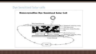
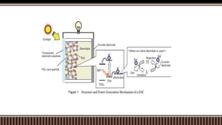

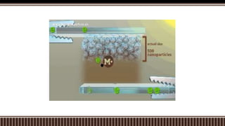


Dye sensitized solar cells (DSSCs) were invented by Brian O'Regan and Michael Gratzel at UC Berkley as a low-cost alternative to thin film solar cells. DSSCs consist of four main components: a semiconducting electrode like TiO2, a dye sensitizer that absorbs sunlight, a redox mediator like I-/I3- to restore the dye, and a counter electrode. When sunlight is absorbed by the dye, electrons are injected into the conduction band of the oxide and transported through an external circuit to the counter electrode, while the dye is regenerated by the redox mediator. Though less efficient than other solar cells currently, DSSCs offer a cheaper price


