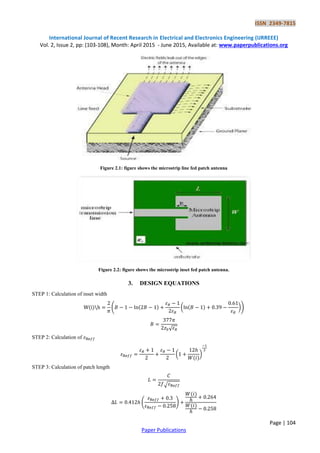
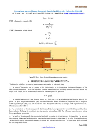
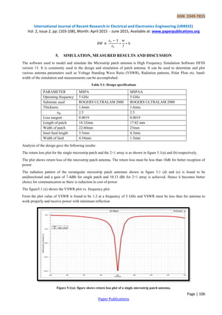
Abstract: Recently due to decrease in the size of communication devices there is a need for more compact antenna. Microstrip antenna is popularly known as patch antenna, which fulfils this need. It consists of metal patch on one side of the dielectric substrate and ground plane on the other side. The metal patch is generally etched on the substrate and takes a variety of continuous shapes such as rectangle, circular, elliptical, square etc.
1. ISSN 2349-7815
International Journal of Recent Research in Electrical and Electronics Engineering (IJRREEE)
Vol. 2, Issue 2, pp: (103-108), Month: April 2015 - June 2015, Available at: www.paperpublications.org
Page | 103
Paper Publications
Design of Micro Strip Patch Antenna Array
Lakshmi Prasanna1
, Shambhawi Priya2
, Sadhana R.H. 3
, Jayanth C 4
Department of Telecommunication Engineering (DSCE), Bangalore-560078, India
Abstract: Recently due to decrease in the size of communication devices there is a need for more compact antenna.
Microstrip antenna is popularly known as patch antenna, which fulfils this need. It consists of metal patch on one
side of the dielectric substrate and ground plane on the other side. The metal patch is generally etched on the
substrate and takes a variety of continuous shapes such as rectangle, circular, elliptical, square etc.
Keywords: Micro strip patch antenna.
1. INTRODUCTION
Due to the continued demand for low cost, less weight, highly reliable, minimal profile antennas for air borne vehicles, it
poses a new challenge for the design of antenna in radar communications. In recent years there is a need for more compact
antennas due to rapid decrease in size of communication devices.
Microstrip patch antennas were first proposed in early 1970s and since then activity in this area of antenna engineering
has occurred, probably more than in any other field of antenna research and development. Microstrip patch antennas have
various well known advantages over other antenna structures. Due to these merits, the microstrip patch antennas have
been utilized in many applications such as mobile communication, space borne satellite communication systems,
telemetry and radar applications.
2. FEEDING TECHNIQUES
Micro-strip antenna can be fed by variety of methods. The feeding techniques in microstrip antenna can be broadly
classified as -
1. Contacting
2. Non-contacting
These can be further categorised as
i. Micro-strip line
ii. Co-axial probe
iii. Aperture coupling
iv. Proximity coupling
Antenna is a passive device and hence power must be fed for it to radiate. The feeding technique employed plays an
important role in the characteristics of the antenna. The feeding technique used in this design is a microstrip line feed. In
this feed technique impedence matching is difficult to achieve. Hence the microstrip line is “inset” in the patch. This
provides better impedence matching.
Microstrip inset feed technique is adopted to reduce the input impedence and provide better matching.
2. ISSN 2349-7815
International Journal of Recent Research in Electrical and Electronics Engineering (IJRREEE)
Vol. 2, Issue 2, pp: (103-108), Month: April 2015 - June 2015, Available at: www.paperpublications.org
Page | 104
Paper Publications
Figure 2.1: figure shows the microstrip line fed patch antenna
Figure 2.2: figure shows the microstrip inset fed patch antenna.
3. DESIGN EQUATIONS
STEP 1: Calculation of inset width
( ( ))
√
STEP 2: Calculation of
( )
STEP 3: Calculation of patch length
√
( )
3. ISSN 2349-7815
International Journal of Recent Research in Electrical and Electronics Engineering (IJRREEE)
Vol. 2, Issue 2, pp: (103-108), Month: April 2015 - June 2015, Available at: www.paperpublications.org
Page | 105
Paper Publications
STEP 4: Calculation of patch width
√
STEP 5: Calculation of inset length
( )
Figure 3.1: figure shows the inset fed patch antenna parameters
4. DESIGN GUIDELINES FOR PATCH ANTENNA
The following guidelines are must for designing patch antenna fed by Microstrip lines:
1. The length of the patches may be changed to shift the resonances to the centre of the fundamental frequency of the
individual patch elements. This is true in general, even for more complicated microstrip antennas that weave around the
length of the longest path on the microstrip controls the lowest frequency of operation.
√
2. The resonant input resistance and radiation pattern of a single patch can be decreased by increasing the width of the
patch. The wider the patch becomes the lower the input impedance. This is acceptable as long as the ratio of the patch
width to patch length does not exceed two; since the aperture efficiency of a single patch begins to reduce as,
increases beyond two.
3. The permitivity of the substrate controls the fringing fields. Lower permitivities have wider fringes and therefore
better radiation. Reducing the permittivity also increases the antenna bandwidth. The efficiency is also improved with a
lower value for the permitivity.
4. The height of the substrate also controls the bandwidth increasing the height increases the bandwidth. The fact that
increasing the thickness of a patch antenna improves its bandwidth can be understood by recalling the general rule that
“an antenna occupying more space in a spherical volume will have a wider bandwidth”. Increase in the height increases
the efficiency of the antenna.
4. ISSN 2349-7815
International Journal of Recent Research in Electrical and Electronics Engineering (IJRREEE)
Vol. 2, Issue 2, pp: (103-108), Month: April 2015 - June 2015, Available at: www.paperpublications.org
Page | 106
Paper Publications
5. SIMULATION, MEASURED RESULTS AND DISCUSSION
The software used to model and simulate the Microstrip patch antenna is High Frequency Simulation Software HFSS
version 13. It is commonly used in the design and simulation of patch antenna. It can be used to determine and plot
various antenna parameters such as Voltage Standing Wave Ratio (VSWR), Radiation patterns, Polar Plots etc. band-
width of the simulation and measurements can be accomplished.
Table 5.1: Design specifications
PARAMETER MSPA MSPAA
Operating frequency 5 GHz 5 GHz
Substrate used ROGERS ULTRALAM 2000 ROGERS ULTRALAM 2000
Thickness 1.6mm 1.6mm
2.5 2.5
Loss tangent 0.0019 0.0019
Length of patch 18.32mm 17.82 mm
Width of patch 22.60mm 23mm
Inset feed length 5.5mm 4.3mm
Width of feed 4.54mm 1.5mm
Analysis of the design gave the following results:
The return loss plot for the single microstrip patch and the 2×1 array is as shown in figure 5.1(a) and (b) respectively.
The plot shows return loss of the microstrip patch antenna. The return loss must be less than 10db for better reception of
power
The radiation pattern of the rectangular microstrip patch antennas shown in figure 5.1 (d) and (e) is found to be
unidirectional and a gain of 7.4dBi for single patch and 10.13 dBi for 2×1 array is achieved. Hence it becomes better
choice for communication as there is reduction in cost of power
The figure5.1 (e) shows the VSWR plot vs. frequency plot
From the plot value of VSWR is found to be 1.2 at a frequency of 5 GHz and VSWR must be less than for antenna to
work properly and receive power with minimum reflection
Figure 5.1(a): figure shows return loss plot of a single microstrip patch antenna.
5. ISSN 2349-7815
International Journal of Recent Research in Electrical and Electronics Engineering (IJRREEE)
Vol. 2, Issue 2, pp: (103-108), Month: April 2015 - June 2015, Available at: www.paperpublications.org
Page | 107
Paper Publications
Figure 5.1(b): figure shows return loss plot of a 2×1 microstrip patch antenna array.
Figure 5.1(c): figure shows radiation pattern of a single microstrip patch antenna.
Figure 5.1(d): figure shows radiation pattern of a 2×1 microstrip patch antenna array.
6. ISSN 2349-7815
International Journal of Recent Research in Electrical and Electronics Engineering (IJRREEE)
Vol. 2, Issue 2, pp: (103-108), Month: April 2015 - June 2015, Available at: www.paperpublications.org
Page | 108
Paper Publications
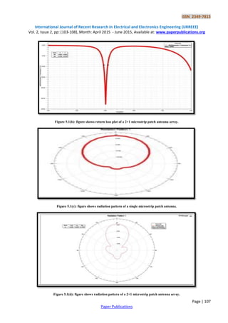
Figure 5.1(e): figure shows VSWR plot of a 2×1 microstrip patch antenna array.
6. CONCLUSION
In this work the microstrip patch antenna and 2×1 array are designed and its results are reported. The important
parameters such as gain, return loss, VSWR, and radiation pattern have been observed.
REFERENCES
[1] R. Garg, P. Bhartia, I. Bahl, and A. Ittipiboon, Microstrip Antenna Design Handbook, Artech House, 2000.
[2] C. A. Balanis, Antenna Theory, Analysis and Design, John Wiley & Sons, New York, 1997.
[3] D. M. Pozar and D. H. Schaubert, “Microstrip Antennas: The Analysis and Design of Microstrip Antennas and
Arrays”, IEEE Press, 1995