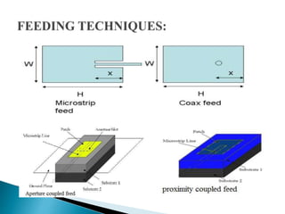
ANKIT KUMAR PANDEY
M.TECH (ELECTRONICS ENGG.)
J.K. INSTITUTE OF APPLIED PHYSICS & TECHNOLOGY
ALLAHABAD
 Antenna
 Micro strip antennas
• Introduction
• Types of patch geometries
• Feeding Techniques
• Advantages & Disadvantages
 Defected Ground Structure(DGS)
• Introduction
• Various DGSs
• Applications of DGSs
 Antenna is usually a metallic device for receiving and
radiating radio waves.
 According to IEEE standards antenna is a means of
radiating or receiving radio waves, it is a transitional
structure between free space and guided devices.
 It consists of a radiating metallic (gold,copper,silver)
patch on one side dielectric substrate which has a
ground plane on the other side.
 The radiating patch and feed lines are usually photo
etched on the dielectric substrate.
 The patch acts approximately as a resonant cavity (short
circuit walls on top and bottom, open-circuit walls on the
sides). If the antenna is excited at a resonant frequency, a
strong field is set up inside the cavity, and a strong
current on the surface of the patch. This produces
significant radiation.
There are four basic feeds used in micro strip antenna,
they are:
 Micro strip line feed
 Coaxial feed
 Aperture Coupled feed
 Proximity coupled feed
 Light weight and low volume
 Low fabrication cost
 Supports both linear as well as circular polarization
 Capable of dual and triple frequency operation
 Mechanically robust when mounted on rigid surfaces
 Narrow bandwidth
 Low efficiency
 Low gain
 Low power handling capacity
 Poor end fire radiator except tapered slot antenna.
 DGS is an etched periodic or non-periodic cascaded
configuration defect in ground of a planar
transmission line (e.g., micro strip) which disturbs the
shield current distribution in the ground plane cause
of the defect in the ground.
 This disturbance will change characteristics of a
transmission line such as line capacitance and
inductance.
 The basic element of DGS is a resonant gap or slot in the
ground metal, placed directly under a transmission line and
aligned for efficient coupling to the line.
 The equivalent circuit for a DGS is a parallel-tuned circuit in
series with the transmission line to which it is coupled.
(a) spiral head, (b) arrowhead-slot, (c) “H” shape slots, (d) a square open-loop
with a slot in middle section , (e) open-loop dumbbell and (f) inter digital
DGS.
Equivalent circuit of a DGS element. The values of L, C and R are
determined by the dimensions and location relative to the
“through” transmission line
 Delay lines: Placement of DGS resonators along a
transmission line introduce changes in the propagation of the
wave along the line. The DGS elements do not affect the odd
mode transmission, but slows the even mode, which must
propagate around the edges of the DGS “slot.”
 Antennas : The filtering characteristics of DGS can be applied
to antennas, reducing mutual coupling between antenna array
elements, or reducing unwanted responses (similar to filters).
To design the conventional rectangular micro strip patch antenna that operates at
frequency around 2.45GHz, the dimensions -
 Width (W) W = 37.26mm.
 Effective dielectric constant (εreff). εreff = 4.4.
 Effective length (Leff) The effective :Leff = 29.126 mm.
 Length extension (ΔL) = 0.01634 mm
 Actual length of patch (L): L = Leff -2ΔL= 29.093 mm
 The S-parameter plot of the MSA design is shown and from
the plot we can easily calculate the bandwidth as well as return
are at various frequencies & BW. Due to the presence of the
multiple bands as well as presence of so many numbers of
varying amplitudes this antenna will consume too much power
and hence will not radiate effectively on the particular selected
band.
The low band (2.5-2.69GHz), the middle band (3.2-3.8GHz) and the
upper band (5.2-5.8GHz).
 The cavity backed structure is an approach in which the
electric walls are placed surrounding the patch to avoid the
surface wave propagation and thus the efficiency is increased.
In the proposed antenna the two electric walls are placed along
the width o the patch and connected with the ground plane of
the antenna to avoid the surface wave propagation.
Antenna efficiency without DGS Antenna efficiency with DGS
The dimensions of the DGS cell are:
• a= 1.5 mm, b= 6.8 mm, and g=1.8 mm
• The proper feed position is taken 2 mm away from
the patch centre at the origin along the length.
 DGS has relocated frequency which made antenna compact &
less return loss.
 The effect of dumbbell shaped DGS cell upon the size of
micro strip antenna is shown and then the cavity backed model
is used for increasing the efficiency of the proposed antenna.
 The performance characteristics of the proposed
antenna(antenna with DGS) are well compared to the
conventional antenna.
 A DGS is proposed naturally as a technique of suppressing XP
radiation of a micro strip radiator.
 J.S. Lim, Y.T. Lee, J.H. han, J.S. Park, D. Ahn, S. Nam, "Application of defected
ground structure in reducing the size of amplifiers", IEEE microwave and wireless
component lett., Vol. 12, No.7, July 2002.
 D. Guha, M. biswas and Y.M.M. Antar, "Micro strip patch antenna with defected
ground structure for cross polarization suppression", IEEE antenna and wireless
propagation lett, Vol.4, pp.455-458, 2005.
 Constantine A. Balanis- Antenna Theory Analysis and Design, Second Edition,
John Wiley & Sons (Asia) Pte Ltd. ISBN 9971-51-233-5,2001.
 C. S. Kim, J. S. Park, D. Ahn and J. B. Lim, “An Improved 1-D Periodic Defected
Ground Structure for Micro strip Line,” IEEE Microwave and Wireless
Components Letters, Vol. 10, No. 4, 2004, pp. 180-182.
 F. Zavosh and James T. Aberle, "Improving theperformance of microstrip patch
antennas", IEEE Antenna and Propagation Magazine, Vol.38, No.4, pp. 712.
August 1996.

Microstrip patch antenna with DGS

  • 1.
    ANKIT KUMAR PANDEY M.TECH(ELECTRONICS ENGG.) J.K. INSTITUTE OF APPLIED PHYSICS & TECHNOLOGY ALLAHABAD
  • 2.
     Antenna  Microstrip antennas • Introduction • Types of patch geometries • Feeding Techniques • Advantages & Disadvantages  Defected Ground Structure(DGS) • Introduction • Various DGSs • Applications of DGSs
  • 3.
     Antenna isusually a metallic device for receiving and radiating radio waves.  According to IEEE standards antenna is a means of radiating or receiving radio waves, it is a transitional structure between free space and guided devices.
  • 4.
     It consistsof a radiating metallic (gold,copper,silver) patch on one side dielectric substrate which has a ground plane on the other side.  The radiating patch and feed lines are usually photo etched on the dielectric substrate.
  • 5.
     The patchacts approximately as a resonant cavity (short circuit walls on top and bottom, open-circuit walls on the sides). If the antenna is excited at a resonant frequency, a strong field is set up inside the cavity, and a strong current on the surface of the patch. This produces significant radiation.
  • 7.
    There are fourbasic feeds used in micro strip antenna, they are:  Micro strip line feed  Coaxial feed  Aperture Coupled feed  Proximity coupled feed
  • 9.
     Light weightand low volume  Low fabrication cost  Supports both linear as well as circular polarization  Capable of dual and triple frequency operation  Mechanically robust when mounted on rigid surfaces
  • 10.
     Narrow bandwidth Low efficiency  Low gain  Low power handling capacity  Poor end fire radiator except tapered slot antenna.
  • 11.
     DGS isan etched periodic or non-periodic cascaded configuration defect in ground of a planar transmission line (e.g., micro strip) which disturbs the shield current distribution in the ground plane cause of the defect in the ground.  This disturbance will change characteristics of a transmission line such as line capacitance and inductance.
  • 12.
     The basicelement of DGS is a resonant gap or slot in the ground metal, placed directly under a transmission line and aligned for efficient coupling to the line.  The equivalent circuit for a DGS is a parallel-tuned circuit in series with the transmission line to which it is coupled.
  • 13.
    (a) spiral head,(b) arrowhead-slot, (c) “H” shape slots, (d) a square open-loop with a slot in middle section , (e) open-loop dumbbell and (f) inter digital DGS.
  • 15.
    Equivalent circuit ofa DGS element. The values of L, C and R are determined by the dimensions and location relative to the “through” transmission line
  • 16.
     Delay lines:Placement of DGS resonators along a transmission line introduce changes in the propagation of the wave along the line. The DGS elements do not affect the odd mode transmission, but slows the even mode, which must propagate around the edges of the DGS “slot.”  Antennas : The filtering characteristics of DGS can be applied to antennas, reducing mutual coupling between antenna array elements, or reducing unwanted responses (similar to filters).
  • 18.
    To design theconventional rectangular micro strip patch antenna that operates at frequency around 2.45GHz, the dimensions -  Width (W) W = 37.26mm.  Effective dielectric constant (εreff). εreff = 4.4.  Effective length (Leff) The effective :Leff = 29.126 mm.  Length extension (ΔL) = 0.01634 mm  Actual length of patch (L): L = Leff -2ΔL= 29.093 mm
  • 19.
     The S-parameterplot of the MSA design is shown and from the plot we can easily calculate the bandwidth as well as return are at various frequencies & BW. Due to the presence of the multiple bands as well as presence of so many numbers of varying amplitudes this antenna will consume too much power and hence will not radiate effectively on the particular selected band.
  • 20.
    The low band(2.5-2.69GHz), the middle band (3.2-3.8GHz) and the upper band (5.2-5.8GHz).
  • 21.
     The cavitybacked structure is an approach in which the electric walls are placed surrounding the patch to avoid the surface wave propagation and thus the efficiency is increased. In the proposed antenna the two electric walls are placed along the width o the patch and connected with the ground plane of the antenna to avoid the surface wave propagation.
  • 22.
    Antenna efficiency withoutDGS Antenna efficiency with DGS The dimensions of the DGS cell are: • a= 1.5 mm, b= 6.8 mm, and g=1.8 mm • The proper feed position is taken 2 mm away from the patch centre at the origin along the length.
  • 23.
     DGS hasrelocated frequency which made antenna compact & less return loss.  The effect of dumbbell shaped DGS cell upon the size of micro strip antenna is shown and then the cavity backed model is used for increasing the efficiency of the proposed antenna.  The performance characteristics of the proposed antenna(antenna with DGS) are well compared to the conventional antenna.  A DGS is proposed naturally as a technique of suppressing XP radiation of a micro strip radiator.
  • 24.
     J.S. Lim,Y.T. Lee, J.H. han, J.S. Park, D. Ahn, S. Nam, "Application of defected ground structure in reducing the size of amplifiers", IEEE microwave and wireless component lett., Vol. 12, No.7, July 2002.  D. Guha, M. biswas and Y.M.M. Antar, "Micro strip patch antenna with defected ground structure for cross polarization suppression", IEEE antenna and wireless propagation lett, Vol.4, pp.455-458, 2005.  Constantine A. Balanis- Antenna Theory Analysis and Design, Second Edition, John Wiley & Sons (Asia) Pte Ltd. ISBN 9971-51-233-5,2001.  C. S. Kim, J. S. Park, D. Ahn and J. B. Lim, “An Improved 1-D Periodic Defected Ground Structure for Micro strip Line,” IEEE Microwave and Wireless Components Letters, Vol. 10, No. 4, 2004, pp. 180-182.  F. Zavosh and James T. Aberle, "Improving theperformance of microstrip patch antennas", IEEE Antenna and Propagation Magazine, Vol.38, No.4, pp. 712. August 1996.