Downloaded 1,314 times
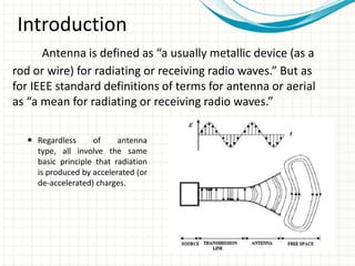

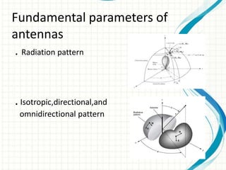
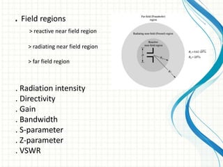
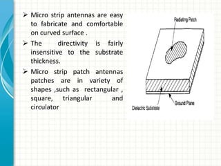
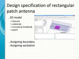
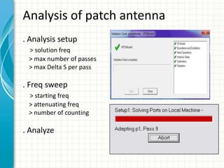
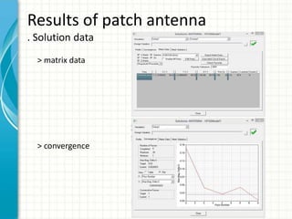
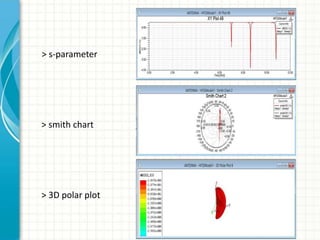
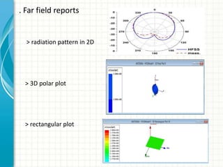


This document describes the design and analysis of a rectangular microstrip patch antenna. It discusses the fundamental parameters of antennas, defines a microstrip patch antenna and its properties. It then details the design specifications for the rectangular patch, including its 3D modeling in HFSS software. The results of simulating the patch antenna in HFSS are presented, including S-parameters, radiation patterns and far field reports. Advantages and disadvantages of microstrip patch antennas are listed, along with their applications. The conclusion discusses achieving better return loss, gain and efficiency for the designed patch antenna.