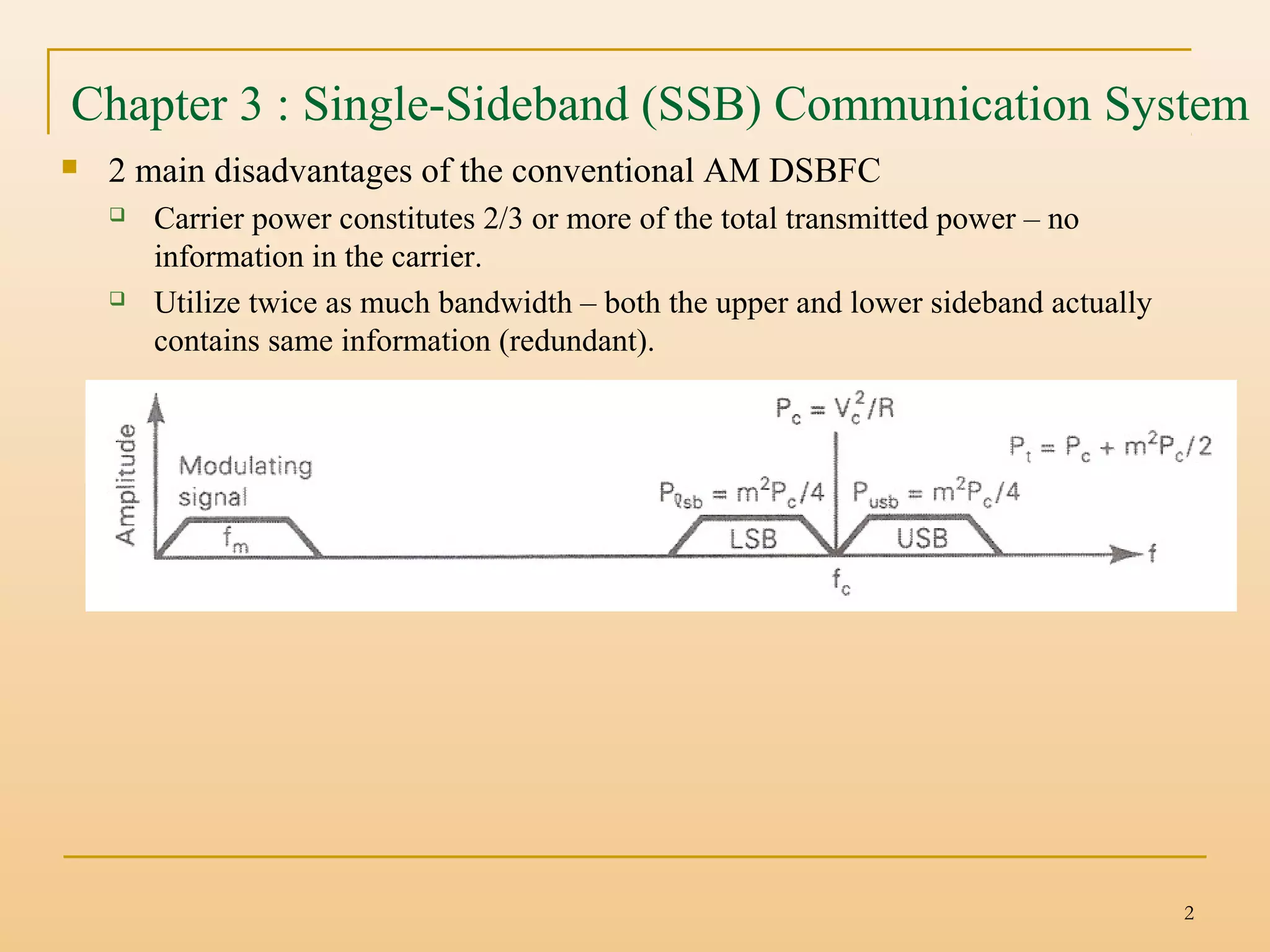
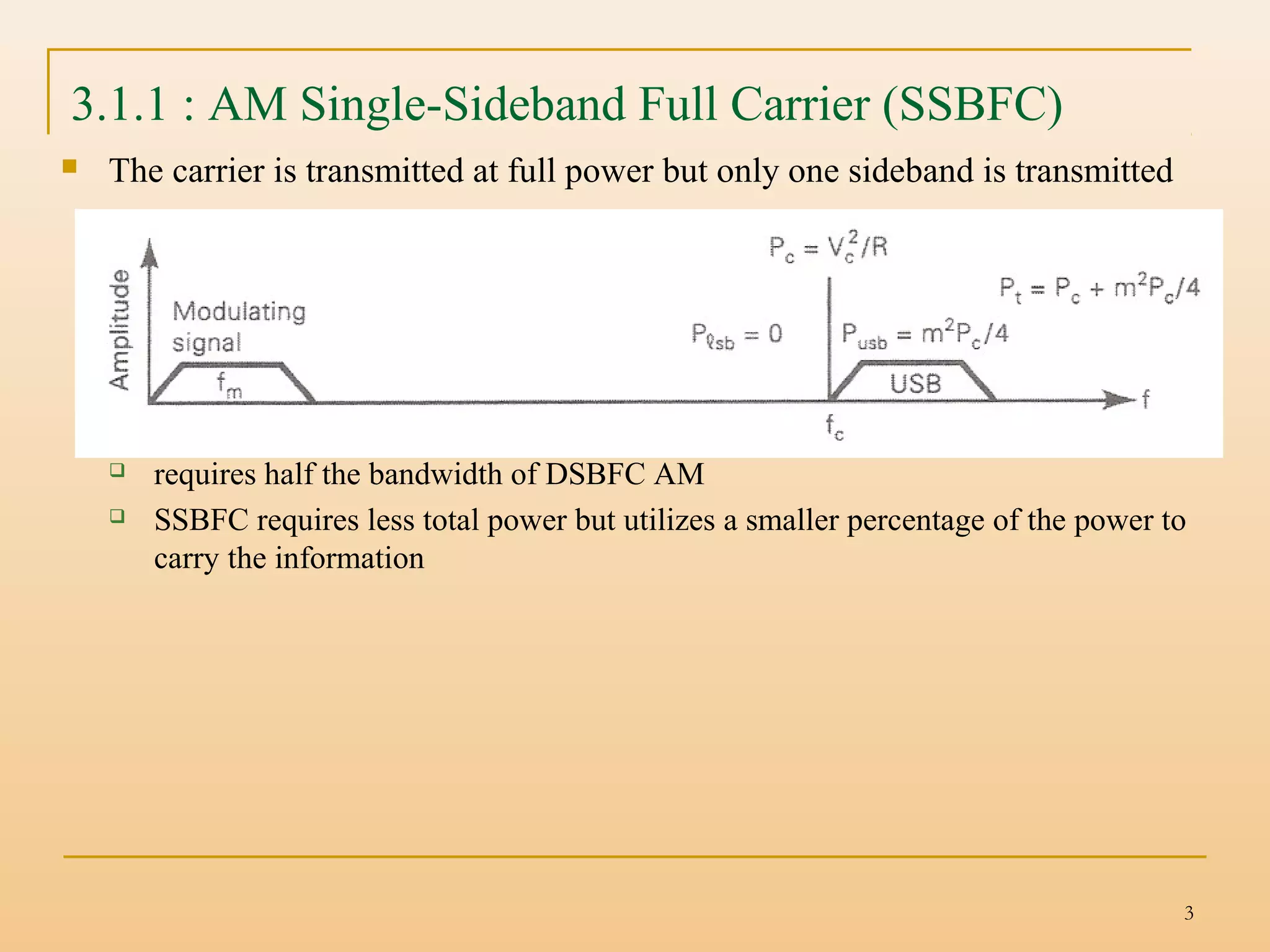
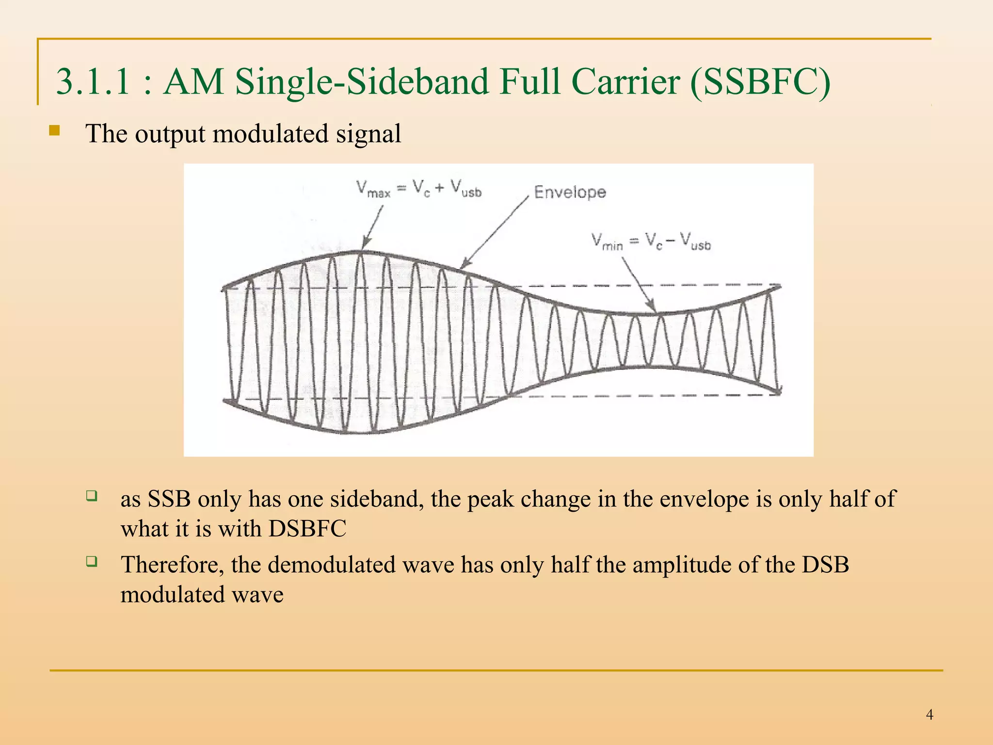
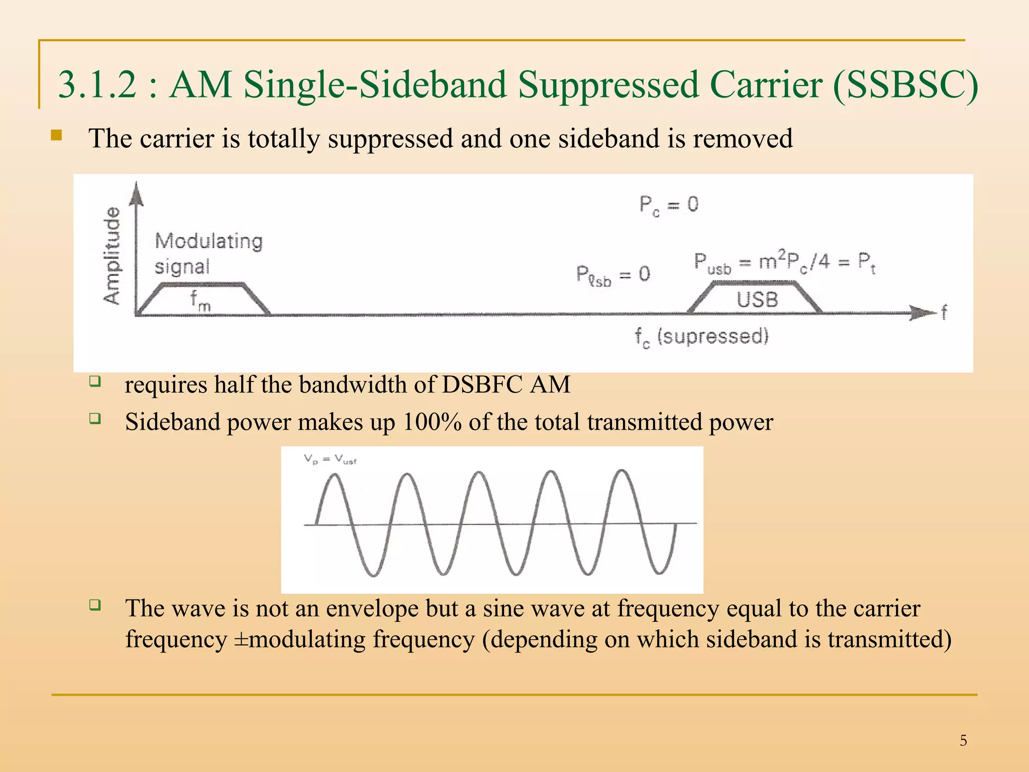
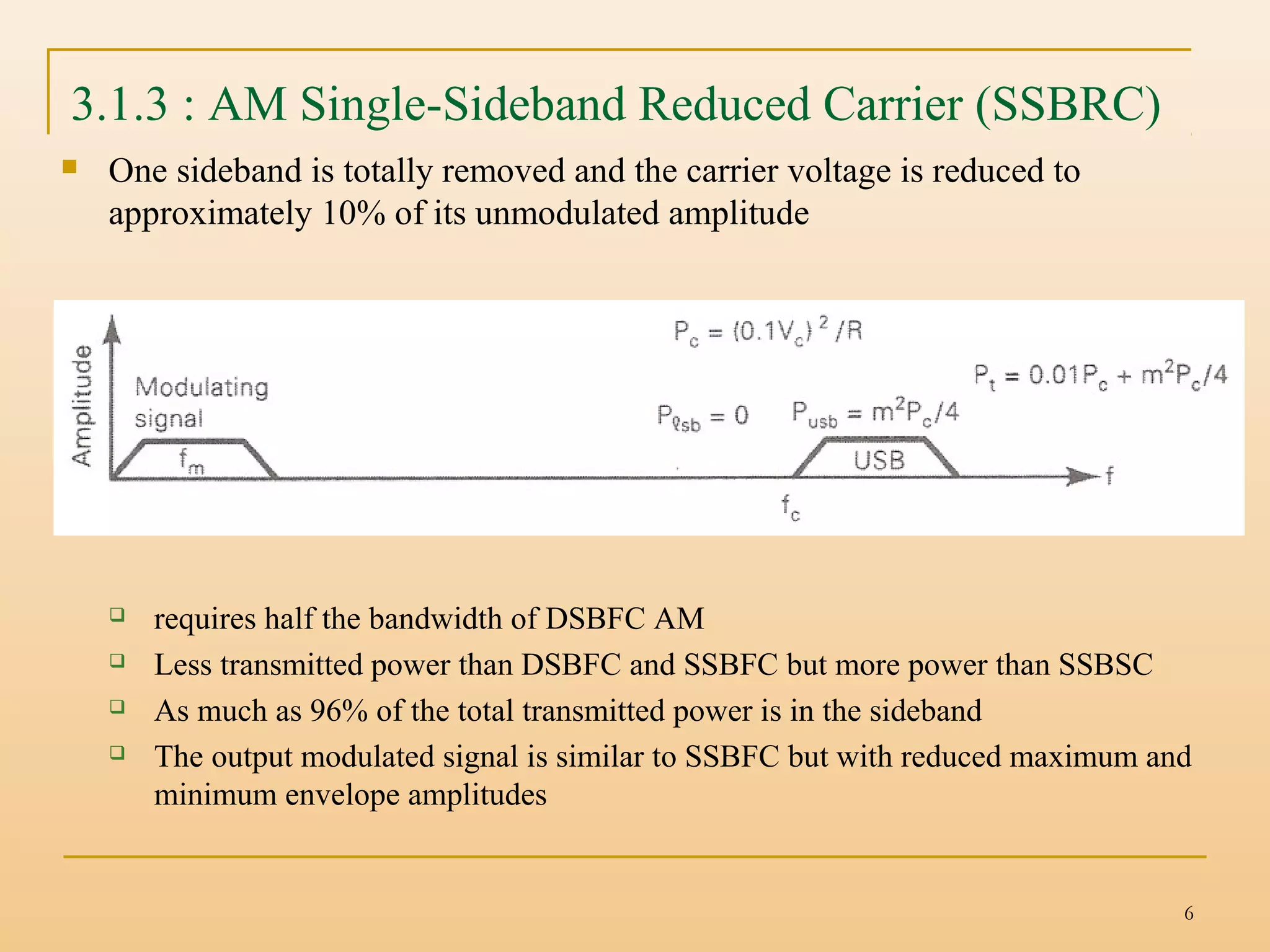
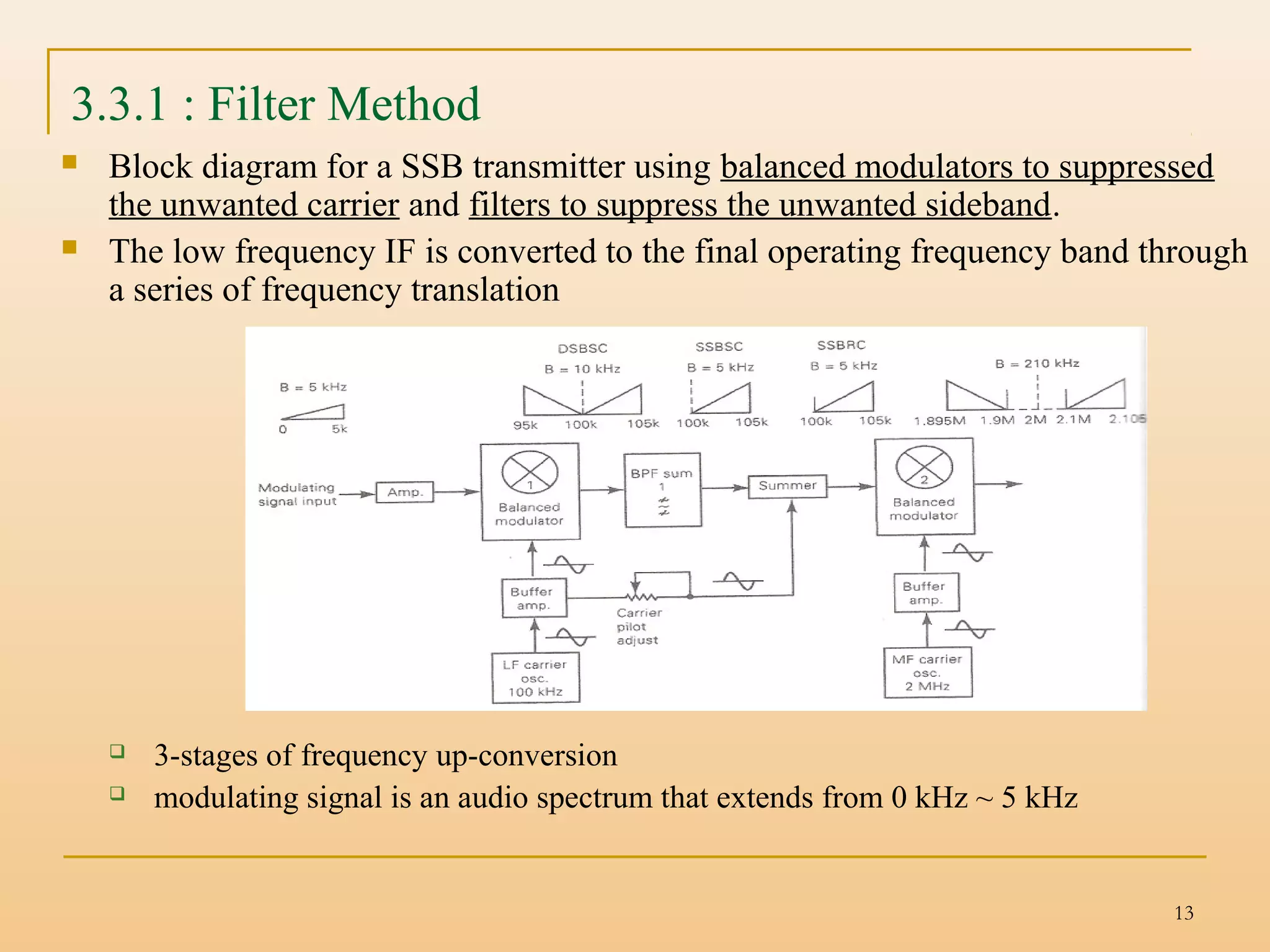
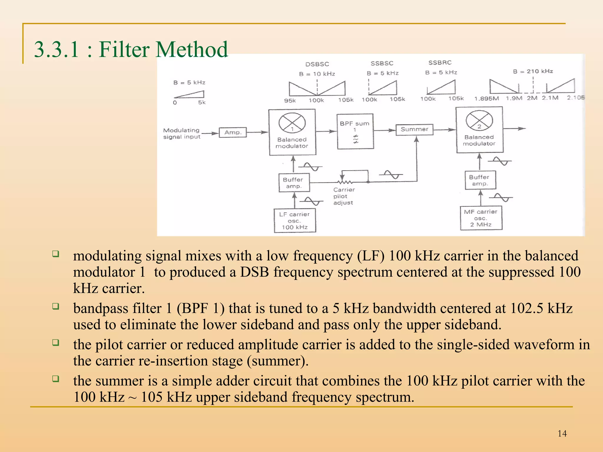
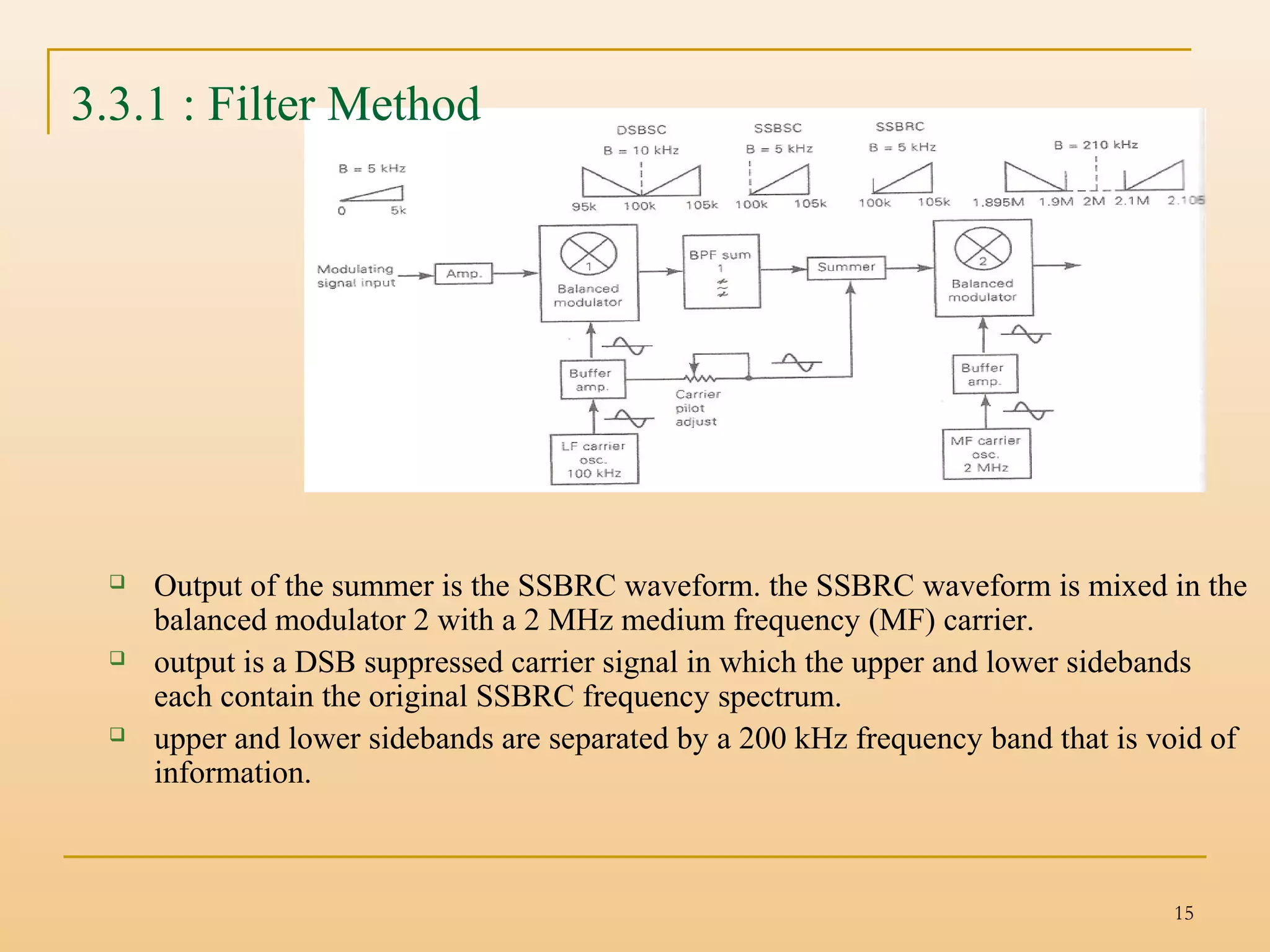
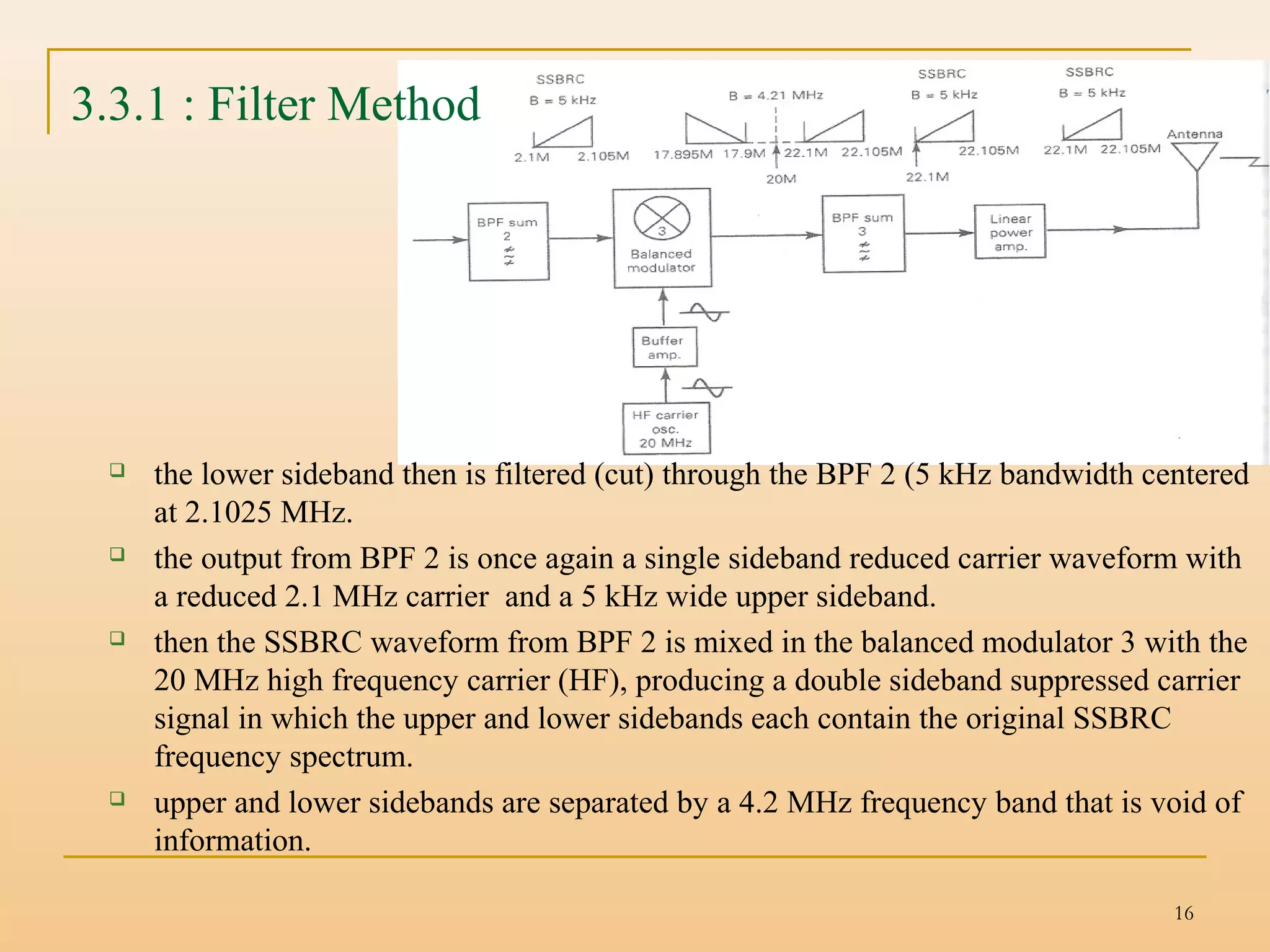
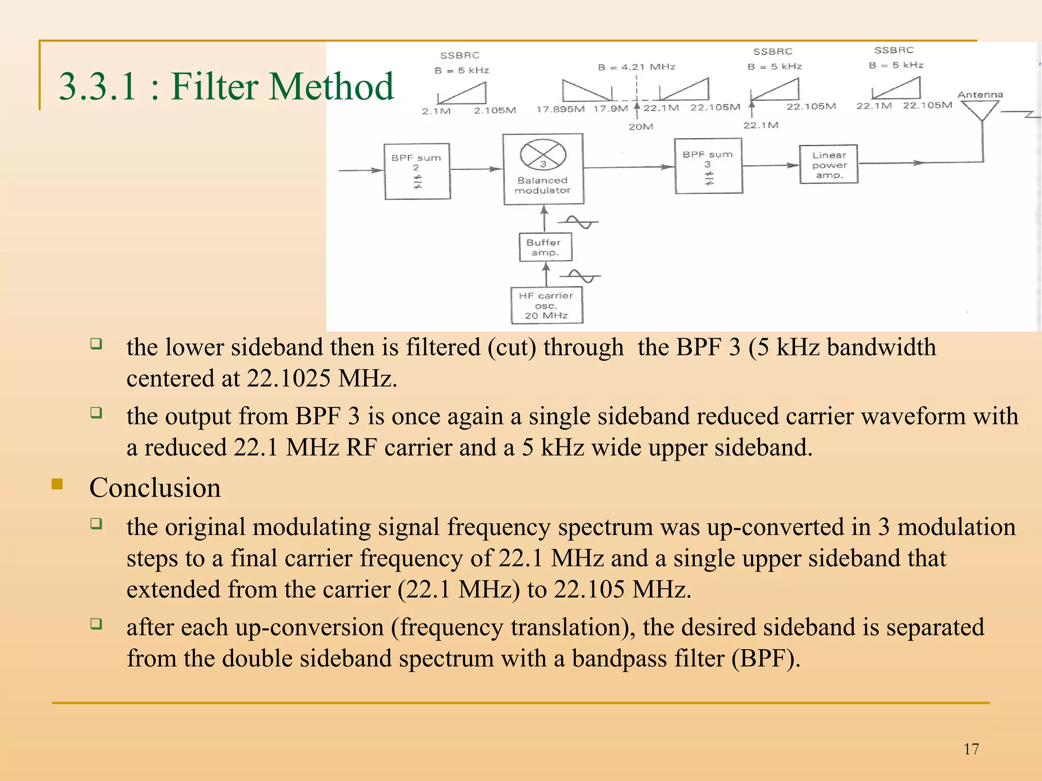
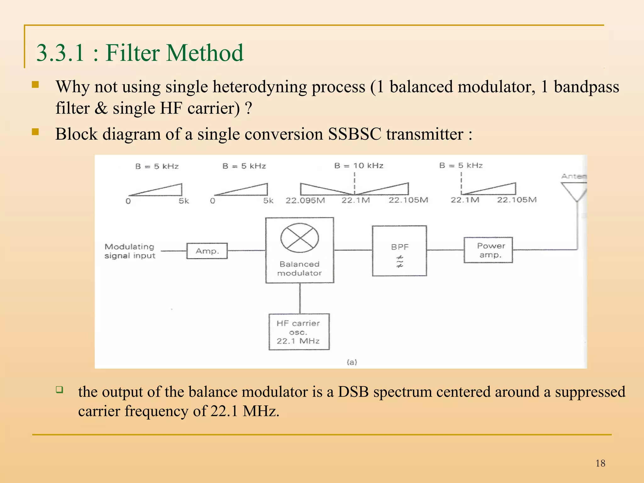
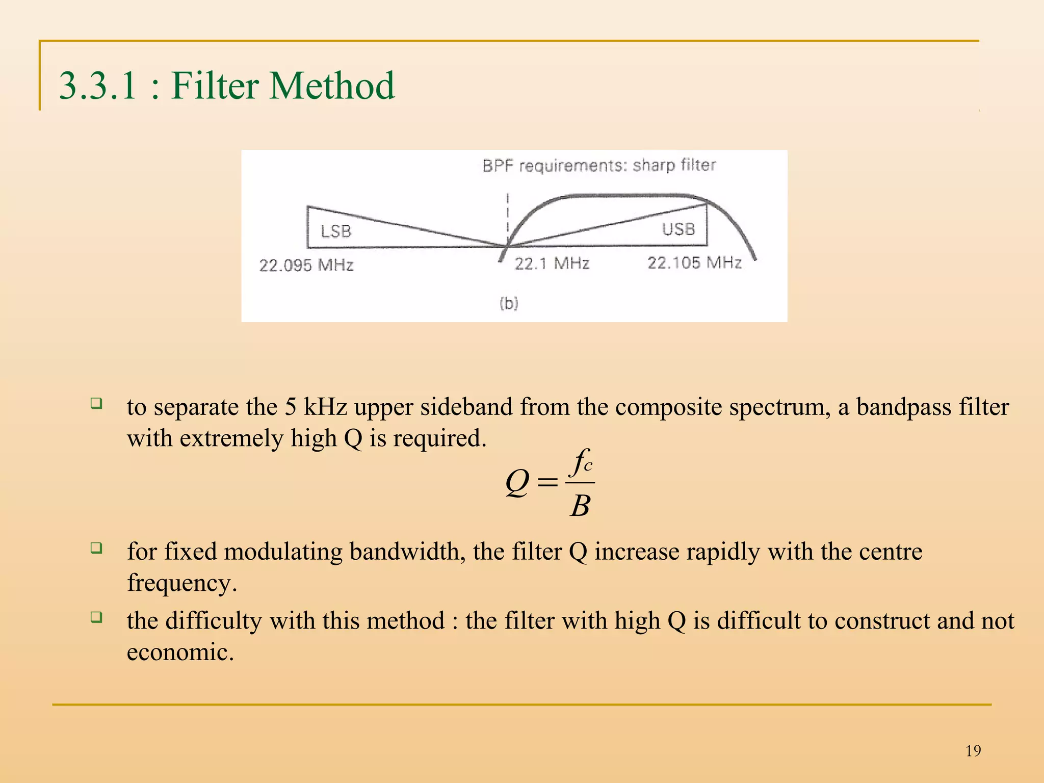
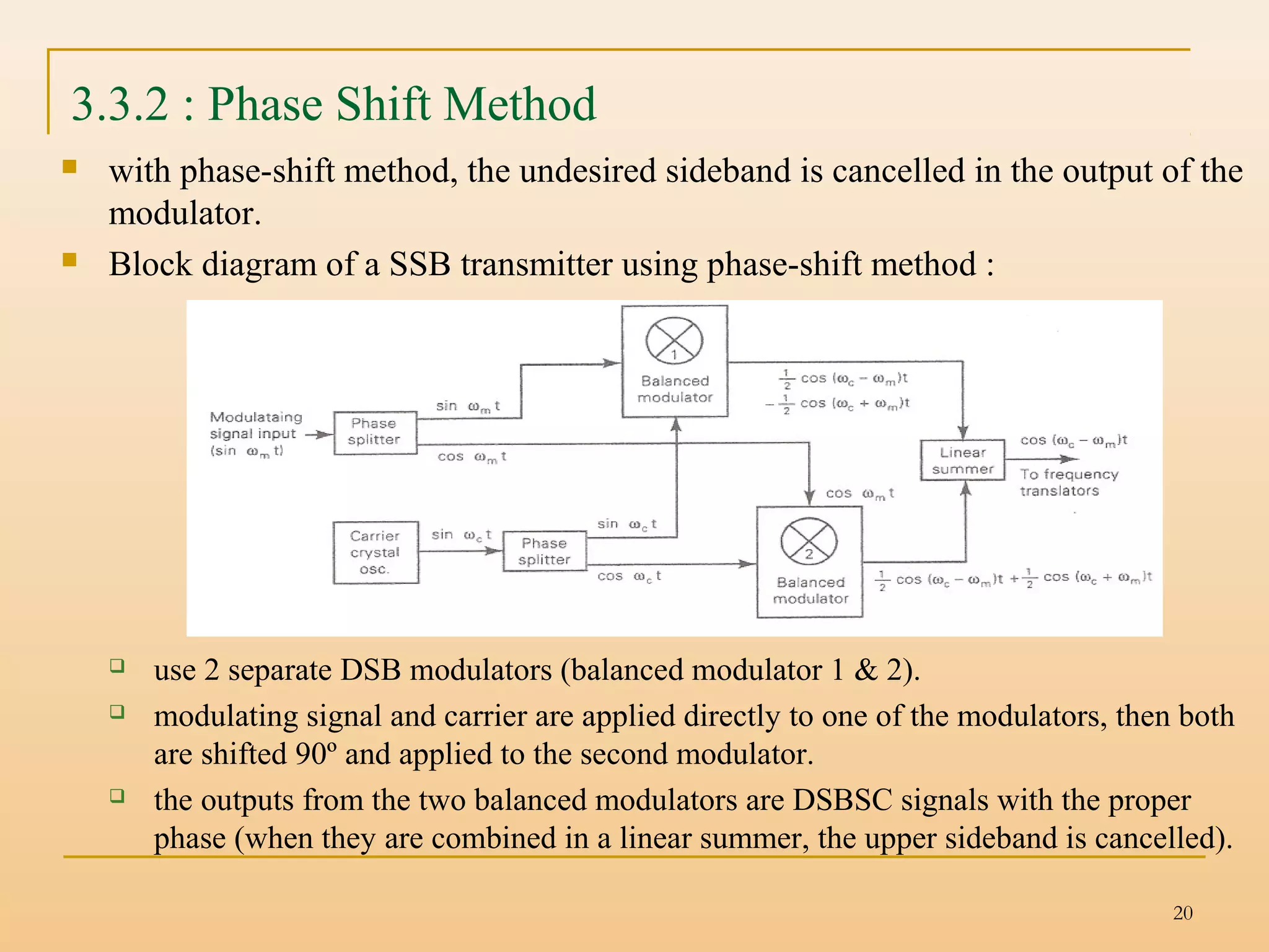
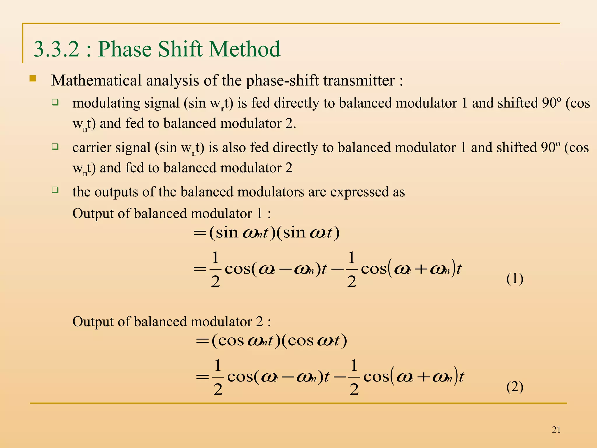
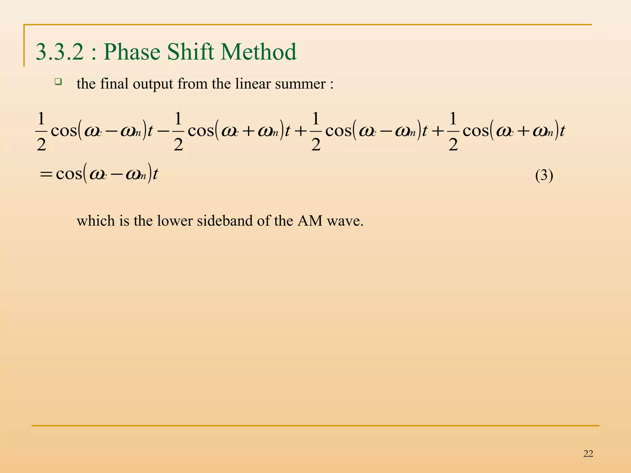
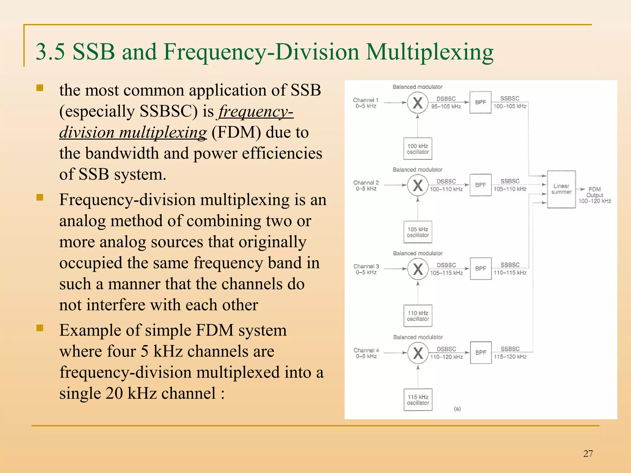
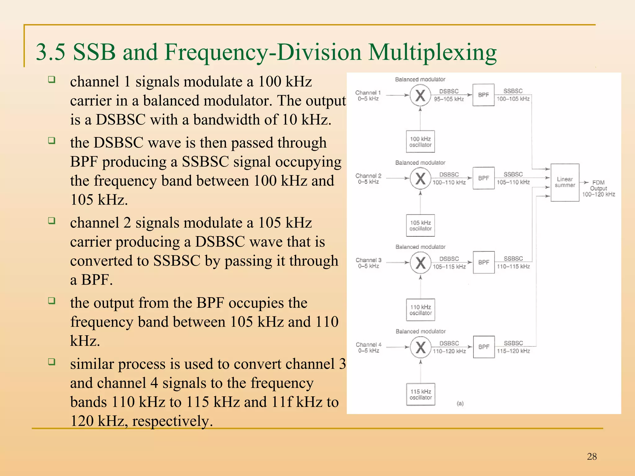
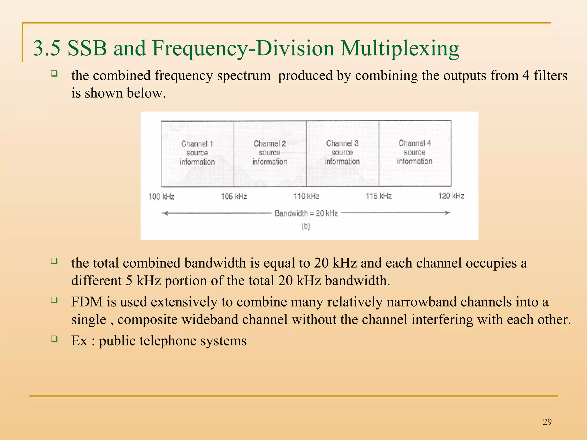
The document discusses single-sideband (SSB) communication systems. It describes three types of SSB transmission: SSB full carrier, SSB suppressed carrier, and SSB reduced carrier. It then compares SSB transmission to conventional AM, noting the bandwidth and power efficiency advantages of SSB. The document outlines two common methods for generating SSB signals: the filter method and phase-shift method. It also describes non-coherent and coherent SSB receivers. Finally, it discusses how SSB and frequency-division multiplexing are commonly used together.
Comparative Study and Performance Analysis of different Modulation Techniques...Souvik Das
Make a comparative study and performance analysis of different modulation
techniques which shows graphically and comparatively results like Bandwidth,
Energy and Power Efficiency of AM, DSB-SC, SSB and SSB-SC
Comparative Study and Performance Analysis of different Modulation Techniques...Souvik Das
Make a comparative study and performance analysis of different modulation
techniques which shows graphically and comparatively results like Bandwidth,
Energy and Power Efficiency of AM, DSB-SC, SSB and SSB-SC
This slide describe the techniques of digital modulation and Bandwidth Efficiency:
The first null bandwidth of M-ary PSK signals decrease as M increases while Rb is held constant.
Therefore, as the value of M increases, the bandwidth efficiency also increases.
This is one of a type of Analog to Digital Converter (ADC).
Through this presentation, you will have a clear view of how an ADC works. This one specifies one of the types of Analog to Digital Convertor.
The most fundamental digital modulation techniques are based on keying: PSK (phase-shift keying): a finite number of phases are used. FSK (frequency-shift keying): a finite number of frequencies are used. ... QAM (quadrature amplitude modulation): a finite number of at least two phases and at least two amplitudes are used.
the modulation of a wave by varying its amplitude, used especially as a means of broadcasting an audio signal by combining it with a radio carrier wave.
This Presentation is related to multistage amplifiers. different topics related to multistage amplifiers like two stage amplifiers. Two stage RC coupled amplifiers, cascading techniques, CE-CB cascod amplifiers, darlington pair, fet analysis
Amplitude Modulation: The type of modulation in which the amplitude of the carrier signal varies linearly with respect to the instantaneous amplitude of the message signal is called Amplitude modulation.
Types
(DSB FC, DSB SC, SSB, VSB, QAM)
Advantages and Disadvantages each type of amplitude modulation
SSBSC Single Side Band - Suppressed Carrier CompressedArijitDhali
This PowerPoint presentation is all about the definition of SSBSC or Single Side Band Suppressed Carrier. It consists of rich visuals along with the technique of modulation. Also a simplified version of derived expressions help the student to understand more about the topic. Moreover its suitable for students aiming for electronics and communication engineering.
Development of a receiver circuit for medium frequency shift keying signals.inventionjournals
Frequency shift keying (fsk) mode of digital signal information transfer switches between two predetermined frequencies of the carrier wave, either by modulating one sine wave oscillator or by switching between two oscillators.The need for a receiver to decode an fsk signal along the transmitting medium from a digital source code within about 5 kilometer radius for security monitoring of environment informed this work. The design of a receiver circuit at a frequency of 500 kHzfor an input frequency shift keying (fsk) signal from a transmitter is presented. The receiver is to receive an RF signal, amplify it, filter it to remove unwanted signals, and recover the desired base band information. It consists of an amplifier, tuned circuitsand mixers which filters the base-band information. A comparator circuit is incorporated, to detect the digital signal received. The output from the comparators is the digital equivalent of the coded signals sent by the transmitter circuit, and transferred to a microcontroller circuit, to act as a coded signal representing information from the transmitting end. The bode-plot response of the receiver to the incoming signals using a FET tuned circuit, shows that only frequencies above 470kHz, and below 495kHz are allowed to pass through the network with a resonant frequency of 483.553 kHz and a gain of 27.734dB, while others are totally attenuated. The reliability of the designed receiver circuit was evaluated for a 1 year continuous operating period and was found to be 74.7%.Area of application of this work include electronic policing of a defined environment with good success
Cracking the Workplace Discipline Code Main.pptxWorkforce Group
Cultivating and maintaining discipline within teams is a critical differentiator for successful organisations.
Forward-thinking leaders and business managers understand the impact that discipline has on organisational success. A disciplined workforce operates with clarity, focus, and a shared understanding of expectations, ultimately driving better results, optimising productivity, and facilitating seamless collaboration.
Although discipline is not a one-size-fits-all approach, it can help create a work environment that encourages personal growth and accountability rather than solely relying on punitive measures.
In this deck, you will learn the significance of workplace discipline for organisational success. You’ll also learn
• Four (4) workplace discipline methods you should consider
• The best and most practical approach to implementing workplace discipline.
• Three (3) key tips to maintain a disciplined workplace.
Taurus Zodiac Sign_ Personality Traits and Sign Dates.pptxmy Pandit
Explore the world of the Taurus zodiac sign. Learn about their stability, determination, and appreciation for beauty. Discover how Taureans' grounded nature and hardworking mindset define their unique personality.
Accpac to QuickBooks Conversion Navigating the Transition with Online Account...PaulBryant58
This article provides a comprehensive guide on how to
effectively manage the convert Accpac to QuickBooks , with a particular focus on utilizing online accounting services to streamline the process.
Remote sensing and monitoring are changing the mining industry for the better. These are providing innovative solutions to long-standing challenges. Those related to exploration, extraction, and overall environmental management by mining technology companies Odisha. These technologies make use of satellite imaging, aerial photography and sensors to collect data that might be inaccessible or from hazardous locations. With the use of this technology, mining operations are becoming increasingly efficient. Let us gain more insight into the key aspects associated with remote sensing and monitoring when it comes to mining.
Enterprise Excellence is Inclusive Excellence.pdfKaiNexus
Enterprise excellence and inclusive excellence are closely linked, and real-world challenges have shown that both are essential to the success of any organization. To achieve enterprise excellence, organizations must focus on improving their operations and processes while creating an inclusive environment that engages everyone. In this interactive session, the facilitator will highlight commonly established business practices and how they limit our ability to engage everyone every day. More importantly, though, participants will likely gain increased awareness of what we can do differently to maximize enterprise excellence through deliberate inclusion.
What is Enterprise Excellence?
Enterprise Excellence is a holistic approach that's aimed at achieving world-class performance across all aspects of the organization.
What might I learn?
A way to engage all in creating Inclusive Excellence. Lessons from the US military and their parallels to the story of Harry Potter. How belt systems and CI teams can destroy inclusive practices. How leadership language invites people to the party. There are three things leaders can do to engage everyone every day: maximizing psychological safety to create environments where folks learn, contribute, and challenge the status quo.
Who might benefit? Anyone and everyone leading folks from the shop floor to top floor.
Dr. William Harvey is a seasoned Operations Leader with extensive experience in chemical processing, manufacturing, and operations management. At Michelman, he currently oversees multiple sites, leading teams in strategic planning and coaching/practicing continuous improvement. William is set to start his eighth year of teaching at the University of Cincinnati where he teaches marketing, finance, and management. William holds various certifications in change management, quality, leadership, operational excellence, team building, and DiSC, among others.
What are the main advantages of using HR recruiter services.pdfHumanResourceDimensi1
HR recruiter services offer top talents to companies according to their specific needs. They handle all recruitment tasks from job posting to onboarding and help companies concentrate on their business growth. With their expertise and years of experience, they streamline the hiring process and save time and resources for the company.
Unveiling the Secrets How Does Generative AI Work.pdfSam H
At its core, generative artificial intelligence relies on the concept of generative models, which serve as engines that churn out entirely new data resembling their training data. It is like a sculptor who has studied so many forms found in nature and then uses this knowledge to create sculptures from his imagination that have never been seen before anywhere else. If taken to cyberspace, gans work almost the same way.
The world of search engine optimization (SEO) is buzzing with discussions after Google confirmed that around 2,500 leaked internal documents related to its Search feature are indeed authentic. The revelation has sparked significant concerns within the SEO community. The leaked documents were initially reported by SEO experts Rand Fishkin and Mike King, igniting widespread analysis and discourse. For More Info:- https://news.arihantwebtech.com/search-disrupted-googles-leaked-documents-rock-the-seo-world/
Business Valuation Principles for EntrepreneursBen Wann
This insightful presentation is designed to equip entrepreneurs with the essential knowledge and tools needed to accurately value their businesses. Understanding business valuation is crucial for making informed decisions, whether you're seeking investment, planning to sell, or simply want to gauge your company's worth.
Explore our most comprehensive guide on lookback analysis at SafePaaS, covering access governance and how it can transform modern ERP audits. Browse now!
RMD24 | Retail media: hoe zet je dit in als je geen AH of Unilever bent? Heid...BBPMedia1
Grote partijen zijn al een tijdje onderweg met retail media. Ondertussen worden in dit domein ook de kansen zichtbaar voor andere spelers in de markt. Maar met die kansen ontstaan ook vragen: Zelf retail media worden of erop adverteren? In welke fase van de funnel past het en hoe integreer je het in een mediaplan? Wat is nu precies het verschil met marketplaces en Programmatic ads? In dit half uur beslechten we de dilemma's en krijg je antwoorden op wanneer het voor jou tijd is om de volgende stap te zetten.
Personal Brand Statement:
As an Army veteran dedicated to lifelong learning, I bring a disciplined, strategic mindset to my pursuits. I am constantly expanding my knowledge to innovate and lead effectively. My journey is driven by a commitment to excellence, and to make a meaningful impact in the world.
1. 1
Chapter 3 : Single-Sideband (SSB) Communication System
Chapter contents
3.1 Single-Sideband System
SSBFC, SSBSC, SSBRC
3.2 Transmission to Conventional AM
3.3 Single-Sideband Transmitters
Filter method, Phase-Shift Method
3.4 Single-Sideband Receivers
SSB BFO Receiver, Coherent SSB BFO Receiver
3.5 Single-Sideband and Frequency-Division Multiplexing
2. 2
Chapter 3 : Single-Sideband (SSB) Communication System
2 main disadvantages of the conventional AM DSBFC
Carrier power constitutes 2/3 or more of the total transmitted power – no
information in the carrier.
Utilize twice as much bandwidth – both the upper and lower sideband actually
contains same information (redundant).
3. 3
3.1.1 : AM Single-Sideband Full Carrier (SSBFC)
The carrier is transmitted at full power but only one sideband is transmitted
requires half the bandwidth of DSBFC AM
SSBFC requires less total power but utilizes a smaller percentage of the power to
carry the information
4. 4
3.1.1 : AM Single-Sideband Full Carrier (SSBFC)
The output modulated signal
as SSB only has one sideband, the peak change in the envelope is only half of
what it is with DSBFC
Therefore, the demodulated wave has only half the amplitude of the DSB
modulated wave
5. 5
3.1.2 : AM Single-Sideband Suppressed Carrier (SSBSC)
The carrier is totally suppressed and one sideband is removed
requires half the bandwidth of DSBFC AM
Sideband power makes up 100% of the total transmitted power
The wave is not an envelope but a sine wave at frequency equal to the carrier
frequency ±modulating frequency (depending on which sideband is transmitted)
6. 6
3.1.3 : AM Single-Sideband Reduced Carrier (SSBRC)
One sideband is totally removed and the carrier voltage is reduced to
approximately 10% of its unmodulated amplitude
requires half the bandwidth of DSBFC AM
Less transmitted power than DSBFC and SSBFC but more power than SSBSC
As much as 96% of the total transmitted power is in the sideband
The output modulated signal is similar to SSBFC but with reduced maximum and
minimum envelope amplitudes
7. 7
3.2 : Comparison of Single-Sideband Transmission to
Conventional AM
With SSB, only one sideband is transmitted and the carrier is either
suppressed or reduced significantly
Eliminating the carrier would increase the power available for the sidebands
by at least a factor of 3, providing approximately a 4.8 dB improvement in the
signal-to-noise ratio
3.2.1 SSB Advantages : Power Conservation
8. 8
50% reduction in bandwidth for a SSB compared to DSB equal to an
improvement in the signal-to-noise ratio of 3 dB
By combining the bandwidth improvement and the power advantage of
removing the carrier, the overall improvement in the signal-to-noise ratio
using SSBSC is approximately 7.8 dB better that DSBFC
3.2.2 SSB Advantages : Bandwidth Conservation
9. 9
With DSB, the carrier and two sidebands may propagate through the channel
by different paths and experience different transmission impairment called as
selective fading.
3 types of selective fading :
Sideband fading : one sideband is significantly attenuated resulting in a reduced
signal amplitude at the output of the receiver and causing some distortion but not
detrimental to the signal because the 2 sidebands contain the same information.
Carrier fading : reduction of the carrier level of a 100% modulated wave will
make the carrier voltage less than the sum voltage of the sidebands.
Carrier or sideband phase shift : as the position change, a change in the shape of
the envelope will occur, causing severely distorted demodulated signal.
3.2.3 SSB Advantages : Selective Fading
10. 10
As SSB only utilizes half as much bandwidth as conventional AM, the
thermal noise power is reduced to half that of a DSB system
Considering both the bandwidth reduction and the immunity to the selective
fading, SSB system has an approximately a 12 dB S/N ratio advantage over
DSB system
3.2.4 SSB Advantages : Noise Reduction
11. 11
SSB requires more complex and expensive receivers than DSB.
As SSB includes either a reduced or a suppressed carrier, envelope detection
cannot be used. SSB requires a carrier recovery and synchronization circuit,
which adds to their cost, complexity and size.
3.2.5 SSB Disadvantages : Complex receivers
3.2.6 SSB Disadvantages : Tuning difficulties
SSB receivers require more complex and precise tuning than the DSB
receivers.
12. 12
3.3 : SSB Transmission
transmitters used for SSB suppressed and reduced carrier transmission are
identical except that the re-inserted carrier transmitters have an additional
circuits that adds a low amplitude carrier to the single sideband waveform
after suppressed-carrier modulation has been performed and one of the
sideband has been removed.
the re-inserted carrier is called a pilot carrier.
the circuit where the pilot carrier is re-inserted is called a linear summer.
3 transmitter configurations are commonly used for single sideband
generation :
Filter method
Phase shift method
Third method
13. 13
3.3.1 : Filter Method
Block diagram for a SSB transmitter using balanced modulators to suppressed
the unwanted carrier and filters to suppress the unwanted sideband.
The low frequency IF is converted to the final operating frequency band through
a series of frequency translation
3-stages of frequency up-conversion
modulating signal is an audio spectrum that extends from 0 kHz ~ 5 kHz
14. 14
3.3.1 : Filter Method
modulating signal mixes with a low frequency (LF) 100 kHz carrier in the balanced
modulator 1 to produced a DSB frequency spectrum centered at the suppressed 100
kHz carrier.
bandpass filter 1 (BPF 1) that is tuned to a 5 kHz bandwidth centered at 102.5 kHz
used to eliminate the lower sideband and pass only the upper sideband.
the pilot carrier or reduced amplitude carrier is added to the single-sided waveform in
the carrier re-insertion stage (summer).
the summer is a simple adder circuit that combines the 100 kHz pilot carrier with the
100 kHz ~ 105 kHz upper sideband frequency spectrum.
15. 15
3.3.1 : Filter Method
Output of the summer is the SSBRC waveform. the SSBRC waveform is mixed in the
balanced modulator 2 with a 2 MHz medium frequency (MF) carrier.
output is a DSB suppressed carrier signal in which the upper and lower sidebands
each contain the original SSBRC frequency spectrum.
upper and lower sidebands are separated by a 200 kHz frequency band that is void of
information.
16. 16
3.3.1 : Filter Method
the lower sideband then is filtered (cut) through the BPF 2 (5 kHz bandwidth centered
at 2.1025 MHz.
the output from BPF 2 is once again a single sideband reduced carrier waveform with
a reduced 2.1 MHz carrier and a 5 kHz wide upper sideband.
then the SSBRC waveform from BPF 2 is mixed in the balanced modulator 3 with the
20 MHz high frequency carrier (HF), producing a double sideband suppressed carrier
signal in which the upper and lower sidebands each contain the original SSBRC
frequency spectrum.
upper and lower sidebands are separated by a 4.2 MHz frequency band that is void of
information.
17. 17
3.3.1 : Filter Method
the lower sideband then is filtered (cut) through the BPF 3 (5 kHz bandwidth
centered at 22.1025 MHz.
the output from BPF 3 is once again a single sideband reduced carrier waveform with
a reduced 22.1 MHz RF carrier and a 5 kHz wide upper sideband.
Conclusion
the original modulating signal frequency spectrum was up-converted in 3 modulation
steps to a final carrier frequency of 22.1 MHz and a single upper sideband that
extended from the carrier (22.1 MHz) to 22.105 MHz.
after each up-conversion (frequency translation), the desired sideband is separated
from the double sideband spectrum with a bandpass filter (BPF).
18. 18
3.3.1 : Filter Method
Why not using single heterodyning process (1 balanced modulator, 1 bandpass
filter & single HF carrier) ?
Block diagram of a single conversion SSBSC transmitter :
the output of the balance modulator is a DSB spectrum centered around a suppressed
carrier frequency of 22.1 MHz.
19. 19
3.3.1 : Filter Method
to separate the 5 kHz upper sideband from the composite spectrum, a bandpass filter
with extremely high Q is required.
for fixed modulating bandwidth, the filter Q increase rapidly with the centre
frequency.
the difficulty with this method : the filter with high Q is difficult to construct and not
economic.
B
f
Q
c
=
20. 20
3.3.2 : Phase Shift Method
with phase-shift method, the undesired sideband is cancelled in the output of the
modulator.
Block diagram of a SSB transmitter using phase-shift method :
use 2 separate DSB modulators (balanced modulator 1 & 2).
modulating signal and carrier are applied directly to one of the modulators, then both
are shifted 90º and applied to the second modulator.
the outputs from the two balanced modulators are DSBSC signals with the proper
phase (when they are combined in a linear summer, the upper sideband is cancelled).
21. 21
3.3.2 : Phase Shift Method
Mathematical analysis of the phase-shift transmitter :
modulating signal (sin wmt) is fed directly to balanced modulator 1 and shifted 90º (cos
wmt) and fed to balanced modulator 2.
carrier signal (sin wmt) is also fed directly to balanced modulator 1 and shifted 90º (cos
wmt) and fed to balanced modulator 2
the outputs of the balanced modulators are expressed as
Output of balanced modulator 1 :
(1)
Output of balanced modulator 2 :
(2)
( )tt
tt
mcmc
cm
ωωωω
ωω
+−−=
=
cos
2
1
)cos(
2
1
))(sin(sin
( )tt
tt
mcmc
cm
ωωωω
ωω
+−−=
=
cos
2
1
)cos(
2
1
))(cos(cos
22. 22
3.3.2 : Phase Shift Method
the final output from the linear summer :
(3)
which is the lower sideband of the AM wave.
( ) ( ) ( ) ( )tttt mcmcmcmc ωωωωωωωω ++−++−− cos
2
1
cos
2
1
cos
2
1
cos
2
1
( )tmc ωω −= cos
23. 23
3.4 SSB Receivers
3.4.1 : SSB BFO Receiver
Block diagram for a simple noncoherent SSB BFO receiver :
in a receiver, the input signal (suppressed or reduced carrier and one sideband) is
amplified and then mixed with the RF local oscillator frequency to produce
intermediate frequency.
the output from the RF mixer is then goes through further amplification and band
reduction prior to second mixer.
the output from the IF amplifier stage is then mixed (heterodyned) with beat
frequency oscillator (BFO) frequency.
24. 24
3.4.1 : SSB BFO Receiver
BFO frequency is equal to the IF carrier frequency. Thus the difference between the
IF and the BFO frequency is the information signal.
i.e. the output from the IF mixer is the sum and difference frequencies between the IF
and the beat frequency. The difference frequency band is the original input
information.
the receiver is classified as noncoherent because the RF oscillator and the BFO
signals are not synchronized to each other and to the oscillators in the transmitter.
Consequently, any difference between the transmitter and receiver local oscillator
frequencies produces a frequency offset error in the demodulated information signal.
the RF mixer and IF mixer are product detectors. A product detector and balanced
(product) modulator are essentially the same circuit.
25. 25
3.4.2 : Coherent SSB BFO Receiver
Block diagram for a coherent SSB BFO receiver :
this type of receiver is identical to the previous noncoherent type, except that the
LO and BFO frequencies are synchronized to the carrier oscillators in the
transmitter.
the carrier recovery circuit is a narrowband PLL that tracks the pilot carrier in the
SSBRC signal.
the recovered carrier is then used to generate coherent local oscillator frequencies (RF
LO frequency & BFO frequency) in the synthesizer.
26. 26
3.4.2 : Coherent SSB BFO Receiver
any minor changes in the carrier frequency in the transmitter are compensated in the
receiver, and the problem of frequency offset error is eliminated.
27. 27
3.5 SSB and Frequency-Division Multiplexing
the most common application of SSB
(especially SSBSC) is frequency-
division multiplexing (FDM) due to
the bandwidth and power efficiencies
of SSB system.
Frequency-division multiplexing is an
analog method of combining two or
more analog sources that originally
occupied the same frequency band in
such a manner that the channels do
not interfere with each other
Example of simple FDM system
where four 5 kHz channels are
frequency-division multiplexed into a
single 20 kHz channel :
28. 28
3.5 SSB and Frequency-Division Multiplexing
channel 1 signals modulate a 100 kHz
carrier in a balanced modulator. The output
is a DSBSC with a bandwidth of 10 kHz.
the DSBSC wave is then passed through
BPF producing a SSBSC signal occupying
the frequency band between 100 kHz and
105 kHz.
channel 2 signals modulate a 105 kHz
carrier producing a DSBSC wave that is
converted to SSBSC by passing it through
a BPF.
the output from the BPF occupies the
frequency band between 105 kHz and 110
kHz.
similar process is used to convert channel 3
and channel 4 signals to the frequency
bands 110 kHz to 115 kHz and 11f kHz to
120 kHz, respectively.
29. 29
3.5 SSB and Frequency-Division Multiplexing
the combined frequency spectrum produced by combining the outputs from 4 filters
is shown below.
the total combined bandwidth is equal to 20 kHz and each channel occupies a
different 5 kHz portion of the total 20 kHz bandwidth.
FDM is used extensively to combine many relatively narrowband channels into a
single , composite wideband channel without the channel interfering with each other.
Ex : public telephone systems