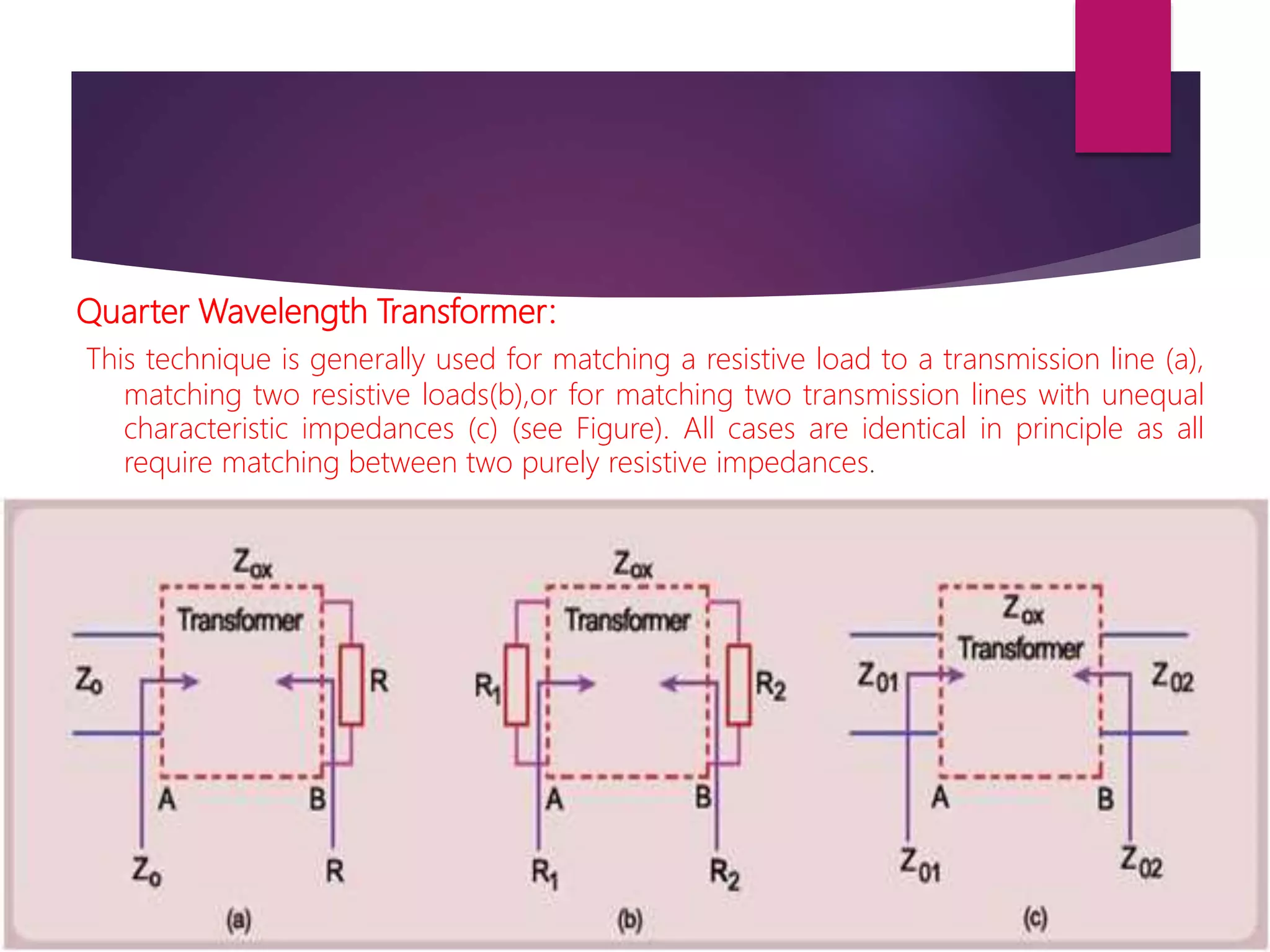
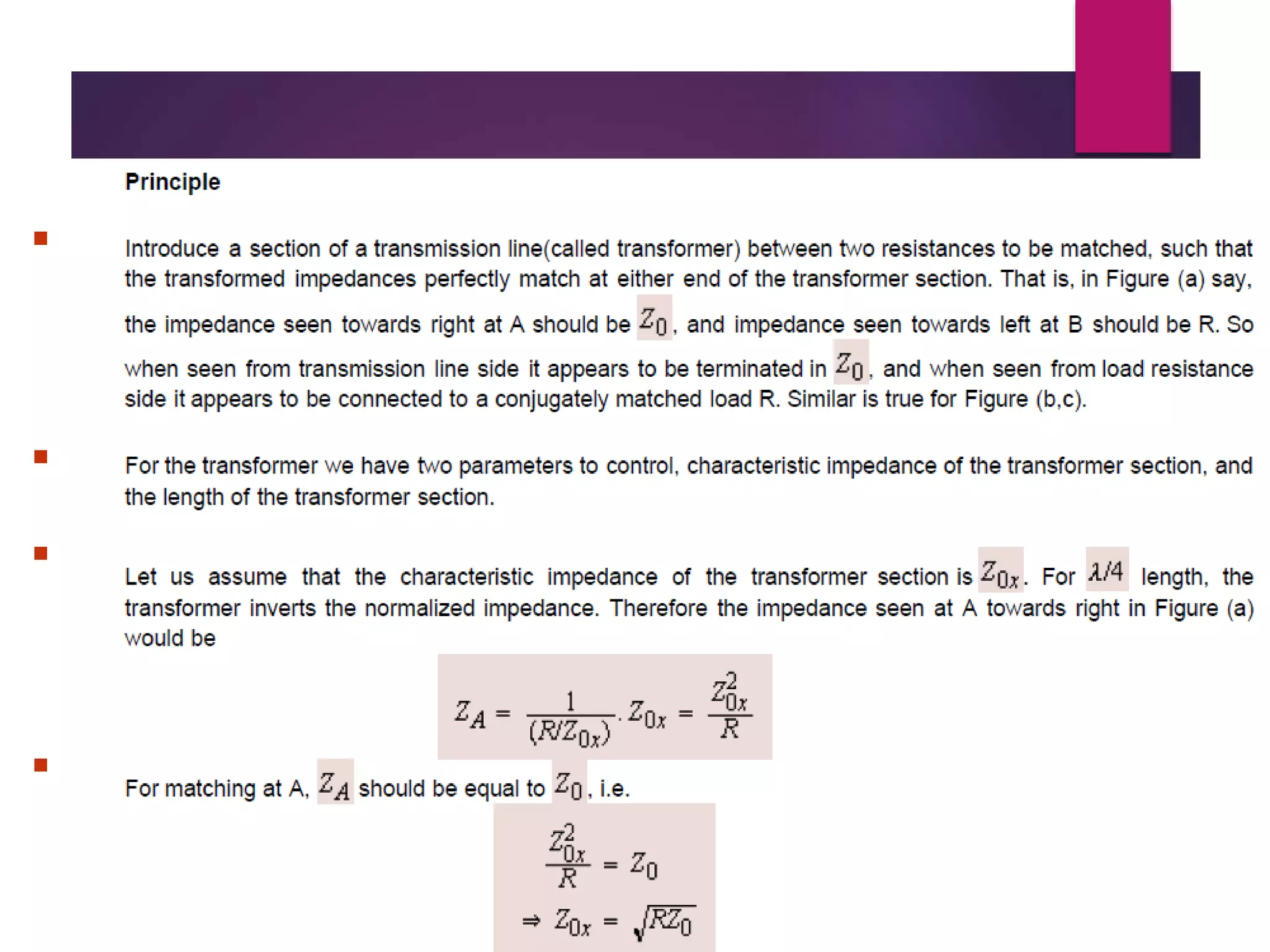
In electronics, impedance matching is the practice of designing the input impedance of an electrical load or the output impedance of its corresponding signal source to maximize the power transfer or minimize signal reflection from the load.
result management system report for college project
Impedance Matching
1. Impedance Matching
Impedance matching is one of the important aspects of
high frequency circuit analysis. To avoid reflections and
for maximum power transfer the circuits have to be
impedance matched.
Transmission line sections can be used for the purpose
of impedance matching.
There are various impedance matching techniques
which are discussed in the following :
2. Quarter Wavelength Transformer:
This technique is generally used for matching a resistive load to a transmission line (a),
matching two resistive loads(b),or for matching two transmission lines with unequal
characteristic impedances (c) (see Figure). All cases are identical in principle as all
require matching between two purely resistive impedances.
3.
4. CONCLUSION:
Two resistive impedances can be matched by a section of a transmission line
which is quarter-wavelength long and has characteristic impedance equal to the
geometric mean of the two resistances.
The quarter wavelength transfer is commonly used at the junction of two
transmission lines of unequal characteristic impedances.
Drawback:
This technique needs special line of characteristics impedance for every pair of
resistances to be matched.