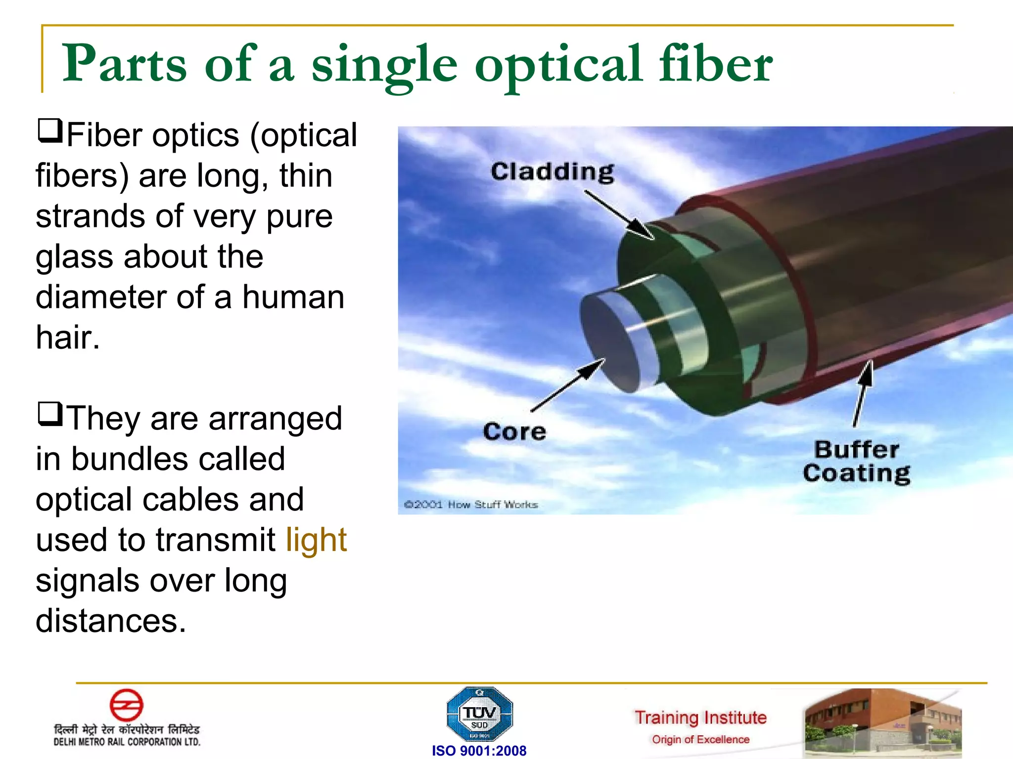
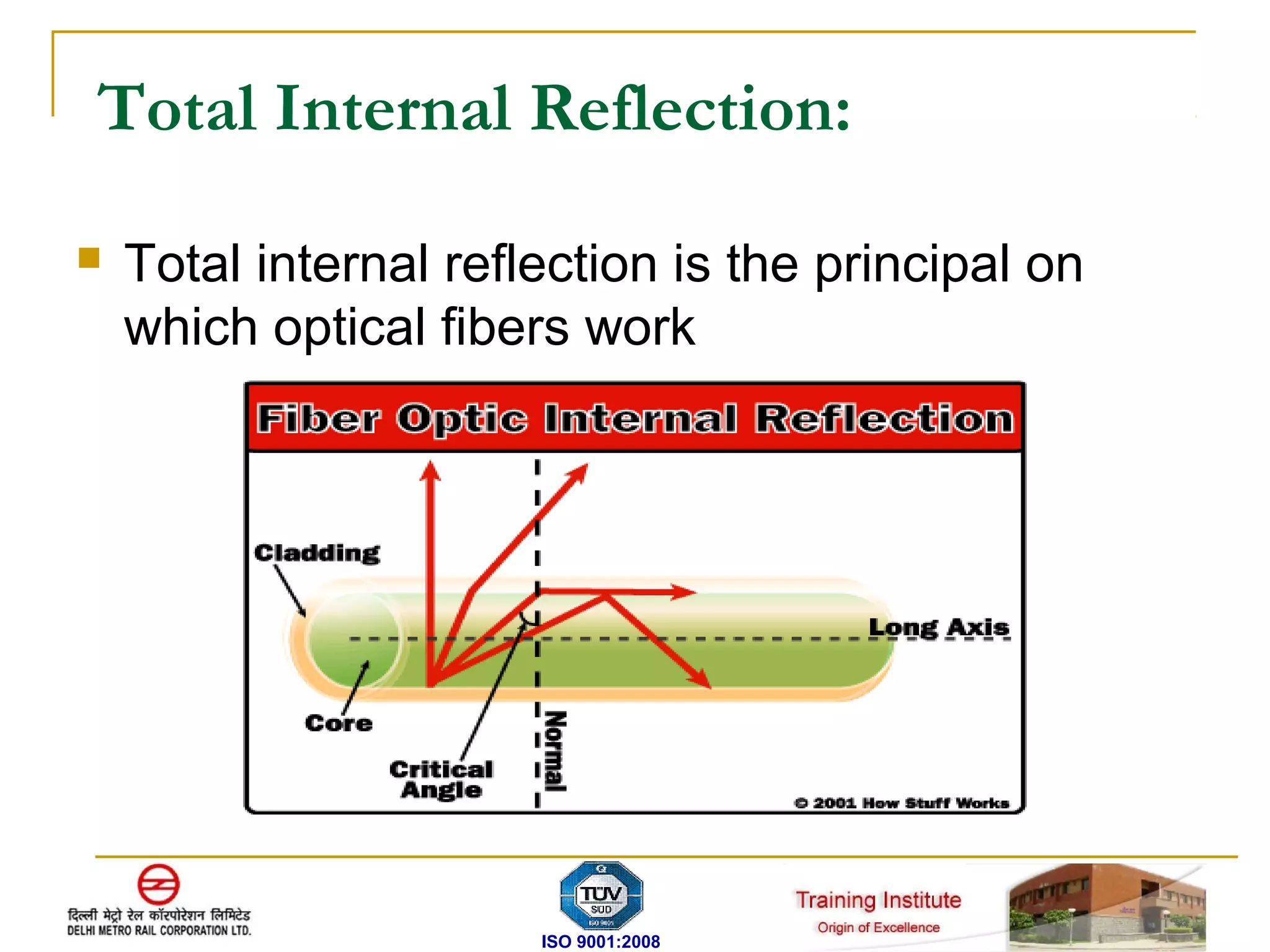
The document discusses fiber optic transmission systems (FOTS). It describes how FOTS uses optical fibers to transmit information over long distances using light signals. It discusses the key components of a FOTS including transmitters, optical fibers, optical receivers, and how total internal reflection allows fibers to transmit signals. The document also covers fiber types, advantages of FOTS over copper wire, components in DMRC's network, and technologies like SDH used for optical communication.
TELECOMMUNICATION DEPARTMANT
It is the department of DMRC, which deals with the protection, supervision and operation of the train. In short it the department that manages the metro traffic on the rails. Transmission of information is possible through co-axial cables, wireless media, fibre optics. Communication at a distance by electronics transmission of impulses, as by telegraph, cable, telephone, radio, or television constitutes telecommunication.
The period of 6 weeks of training in Delhi Metro Rail Corporation was a learning experience. It presented an opportunity of seeing how engineers work and co-ordinate in an organization. The study of various Hierarchies in a Delhi Metro Rail enriched the knowledge regarding the various levels of government organization.
The review of the Signal & Telecommunication where the collection of Communication through respective Stations and track of Delhi Metro were compiled and summarised to prepare the Signal & Telecommunication and to know the process of working in an organization in co-ordination.
It also helped to gain an opportunity to study the various community/stakeholders participations of various Signal & Communication units. This enhanced the report writing skills and presentation techniques for the future.
It raised up the knowledge regarding Signal & Telecommunication and also the participation of Communication company’s of different associations like BEL, BHEL, HCL etc are involved in Electronics and Communication field.
Thus, the Signal & Telecommunication Department helped us to review the various techniques and inventions which are required to be implemented properly to make the vision of Electronics world of future successful.
Optical fiber Communication training reporthuzaifa027
This is the complete report of my summer training done in optical fiber installation and technician. You will find all the stuff related to optical fiber installation.
INTRODUCTION LiFi , also known as "Light Fidelity" is a wireless optical networking technology, which uses lightemitting diodes (LEDs) to transmit data. In 2011, professor Haas made a LiFi Harald demonstration at the TED (Technology, Entertainment, Design) Global Talk on Visible Light Communication (VLC).
LiFi (also known as light fidelity) is a technology for the wireless transmission of data between devices LiFi uses light as a medium for transmission of data. LED are the source used for encoding data by switching the light on and off during regular intervals to create a binary code.
An Economics of Nano technology: The relative importance of Governmental fund...IJERA Editor
The non technology applications are taking the business applications are increasing. Private activities coupled with governmental funding bestows competitive advantage on nations. Unless India gears up fast and quick it would lose yet one more business race especially in the context of liberation, globalization and privatization reforms that it has entered.The nanotechnology patent applications published in different countries’/regions’ patent offices have been evaluated by using the esp@cenet ‘‘worldwide’’ database. A longitudinal analysis is done on nanotechnology patent applications data from 1991-2008. Indian data and contributions are revealed as sparse. Semiconductor devices; electric solid state devices not otherwise provided for’’ (H01L) ranked first, followed by ‘‘Preparations for medical, dental, or toilet purposes’’ (A61K).
International Journal of Engineering Research and Applications (IJERA) is an open access online peer reviewed international journal that publishes research and review articles in the fields of Computer Science, Neural Networks, Electrical Engineering, Software Engineering, Information Technology, Mechanical Engineering, Chemical Engineering, Plastic Engineering, Food Technology, Textile Engineering, Nano Technology & science, Power Electronics, Electronics & Communication Engineering, Computational mathematics, Image processing, Civil Engineering, Structural Engineering, Environmental Engineering, VLSI Testing & Low Power VLSI Design etc.
Fiber type and corresponding optical transceiversAngelina Li
Fiber optic patch cable as the basic element of a network, transmits signals through strands of glass or plastic fiber. Fiber optic cables are available in multimode and single-mode fibers terminated with LC, SC, ST, LC, FC, MTRJ, E2000 connectors in simplex and duplex. The typical multimode fiber used in telecom or datacom applications has a core size of 50 or 62.5 microns. Single-mode fiber shrinks the core size down to 9 microns so that the light can only travel in one ray.
this topic covered guided media including twisted pair cable, coaxial cable and fiber optic cable and their working process advantages and applications.
Fiber optics communication & TechnologyPrateek Kumar
Higher Education The growing importance of high-tech, interactive instruction – both in the classroom and online – places an ever-increasing load on your network. We help you assess your current and future demands and design a solution that satisfies tech-savvy students’ demands while delivering the effective content your instructional goals require. As technologies evolve and you’re ready to grow, we’ll be there, ready to grow with you.
K-12 Education With apps aimed at toddlers and pre-schoolers carrying personal tablets, you have no choice but to deliver current connectivity – both to meet expectations of tech-savvy kids and to ensure that less-privileged students have the opportunity to keep up with their peers. Our custom solutions address your current and future needs, as well as your budget restrictions. Get the exact connectivity you need now and we’ll be ready to help you expand when and if you need to.
Garth naar - optical fibre communication telecommunicationsgarthnaar
Fibre optic communication has revolutionised the telecommunications industry. It has also made its presence widely felt within the data networking community as well. Using fibre optic cable, optical communications have enabled telecommunications links to be made over much greater distances and with much lower levels of loss in the transmission medium and possibly most important of all, fiber optical communications has enabled much higher data rates to be accommodated.
CW RADAR, FMCW RADAR, FMCW ALTIMETER, AND THEIR PARAMETERSveerababupersonal22
It consists of cw radar and fmcw radar ,range measurement,if amplifier and fmcw altimeterThe CW radar operates using continuous wave transmission, while the FMCW radar employs frequency-modulated continuous wave technology. Range measurement is a crucial aspect of radar systems, providing information about the distance to a target. The IF amplifier plays a key role in signal processing, amplifying intermediate frequency signals for further analysis. The FMCW altimeter utilizes frequency-modulated continuous wave technology to accurately measure altitude above a reference point.
Saudi Arabia stands as a titan in the global energy landscape, renowned for its abundant oil and gas resources. It's the largest exporter of petroleum and holds some of the world's most significant reserves. Let's delve into the top 10 oil and gas projects shaping Saudi Arabia's energy future in 2024.
Sachpazis:Terzaghi Bearing Capacity Estimation in simple terms with Calculati...Dr.Costas Sachpazis
Terzaghi's soil bearing capacity theory, developed by Karl Terzaghi, is a fundamental principle in geotechnical engineering used to determine the bearing capacity of shallow foundations. This theory provides a method to calculate the ultimate bearing capacity of soil, which is the maximum load per unit area that the soil can support without undergoing shear failure. The Calculation HTML Code included.
Overview of the fundamental roles in Hydropower generation and the components involved in wider Electrical Engineering.
This paper presents the design and construction of hydroelectric dams from the hydrologist’s survey of the valley before construction, all aspects and involved disciplines, fluid dynamics, structural engineering, generation and mains frequency regulation to the very transmission of power through the network in the United Kingdom.
Author: Robbie Edward Sayers
Collaborators and co editors: Charlie Sims and Connor Healey.
(C) 2024 Robbie E. Sayers
Hierarchical Digital Twin of a Naval Power SystemKerry Sado
A hierarchical digital twin of a Naval DC power system has been developed and experimentally verified. Similar to other state-of-the-art digital twins, this technology creates a digital replica of the physical system executed in real-time or faster, which can modify hardware controls. However, its advantage stems from distributing computational efforts by utilizing a hierarchical structure composed of lower-level digital twin blocks and a higher-level system digital twin. Each digital twin block is associated with a physical subsystem of the hardware and communicates with a singular system digital twin, which creates a system-level response. By extracting information from each level of the hierarchy, power system controls of the hardware were reconfigured autonomously. This hierarchical digital twin development offers several advantages over other digital twins, particularly in the field of naval power systems. The hierarchical structure allows for greater computational efficiency and scalability while the ability to autonomously reconfigure hardware controls offers increased flexibility and responsiveness. The hierarchical decomposition and models utilized were well aligned with the physical twin, as indicated by the maximum deviations between the developed digital twin hierarchy and the hardware.
1. Delhi Metro Rail Corporation
Training Institute
ISO 9001:2008
ISO 9001:2008
FIBER OPTIC TRANSMISSON SYSTEM
2. Fiber Optics Transmission system FOTS
FOTS stands for Fiber Optics Transmission system. It is
the transmission system that uses optical fiber as
communication media. Thus optical fiber communication
is the method of transmitting information through optical
fibers.
Optical fibers can be used to transmit light and thus
information over long distances.
They are largely used for telephony, but also for Internet
traffic, long high-speed local area networks (LANs),
cable-TV, and increasingly also for shorter distances.
ISO 9001:2008
3. Parts of a single optical fiber
Fiber optics (optical
fibers) are long, thin
strands of very pure
glass about the
diameter of a human
hair.
They are arranged
in bundles called
optical cables and
used to transmit light
signals over long
distances.
ISO 9001:2008
4. Optical fiber types
Single mode fibers
Single-mode fibers have small cores and transmit
infrared laser light. Some optical fibers can be made
from plastic. These fibers have a large core and transmit
visible red light from LEDs.
Multimode fibers
Multi-mode fibers have larger cores and transmit infrared
light from light-emitting diodes (LEDs).
ISO 9001:2008
5. Total Internal Reflection:
Total internal reflection is the principal on
which optical fibers work
ISO 9001:2008
6. Fiber optic relay system
Fiber optic relay system consists of the following:
Transmitter - Produces and encodes the light signals
Optical fiber - Conducts the light signals over a distance
Optical regenerator - May be necessary to boost the
light signal (for long distances)
Optical receiver - Receives and decodes the light
signals
ISO 9001:2008
7. Advantages of Fiber Optics:
Compared to conventional metal wire (copper wire), optical fibers are:
1.Less expensive
Several miles of optical cable can be made cheaper than equivalent
lengths of copper wire. This saves your provider (cable TV, Internet)
and your money.
2.Thinner
Optical fibers can be drawn to smaller diameters than copper wire.
3.Less signal degradation
The loss of signal in optical fiber is less than in copper wire.
ISO 9001:2008
4.Non-flammable
Because no electricity is passed through optical fibers, there is no
fire hazard.
8. 5.Higher carrying capacity
Because optical fibers are thinner than copper wires, more fibers
can be bundled into a given-diameter cable than copper wires. This
allows more phone lines to go over the same cable or more
channels to come through the cable into your cable TV box.
ISO 9001:2008
6.Light signals
Unlike electrical signals in copper wires, light signals from one fiber
do not interfere with those of other fibers in the same cable. This
means clearer phone conversations or TV reception.
7.Low power Transmitters
Because signals in optical fibers degrade less, lower-power
transmitters can be used instead of the high-voltage electrical
transmitters needed for copper wires. Again, this saves your
provider and you money.
9. ISO 9001:2008
8.Digital signals
Optical fibers are ideally suited for carrying digital information,
which is especially useful in computer networks.
9.Lightweight
An optical cable weighs less than a comparable copper wire cable.
Fiber-optic cables take up less space in the ground.
10.Flexible
Because fiber optics are so flexible and can transmit and receive
light, they are used in many flexible digital cameras for the
following purposes:
Medical imaging - in bronchoscopes, endoscopes, laparoscopes
Mechanical imaging - inspecting mechanical welds in pipes and
engines (in airplanes, rockets, space shuttles, cars)
Plumbing - to inspect sewer lines
10. Losses in Optical Fiber Cable
ISO 9001:2008
Attenuation loss
Attenuation loss takes place due to coupler, splices, connectors,
fiber itself. Attenuation varies with the wavelength of the light
850 nm- 2.5 to 3.0 dB/km
1310 nm- 0.4 to 0.5 dB/km
1550 nm- 0.25 to 0.3 dB/km
Absorption
Absorption is a natural property of glass itself. Losses due to
absorption are very large in UV and infra red regions.
11. ISO 9001:2008
Scattering
Loss of the optical energy is due to imperfections in the fiber. Light
is scattered in all directions, which causes the loss of power in
forward direction, known as Rayleigh scattering loss, takes place
due to variations in the density and composition of glass material in
the fiber. Rayleigh scattering loss is inversely proportional to four
power of wavelength, i.e., for high wavelength, losses will be small.
Macro and Micro bending
i) Macro bending: Loss is caused due to deformation of fiber axis
during cabling process.
ii) Micro bending: Excessive bending of the cable or fiber may
result in loss known as micro bend loss. For single mode fiber
attenuation at longer wavelength like 1550 nm is sensitive to
bending.
12. Fiber Optics Transmission System (FOTS) in DMRC
FOTS can be termed as the backbone of DMRC
telecommunication network.
Fiber optics eases up the data and voice communication
or access to various systems at different stations.
This network is based on fiber optical cables on both
sides of the track.
The number of fibers is determined in order to comply
with redundancy. The fiber is redundant for security and
protection.
In case of fiber optic failure, communication can take
place via spare fiber while the fiber that is down may be
fixed.
ISO 9001:2008
13. The main components of the fiber optic transmission
system are:
1. Optical fiber cables
2. Synchronous Digital Hierarchy (SDH)
3. Digital Distribution Frame (DDF)
4. Flexible Multiplexer (FMX)
5. Optical Distribution Frame (ODF)
1. Optical fiber cables are used for the transmission of
the data from one station to the other station. Mainly the
clock signal from the master clock is transmitted as it
helps in the synchronization so that it does not cause
any delay in the data transmission and hence the metro
trains can run in their required time.
ISO 9001:2008
14. SDH:
SDH i.e synchronous digital hierarchy is the technique used for the
optical communication. Before knowing in depth about the SDH we
should know about the PDH, which was used before the advent of
SDH.
PDH (Pleisochronous Digital Hierarchy):
PDH uses copper wire to transmit information from one
station to other hence, increased I2R losses, eddy current losses,
current and voltage range limitations and need of repeaters after
very small distance, all these factors discouraged the use of PDH.
One major drawback is multiplexing and demultiplexing at all
stations through which information passes. Troubleshooting is
rigorous task due to increased complexity. Due to above mentioned
factors, we have switchover from PDH to SDH technology.
ISO 9001:2008
15. Pliesochronous means ‘just synchronous’. In PDH technique
different clocks were used and all the clocks cannot be same at
same time or synchronous. Also in PDH system, while sending E1
channel, 64kbps additional bits are sent called the stuffing bits and
the pointer associated tells whether bits in 64kbps are data or just
stuff. If bits are stuff then they are not demultiplexed at the
destination.
Limitations of PDH:
Not manageable from central network
Not completely synchronized
Not standardized
Less Bandwidth (due to physical media)
Thus to overcome the above limitations we use SDH technique.
ISO 9001:2008
16. SDH(Synchronous Digital Hierarchy):
In SDH, information is transferred through optical fiber. Through
this technology we are able to transmit data in terabytes using
wavelength 1310 nm.
There is no need to demultiplex whole information coming from
side by stations. Information to side by stations is passed using
STM-4 (Synchronized Transport Module) at 622.08 Mbps.
4 STM1 multiplexed in TDM (Time Division Multiplexing) forms
STM-4. In this technology repeaters are required at comparatively
larger distances.
ISO 9001:2008
E2=4 E1
E3=4 E2=16 E1
E4=4 E3=16 E2= 64E1
STM1=63 E1
17. Formation of E1 channel
E1 is the tributary signal for SDH to work.
0 1 2 3 4 5 ……………… 16 ………………… 31
ISO 9001:2008
1::
7
256 such data packets give 65536 bps, approx. 64 kbps. 32 time slots
of 64 kbps give E1 signal transmitting @ 2.048Mbps. E1 is bi-directional
signal Out of these 32 channels 30 are used as voice channel while 2
are used for control and signaling information.
0 16 31
0 – Control data
16 - Signaling data: Carries information about the path E1 goes through.
18. DDF (Digital Distribution Frame).
The DDF basically provides a flexible way of
connecting equipment side to cable side. From
the DDF the system working at 2 Mbps rate is
directly provided the connections with required
number of E1 lines.
ISO 9001:2008
19. ISO 9001:2008
FMX/Access MUX:
If data rate is less than 64 Mbps then, it is termed as
sub-rate. If data rate is more than 64 Mbps then it is
termed as super rate.
Access-MUX is used for systems requiring transfer
rate below 2.048 Mbps. It multiplex the data from the
systems operating at the data rates lower than 2 Mbps
into E1 lines.
Since no single node will be able to use all the
bandwidth therefore, all the data i.e. audio and video
signals are multiplexed in order to make maximum use
of available bandwidth.
FMX is interfaced with Clock system, Cameras, Radio,
NP-SCADA, etc.
20. Optical Distribution Frame (ODF):
GSS and FPS together forms ODF (Optical Distribution Frame). At
each node (or station), optical fiber cables are terminated in the
GSS (Generic Splicing Self) and are distributed to the system
through FPS (Fiber Patching Shelf).
From the FPS patch cords, both ends have connectors for
connection, are sent to the SDH where apart from being converted
to electrical signal, the signals required at the particular node
dropped (or extracted) and multiplexed into E1 lines at 2.048 Mbps
which are terminated at DDF (Digital Distribution Frame).
The DDF basically provides a flexible way of connecting equipment
side to cable side. From the DDF the system working at 2 Mbps rate
is directly provided the connections with required number of E1
lines. The systems working with lower rates than 2 Mbps access the
network through FMX.
The FMX demultiplexes the E1 lines coming from DDF to the lines
at the lower rates for use of various systems.
ISO 9001:2008
21. There are two GSS, one for up (in Depot direction) and other for
down (opposite to Depot). There are 48 trays in each GSS. All fibers
coming from and going to adjacent stations are passing through
GSS. Fibers needed at particular station are connected to FPS in
zero dB connector (0.3dB loss) through pigtail cords, connector at
one end only. These fibers are then passed to SDH. And fibers not
needed at particular station are spliced through.
Splicing is a technique for joining together individual fiber or optical
cable sections to forms continuous lines for these long distant links.
Splicing can be done in two ways:
Mechanical Splices: This aligns the axis of the two fibers to be joint
and physically hold them together.
Fusion Splices: This is accomplished by applying localized heating
(i.e. by electric arc or flame) at the interface between two butted,
pre-aligned fiber ends, causing them to soften and fuse together.
In DMRC fusion splicing is used. Splicing loss is around 0.1dB
ISO 9001:2008
22. In DMRC only 2 fibers for each side are used for transmission in
both directions. 24 fibers optical cable is used at elevated stations,
36 fibers optical cable at underground stations and 48 fibers cable
at OCC. These figures are selected on the basis of need of
information to be received or passed.
Equipments used for testing of optical fiber cables are:
OTDR (Optical Time Domain Reflectometer)
Optical Power Source Meter
OTDR (Optical Time Domain Reflectometer): It is used to calculate
the distance between one and other end. Also gives account of
attenuation loss (per km loss) and cumulated (or total) loss.
Optical Power Source meter: Used for point to point testing and total
losses also.
In case of any short distance breakage, spull (1km long optical fiber
cable) is used for connection through splicing. Each station is
provided with 4 O-drums to extend the fiber cable in case of any
breakage.
ISO 9001:2008