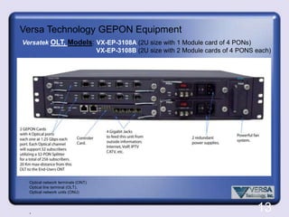
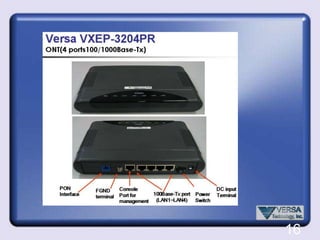
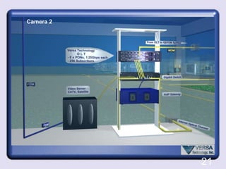
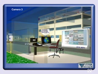
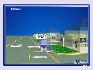
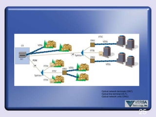
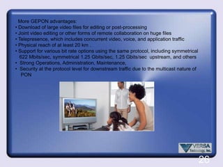
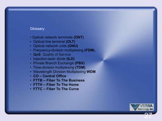
Presentation:  GEPON Technology  Brief introduction to Optical Fiber Technology (Please skip    slides 2 to 7 if you are already familiar with this topic)  Introduction to WDM (Wave Division Multiplexing)
  GEPON concept
Versa Technology GEPON equipment and sample.1
Brief overview of Optical Fiber Optical Fiber technology is a cutting edge method of sending and receiving information over great distances (150 km without using a repeater) using light as the data's carrier. The signal cannot be disrupted by outside sources like electricity, rain, humidity, or other things that tend to damage conventional copper wire signals.Fiber optic cables are composed of glass, silica Fiber, or plastic. Silica Fiber is used mainly for high power applications, and plastic is reserved for isolating sensitive systems from the threat of high voltages. Neither silica nor plastic are capable of sending data-streams over long distances because of their inherent impurities - instead, specialty glass fibers are used.Fiber optic systems offer high security because they do not induce or emit any external energy. A signal loss can be detected almost immediately as long as the system is monitored.Silica-silicon is most commonly found  in nature as sand or quartz.2
A fiber-optic system is similar to the copper wire system that fiber-optics is replacing. The difference is that fiber-optics use light pulses to transmit information down fiber lines instead of using electronic pulses to transmit information down copper lines. Components of a single optic fiber cable:µm, a micrometer (symbol µm) is one millionth of a meter, or equivalently one thousandth of a millimeter. It is also commonly known as a micron. It can be written in scientific notation as 1×10⁻⁶ m, meaning  1/1 000 000 m.3
At one end of the system is a transmitter. This is the place of origin for information coming on to fiber-optic lines. The transmitter accepts coded electronic pulse information coming from copper wire. It then processes and translates that information into equivalently coded light pulses. A light-emitting diode (LED) or an injection-laser diode (ILD) can be used for generating the light pulses. Using a lens, the light pulses are funneled into the fiber-optic medium where they travel down the cable. The light (near infrared) is most often 850nm for shorter distances and 1,300nm for longer distances on Multi-mode fiber and 1300nm for single-mode fiber and 1,500nm is used for longer distances.The attenuation peak in the vicinity of 1400 nm is due to residual water vapor in the glass fiver. However, new optical fiber designsremove the water peak in the 1400 nm region.nm = nanometer4
5
Note how as the pulse propagates down the fiber, the signal leaks into the cladding, indicating loss due to the micro-scale bend. In the image below, we plot the relative power loss (defined as the measured power in the core over the total power of the pulse) at 7 separate time intervals. As the pulse traverses the bend, the majority of the power is radiated into the cladding, and the remaining power still guided in the core diminishes rapidly as a function of time.6
Single Mode fibers have a small glass core, typically around 9μ. Single Mode fibers are used for high speed data transmission over long distances. They are less susceptible to attenuation than multimode fibers.Multimode fibers have large cores, usually either 50μ or 62.5μ. They are able to carry more data than single mode fibers though they are best for shorter distances because of their higher attenuation levels.7
Wavelength Division Multiplexing WDMA technique of sending signals of several different wavelengths of light into the fiber simultaneously. In fiber optic communications, wavelength-division multiplexing (WDM) is a technology which multiplexes multiple optical carrier signals on a single optical fiber by using different wavelengths (colors) of laser light to carry different signals. This allows for a multiplication in capacity, in addition to making it possible to perform bidirectional communications over one strand of fiber. 8
WDM is similar to frequency-division multiplexing (FDM). But instead of taking place at radio frequencies (RF), WDM is done in the IR portion of the electromagnetic (EM) spectrum. Each IR channel carries several RF signals combined by means of FDM or time-division multiplexing (TDM). Each multiplexed IR channel is separated, or demultiplexed, into the original signals at the destination. Using FDM or TDM in each IR channel in combination with WDM of several IR channels, data in different formats and at different speeds can be transmitted simultaneously on a single fiber.9
Sample, Dense Wavelength-division Multiplexing (DWDM): The transmission of many of closely spaced wavelengths in the 1550 nm region over a single optical fiber. Wavelength spacings are usually 100 GHz or 200 GHz which corresponds to 0.8 nm or 1.6 nm.Erbium-doped Fiber Amplifier (EDFA): Optical fibers doped with the rare earth element, erbium, which can amplify light in the 1550 nm region when pumped by an external light source.10
GEPON is an acronym for Gigabit Ethernet Passive Optical Network. It is called passive network because its distribution networks do not use electronic signal regeneration. Because optical fibers can replace bandwidth-restricted copper wires inexpensively, it is often referred to as “last mile” broadband solution for copper network replacement.Because light from a laser source can travel greater distance than electronic signal with less attenuation and its distribution network is consisted of passive elements, the cost of operations and maintenance in GEPON is greatly lower than traditional copper networks. For example, the capability to carry signals greater distance means less equipments, such as repeaters are needed; less equipments mean there are fewer points of failure in the network and fewer points of failure leads to improvement in network reliability and quality of service.A PON takes advantage of wavelength division multiplexing (WDM), using one wavelength for downstream traffic and another for upstream traffic on a single Nonzero dispersion shifted fiber (ITU-T G.652).  ITU-T G.652, Optical Standard, characteristic of a single-mode optical fiber  system. 11
Having passive components make up the distribution network means any future upgrade is cheaper and less painful because only the two end-point devices need be upgraded.12
Optical network terminals (ONT) Optical line terminal (OLT),Optical network units (ONU) ,13Versa Technology GEPON EquipmentVersatekOLT, Models: VX-EP-3108A(2U size with 1 Module card of 4 PONs)VX-EP-3108B (2U size with 2 Module cards of 4 PONS each)
14OAM(Operations, Administration and Maintenance)
Provide data link layer mechanisms for monitoring link
Use Slow Protocol
Objectives
Remote failure indication
Remote loopback
Link monitoring
Non-objectives
Management
Provisioning and negotiation
Authentication
Set/write remote MIB
core network inte IEEE 802.3ah compliant ODN      interface

GEPON Presentation

  • 1.
    Presentation: GEPONTechnology Brief introduction to Optical Fiber Technology (Please skip slides 2 to 7 if you are already familiar with this topic) Introduction to WDM (Wave Division Multiplexing)
  • 2.
    GEPONconcept
  • 3.
    Versa Technology GEPONequipment and sample.1
  • 4.
    Brief overview ofOptical Fiber Optical Fiber technology is a cutting edge method of sending and receiving information over great distances (150 km without using a repeater) using light as the data's carrier. The signal cannot be disrupted by outside sources like electricity, rain, humidity, or other things that tend to damage conventional copper wire signals.Fiber optic cables are composed of glass, silica Fiber, or plastic. Silica Fiber is used mainly for high power applications, and plastic is reserved for isolating sensitive systems from the threat of high voltages. Neither silica nor plastic are capable of sending data-streams over long distances because of their inherent impurities - instead, specialty glass fibers are used.Fiber optic systems offer high security because they do not induce or emit any external energy. A signal loss can be detected almost immediately as long as the system is monitored.Silica-silicon is most commonly found in nature as sand or quartz.2
  • 5.
    A fiber-optic systemis similar to the copper wire system that fiber-optics is replacing. The difference is that fiber-optics use light pulses to transmit information down fiber lines instead of using electronic pulses to transmit information down copper lines. Components of a single optic fiber cable:µm, a micrometer (symbol µm) is one millionth of a meter, or equivalently one thousandth of a millimeter. It is also commonly known as a micron. It can be written in scientific notation as 1×10⁻⁶ m, meaning 1/1 000 000 m.3
  • 6.
    At one endof the system is a transmitter. This is the place of origin for information coming on to fiber-optic lines. The transmitter accepts coded electronic pulse information coming from copper wire. It then processes and translates that information into equivalently coded light pulses. A light-emitting diode (LED) or an injection-laser diode (ILD) can be used for generating the light pulses. Using a lens, the light pulses are funneled into the fiber-optic medium where they travel down the cable. The light (near infrared) is most often 850nm for shorter distances and 1,300nm for longer distances on Multi-mode fiber and 1300nm for single-mode fiber and 1,500nm is used for longer distances.The attenuation peak in the vicinity of 1400 nm is due to residual water vapor in the glass fiver. However, new optical fiber designsremove the water peak in the 1400 nm region.nm = nanometer4
  • 7.
  • 8.
    Note how asthe pulse propagates down the fiber, the signal leaks into the cladding, indicating loss due to the micro-scale bend. In the image below, we plot the relative power loss (defined as the measured power in the core over the total power of the pulse) at 7 separate time intervals. As the pulse traverses the bend, the majority of the power is radiated into the cladding, and the remaining power still guided in the core diminishes rapidly as a function of time.6
  • 9.
    Single Mode fibershave a small glass core, typically around 9μ. Single Mode fibers are used for high speed data transmission over long distances. They are less susceptible to attenuation than multimode fibers.Multimode fibers have large cores, usually either 50μ or 62.5μ. They are able to carry more data than single mode fibers though they are best for shorter distances because of their higher attenuation levels.7
  • 10.
    Wavelength Division MultiplexingWDMA technique of sending signals of several different wavelengths of light into the fiber simultaneously. In fiber optic communications, wavelength-division multiplexing (WDM) is a technology which multiplexes multiple optical carrier signals on a single optical fiber by using different wavelengths (colors) of laser light to carry different signals. This allows for a multiplication in capacity, in addition to making it possible to perform bidirectional communications over one strand of fiber. 8
  • 11.
    WDM is similarto frequency-division multiplexing (FDM). But instead of taking place at radio frequencies (RF), WDM is done in the IR portion of the electromagnetic (EM) spectrum. Each IR channel carries several RF signals combined by means of FDM or time-division multiplexing (TDM). Each multiplexed IR channel is separated, or demultiplexed, into the original signals at the destination. Using FDM or TDM in each IR channel in combination with WDM of several IR channels, data in different formats and at different speeds can be transmitted simultaneously on a single fiber.9
  • 12.
    Sample, Dense Wavelength-divisionMultiplexing (DWDM): The transmission of many of closely spaced wavelengths in the 1550 nm region over a single optical fiber. Wavelength spacings are usually 100 GHz or 200 GHz which corresponds to 0.8 nm or 1.6 nm.Erbium-doped Fiber Amplifier (EDFA): Optical fibers doped with the rare earth element, erbium, which can amplify light in the 1550 nm region when pumped by an external light source.10
  • 13.
    GEPON is anacronym for Gigabit Ethernet Passive Optical Network. It is called passive network because its distribution networks do not use electronic signal regeneration. Because optical fibers can replace bandwidth-restricted copper wires inexpensively, it is often referred to as “last mile” broadband solution for copper network replacement.Because light from a laser source can travel greater distance than electronic signal with less attenuation and its distribution network is consisted of passive elements, the cost of operations and maintenance in GEPON is greatly lower than traditional copper networks. For example, the capability to carry signals greater distance means less equipments, such as repeaters are needed; less equipments mean there are fewer points of failure in the network and fewer points of failure leads to improvement in network reliability and quality of service.A PON takes advantage of wavelength division multiplexing (WDM), using one wavelength for downstream traffic and another for upstream traffic on a single Nonzero dispersion shifted fiber (ITU-T G.652). ITU-T G.652, Optical Standard, characteristic of a single-mode optical fiber system. 11
  • 14.
    Having passive componentsmake up the distribution network means any future upgrade is cheaper and less painful because only the two end-point devices need be upgraded.12
  • 15.
    Optical network terminals(ONT) Optical line terminal (OLT),Optical network units (ONU) ,13Versa Technology GEPON EquipmentVersatekOLT, Models: VX-EP-3108A(2U size with 1 Module card of 4 PONs)VX-EP-3108B (2U size with 2 Module cards of 4 PONS each)
  • 16.
  • 17.
    Provide data linklayer mechanisms for monitoring link
  • 18.
  • 19.
  • 20.
  • 21.
  • 22.
  • 23.
  • 24.
  • 25.
  • 26.
  • 27.
  • 28.
    core network inteIEEE 802.3ah compliant ODN interface