OCTG
Exploration
Tube
Technology
Tubing and casing
Pup-joint,x-over
Flow coupling
Drill pipe
Line pipe
Telephone +49 6592 71 20
Telefax +49 6592 13 05
Telex 4 729 937
P.O. Box 509
D - 54541 Daun/
F.R. Germany
Internet: www.TPS-Technitube.de or http://www.TPS-Technitube.com • e-mail: service@TPS-Technitube.de
---- OOOOCCCCTTTTGGGG ----
we connect
Made in GermanyMade in Germany
OCTG
HighQualitytubularproductsandaccessoriesOCTG
Tubing and casing
Pup-joint, x-over
Flow coupling
Drill Pipe
High Quality
tubular products
and accessories
High Quality
tubular products
and accessories
2.
Preface / Vorwort
TPS-TechnitubeRöhrenwerke GmbH ist ein leistungs-
starkes und zukunftsorientiertes Privatunternehmen mit
modernsten, weltweit anerkannten Produktionsstätten für
nahtlose Edelstahlrohre, Nickel, nickellegierte, Titan- und
titanlegierte Rohre, Ölfeldrohre und Gasförderrohre Bohr-
gestänge sowie oberflächenvergrößerte Rohre.
Die Produktionsbereiche der TPS-Technitube Röhrenwerke
GmbH, angesiedelt auf einer Gesamtindustriefläche von
über 60.000 m2
in Daun/Eifel im Zentrum Europas,
genießen weltweit den Ruf eines kompeten Herstellers von
Rohren höchster Qualität.
OCTG WERK
• Hersteller von Rohren und Rohrverbindungen für die
Erdöl- und Erdgasindustrie.
• TPS ist nach ISO 9001-2000 und API Q1 zertifiziert
und ist autorisiert zum Anwenden des API Mono-
gramm für Produkte nach API 5CT, API 5D und API
5L.
Von TPS hergestellte Verbinder:
• Steigrohre und Futterrohre gemäß API 5CT/5B
• Premium Verbinder:
TPS - MULTISEAL
TPS - TECHNISEAL
TPS - OPTIFLOW
• Pup Joints
X-Overs
Flow Couplings
Blast Joints
Coupulings usw.
• Bohrgestänge gemäß API 5D
• Leitungsrohre gemäß API 5L
TPS-Technitube Röhrenwerke GmbH is a privately
owned future orientated company operating up to date,
worldwide renowned production mills for oil- and gas-
field tubular products, Drill-Pipe for seamless tubes in
alloy steels, stainless steels, nickel, nickel alloys, titanium
and titanium alloys, for extended surface tubes, as well
as for special pipe and tubing products.
The TPS-Technitube Röhrenwerke production mills, located
in Daun/Germany in the centre of Europe, on an indu-
strial site of more than 660,000 sq. ft. have an excellent
reputation worldwide as a reliable and competent manu-
facturer of high quality pipe and tubular products and
accessories.
OCTG MILL
• Manufacturer of tubular products and accessories for
the oil and gas industry.
• TPS is certified to ISO 9001-2000 and API Q1 and is
licensed to use the API monogram on products manu-
factured according to API 5CT, API 5D and API 5L.
The connections manufactured by TPS are:
• Tubing and casing as per API 5CT
• Premium Joints:
TPS - MULTISEAL
TPS - TECHNISEAL
TPS - OPTIFLOW
• Pup Joints
X-Overs
Flow Couplings
Blast Joints
Couplings etc.
• Drill Pipes as per API 5D
• Line Pipe as per API 5L
2
OCTGgesamt A5 1-45 20.12.2002 12:51 Uhr Seite 2
3.
Contents / Inhalt
Hinweis:
DieAngaben in diesem Katalog sind nur zur allgemeinen
Information. Sie sind kein Ersatz für kompetente Fachhilfe,
welche für den jeweiligen Anwendungszweck benötigt
wird. Obwohl jede Maßnahme für die Genauigkeit der
Angaben getroffen wurde, gibt TPS keine Garantie für die
Vollständigkeit und Richtigkeit der Informationen, die in
diesem Katalog enthalten sind. Jeder, der diese Informa-
tionen benutzt, macht dies auf eigenes Risoko. TPS über-
nimmt keine Haftung für die Verwendung der Angaben
aus diesem Katalog.
Notice:
The material contained in this catalog is for general infor-
mation only. It is not intended as a substitute for the com-
petent professional assistance which is a requisite to any
specific application. While every effort has been made to
insure its accuracy, TPS makes no express or implied war-
ranty of any kind with respect to the information contained
in this publication or the materials referred therein. Anyo-
ne making use of the information or material therein does
so at their own risk and assumes any and all liability resul-
ting from such use.
3
•TPS API Tubing.............................................................................................4 - 17
•TPS API Casing...........................................................................................18 - 37
•TPS Optiflow Tubing & Casing ...............................................................38 - 45
•TPS Techniseal Tubing & Casing..............................................................46 - 47
TPS Techniseal Tubing..............................................................................48 - 59
TPS Techniseal Casing .............................................................................60 - 87
•TPS Multiseal Tubing & Casing ...............................................................88 - 89
TPS Multiseal Tubing TS8.........................................................................90 - 99
TPS Multiseal Tubing TS6.....................................................................100 - 103
TPS Multiseal TS4 Tubing & Casing.....................................................104 - 111
•TPS Multiseal Flush Joint ......................................................................112 - 115
•TPS Tubing & Casing Accessories .......................................................116 - 117
•TPS Drill Pipe ........................................................................................118 - 147
•TPS-Typical Grades for Tubing, Casing, Drill Pipe ............................148 - 151
• TPS Care & Use...................................................................................152 - 153
TPS Sicherheit & Gebrauch................................................................154 - 155
• TPS Conversion Factors for U.S./British and Metric Units
TPS Umrechnungsfaktoren für U.S./Britische und SI-Einheiten......156 - 159
OCTGgesamt A5 1-45 20.12.2002 12:51 Uhr Seite 3
4.
4
TPS API Tubing
-TBG
Tubing Non Upset Coupling Connection to API Spec. 5CT & 5B
- UPTBG
Tubing External Upset Coupling Connection to API Spec. 5CT & 5B
Option:
Special Clearance and
Special Bevel
20°
60°
End of Pipe
SR13 Resilient Seal Ring
Option:
Internal Transition Zone
Thread Run Out
and Face of Coupling
Taper 1 : 16
Round Thread Form
Option:
Special Clearance and
Special Bevel
20°
60°
End of Pipe
SR13 Resilient Seal Ring
Option:
Internal Transition Zone
Thread Run Out
and Face of Coupling
Taper 1 : 16
Ø 4” - 4 1/2” : 8 TPI
Ø 1.050” - 3 1/2” : 10 TPI
Round Thread Form
OCTGgesamt A5 1-45 20.12.2002 12:51 Uhr Seite 4
5.
TPS API Tubing
TPSAPI Tubing sind die Standard API Verbinder für die
Exploration.
Folgende Verbinder sind im Programm:
• Nichtgestauchte Steigrohre
1,050" - 3 1/2" 10 Gang Rundgewinde
4 - 4 1/2" 8 Gang Rundgewinde
• Aussen gestauchte Steigrohre
1,050" -1,900" 10 Gang Rundgewinde
2 3/8" -4 1/2" 8 Gang Rundgewinde
• Steigrohre mit Integralverbinder
1,315" - 2,063" 10 Gang Rundgewinde
Für spezielle Anforderungen sind auf Wunsch, technische
Änderungen der Standardangaben möglich.
Übliche Optionen sind:
Resilient Seal (SR 13) mit zusätzlichem Teflonring.
Special Clearance; für besondere Außendurchmesser Anfor-
derungen
Special Bevel; mit 20° Sonderfase
Die oben genannten Verbinder werden als Range 1/2/3
Rohre gefertigt. Ebenso sind Pup-Joints, X-Over, Flow Cou-
pling etc. gemäß Ihren technischen Wünschen herstellbar.
Rohre der gängigsten Abmessungen & Werkstoffe sind
meist lagermäßig lieferbar.
TPS API Tubing are the standard API threaded and cou-
pled connections for oil production.
The connections available are:
• Non upset tubing
1.050" - 3 1/2" round thread 10 tpi.
4 - 4 1/2" round thread 8 tpi.
• External upset tubing
1.050" - 1.900" round thread 10 tpi.
2 3/8" - 4 1/2" round thread 8 tpi.
• Integral joint tubing
1.315" - 2.063" round thread 10 tpi.
For special requirements, technical modifications to the
standard requirements are available.
Usual options are:
Resilient seal (SR 13) with an extra teflon ring seal.
Special clearance; for extra clearance applications
Special bevel; with 20° bevel
Above mentioned pipe can be produced in range 1,2 or 3.
We also produce pup-joints, X-overs, flow couplings and other
acessories according our customers`special technical requests.
We carry the most popular sizes and grades on stock for
immediate delivery to our customers.
5
OCTGgesamt A5 1-45 20.12.2002 15:24 Uhr Seite 5
6.
6
TPS API Tubing
12 3 4 5 6 7 8 9
Pipe Threaded and Coupled Connection
Size Nominal Weight Outside Diameter
O.D. Threaded and Coupled Wall Inside Drift Non Upset External Upset
Non Upset External Thickness Diameter API Regular Special
Upset Nominal Clearance
in. lb/ft in.
mm kg/m mm
1.050 1.14 1.20 0.113 0.824 0.730 1.313 1.660
26,7 1,70 1,79 2,87 20,9 18,54 33,4 42,2
1.050 1.54 0.154 0.742 0.648 1.660
26,7 2,29 3,91 18,8 16,46 42,2
1.315 1.70 1.80 0.133 1.049 0.955 1.660 1.900
33,4 2,53 2,68 3,38 26,6 24,26 42,2 48,3
1.315 2.24 0.179 0.957 0.863 1.900
33,4 3,34 4,55 24,3 21,92 48,3
OCTGgesamt A5 1-45 20.12.2002 12:51 Uhr Seite 6
16
TPS API Tubing
Couplingand Thread Dimensions for API-Tubing (Non-Upset)
̇ Optional 20° Special Bevel
̇ Optional Special Clearance
Optional SR 13 Resilient Seal Ring ̈
20°
1 2 3 4 5 6 7 8 9 10 11
Coupling Dimensions
Size Type Outside Length Diameter Depth Width of Hand-Tight End of Pipe No. of Weight
Outside of Ends Diameter of of Bearing Stand-off to Center Threads
Diameter Recess Recess Face of Coupling, per Inch
Regular Power-Tight
Make-Up
D W NL Q q b A J
in. in. Thread in. Ib
mm mm Turns mm kg
1.050 Non Upset 1.313 3 3/16 1.113 5/16 1/16 2 0.500 10 0.51
26,7 33,4 81,0 28,3 7,9 1,6 12,7 0,23
1.315 Non Upset 1.660 3 1/4 1.378 5/16 3/32 2 0.500 10 0.84
33,4 42,2 82,6 35,0 7,9 2,4 12,7 0,38
1.660 Non Upset 2.054 3 1/2 1.723 5/16 1/8 2 0.500 10 1.29
42,2 52,2 88,9 43,8 7,9 3,2 12,7 0,59
1.900 Non Upset 2.200 3 3/4 1.963 5/16 1/16 2 0.500 10 1.23
48,3 55,9 95,2 49,9 7,9 1,6 12,7 0,56
2 3/8 Non Upset 2.875 4 1/4 2.438 5/16 3/16 2 0.500 10 2.82
60,3 73,0 108,0 61,9 7,9 4,8 12,7 1,28
2 7/8 Non Upset 3.500 5 1/8 2.938 5/16 3/16 2 0.500 10 5.15
73,0 88,9 130,2 74,6 7,9 4,8 12,7 2,34
3 1/2 Non Upset 4.250 5 5/8 3.563 5/16 3/16 2 0.500 10 8.17
88,9 108,0 142,9 90,5 7,9 4,8 12,7 3,71
4 Non Upset 4.750 5 3/4 4.063 3/8 3/16 2 0.500 8 9.57
101,6 120,6 146,0 103,2 9,5 4,8 12,7 4,34
4 1/2 Non Upset 5.200 6 1/8 4.563 3/8 3/16 2 0.500 8 10.76
114,3 132,1 155,6 115,9 9,5 4,8 12,7 4,89
OCTGgesamt A5 1-45 20.12.2002 12:51 Uhr Seite 16
17.
17
TPS API Tubing
12 3 4 5 6 7 8 9 10 11 12 13
Coupling Dimensions Weight
Size Type Outside Diameter Length Diameter Depth Width of Hand-Tight End of Pipe No. of
Outside of Ends Regular Special of of Bearing Stand-off to Center Threads Regular Special
Diameter Clearance Recess Recess Face of Coupling, per Inch Clearance
Regular Power-Tight
Make-up
D W Wc NL Q q b A J
in. in. Thread in. Ib
mm mm Turns mm kg
1.050 External 1.660 -- 3 1/4 1.378 5/16 3/32 2 0.500 10 0.84 --
26,7 Upset 42,2 82,6 35,0 7,9 2,4 12,7 0,38
1.315 External 1.900 -- 3 1/2 1.531 5/16 3/32 2 0.500 10 1.26 --
33,4 Upset 48,3 88,9 38,9 7,9 2,4 12,7 0,57
1.660 External 2.200 -- 3 3/4 1.875 5/16 1/8 2 0.500 10 1.49 --
42,2 Upset 55,9 95,2 47,6 7,9 3,2 12,7 0,68
1.900 External 2.500 -- 3 7/8 2.156 5/16 1/8 2 0.500 10 1.85 --
48,3 Upset 63,5 98,4 54,8 7,9 3,2 12,7 0,84
2 3/8 External 3.063 2.910 4 7/8 2.656 3/8 5/32 2 0.500 8 3.42 2.29
60,3 Upset 77,8 73,9 123,8 67,5 9,5 4,0 12,7 1,55 1,04
2 7/8 External 3.668 3.460 5 1/4 3.156 3/8 7/32 2 0.500 8 5.29 3.33
73,0 Upset 93,2 87,9 133,4 80,2 9,5 5,6 12,7 2,40 1,51
3 1/2 External 4.500 4.180 5 3/4 3.813 3/8 1/4 2 0.500 8 9.02 5.08
88,9 Upset 114,3 106,2 146,0 96,9 9,5 6,4 12,7 4,10 2,31
4 External 5.000 -- 6 4.313 3/8 1/4 2 0.500 8 10.62 --
101,6 Upset 127,0 152,4 109,6 9,5 6,4 12,7 4,82
4 1/2 External 5.563 -- 6 1/4 4.813 3/8 1/4 2 0.500 8 13.31 --
114,3 Upset 141,3 158,8 122,3 9,5 6,4 12,7 6,04
Coupling and Thread Dimensions for API-Tubing (External-Upset)
̇ Optional 20° Special Bevel
̇ Optional Special Clearance
Optional SR 13 Resilient Seal Ring ̈
q
A
NL
J
20°
OCTGgesamt A5 1-45 20.12.2002 12:51 Uhr Seite 17
18.
TPS API Casing
18
-CSG/LCSG
Casing Short/Long Thread Coupling Connection to API Spec. 5CT 5B
- BCSG
Casing Buttress Thread Coupling Connection to API Spec. 5CT 5B
60°
End of Pipe
SR13 Resilient Seal Ring
Option:
Internal Transition Zone
Thread Run Out
and Face of Coupling
Taper 1 : 16
All Sizes : 8 TPI
Round Thread Form
Option:
Special Clearance and
Special Bevel
Buttress Thread Form
(_ 13 3/8)
All Sizes: 5 TPI
Taper 1: 16
End of Pipe
SR13 Resilient Seal Ring
Option:
Internal Transition Zone
Thread Run Out
and Face of Coupling
OCTGgesamt A5 1-45 20.12.2002 12:51 Uhr Seite 18
19.
TPS API Casing
19
TPSAPI Casing sind die Standard API Verbinder für die Explo-
ration.
• Futterrohre mit kurz oder lang Rundgewinde
4 1/2 - 20 8 Gang Rundgewinde
• Futterrohre mit Buttressgewinde
4 1/2 - 20 5 Gang Buttressgewinde
• Futterrohre mit Extreme Line Gewinde
5 - 7 5/8 buttress type thread 6 tpi
8 5/8 - 10 3/4 buttress type thread 5 tpi
Für spezielle Anforderungen sind auf Wunsch, technische Ände-
rungen der Standardangaben möglich.
Übliche Optionen sind:
Resilient Seal (SR 13) mit zusätzlichem Teflonring.
Special Clearance; für besondere Außendurchmesser Anforde-
rungen; Special Bevel; mit 20° Sonderfase
Die oben genannten Verbinder werden als Range 1/2/3
Rohre gefertigt. Ebenso sind Pup-Joints, X-Over, Flow Cou-
pling etc. gemäß Ihren technischen Wünschen herstellbar.
Rohre der gängigsten Abmessungen Werkstoffe sind
meist lagermäßig lieferbar.
TPS API Casing are the standard API threaded and coupled
connections for oil production.
• Round short or long thread casing
4 1/2 - 20 round thread 8 tpi.
• Buttress thread casing
4 1/2 - 20 buttress thread 5 tpi.
• Extreme line casing
5 - 7 5/8 buttress type thread 6 tpi
8 5/8 - 10 3/4 buttress type thread 5 tpi
For special requirements, technical modifications to the standard
requirements are available.
Usual options are:
Resilient seal (SR 13) with an extra teflon ring seal.
Special clearance; for extra clearance applications
Special bevel; with 20° bevel
Above mentioned pipe can be produced in range 1,2 or 3.
We also produce pup-joints, X-overs, flow couplings and other
acessories according our customers`special technical
requests.We carry the most popular sizes and grades on stock
for immediate delivery to our customers.
- Extreme Line
OCTGgesamt A5 1-45 20.12.2002 15:25 Uhr Seite 19
38
TPS Optiflow Tubing Casing
- Optiflow
Tubing and Casing Internal Flash Type Resilient Seal Connection
Option:
Special Bevel
Thread Run Out
and Face of Coupling
Buttress Type Thread
All Sizes : 5 TPI
Taper 1 : 16
Resilient Seal Ring
in the Internal
Transition Zone
Coupling Fillet
in the Internal
Transition Zone
10°
10°
3°
Option:
Special Clearance and
Special Bevel
20°
Thread Run Out
and Face of Coupling
60°
Round Thread Form
Non Upset
ø 1.900 - 3 1/2 : 10 TPI
ø 4 - 4 1/2 : 8 TPI
Ext. Upset
ø 2 3/8 - 4 1/2 : 8 TPI
Taper 1:16
Resilient Seal Ring
in the Internal
Transition Zone
Coupling Fillet
in the Internal
Transition Zone
OCTGgesamt A5 1-45 20.12.2002 12:51 Uhr Seite 38
39.
TPS Optiflow Tubing Casing
TPS-OPTIFLOW ist die wirtschaftliche Empfehlung für alle Tubing
und Casing Einsatzfälle, bei denen:
• Der störende Einfluß der Fließturbulenzen eliminiert werden
soll.
• Innenbeschichtete Rohre zum Einsatz kommen.
Zum Beispiel:
Verbesserte Erosions- und Korrosionsbeständigkeit.
Verbesserte hydraulische Eigenschaften.
Verminderung von Ablagerungen.
Reinheit von Flüssigkeiten.
Merkmale:
• Pin zu Pin Brücke eliminiert die Fließturbulenzen durch ein nahe-
zu glatten Innenübergang.
• Speziell profilierte Teflon-Dichtring im stärksten Muffenbereich
verhindert das Eindringen des Fördermediums in den Gewin-
debereich.
• Teflon-Dichtring schützt auch beim Verschrauben die Rohr- und
Muffenbeschichtung und verhindert eine sonst mögliche
Beschädigung.
Nachfolgend einige Beispiele für den Einsatz von TPS OPTIFLOW
Muffen:
• Tubing zur Erdölförderung.
• Innenbeschichtete Tubing zur Erdölförderung.
• Innenbeschichtete Injektionsleitung.
• Innenbeschichtete Produktions-Casing.
• Salzwasserförderung.
• Rückfüllrohr für Stollenverfüllung im Salzbergwerk.
• Granulattransportleitung, sowohl horizontal als auch vertikal in
der Bergwerkindustrie.
Für spezielle Anforderungen sind auf Wunsch, technische Ände-
rungen der nachfolgenden Optionen möglich.
Übliche Optionen sind:
Special Clearance für besondere Außendurchmesser Anforderungen
auf Anfrage
Special Bevel; mit 20° Sonderfase
Folgende Abmessungen Gewindearten sind im Programm:
• Nichtgestauchte Steigrohre
1,9 - 3 1/2 10 Gang Rundgewinde
2 3/8 - 4 1/2 8 Gang Rundgewinde
• Aussen gestauchte Steigrohre
1,9 10 Gang Rundgewinde
2 3/8 -4 1/2 8 Gang Rundgewinde
• Futterrohre mit kurz oder lang Rundgewinde
4 1/2 - 13 3/8 5 Gang Buttressgewinde
Die oben genannten Verbinder werden als Range 1/2/3 Rohre gefertigt.
Ebenso sind Pup-Joints, X-Over, Flow Coupling etc. gemäß Ihren technischen
Wünschen herstellbar.
Rohre der gängigsten Abmessungen Werkstoffe sind meist lagermäßig
lieferbar.
TPS-OPTIWLOW is the recommendation for an economic tubing
and casing connection, for all applications where:
• Flow turbulences have to be eliminated.
• Internally coated pipe is to be used.
For example:
For corrosion resistance
Improved hydraulic properties
Reduction of deposits
Purity of liquids
Characteristics:
• Pin to pin recess bridge eliminates flow turbulences by its prac-
tically smooth transition area.
• Specially profiled teflon seal ring in the strongest part of the cou-
pling impedes attack from the medium of the threaded area.
• Teflon seal ring also protects the pipe and coupling coating
from damage during power tight make up.
Below some examples for the application of
TPS OPTIFLOW couplings:
• Tubing for crude oil production.
• Internally coated tubing for crude oil production.
• Internally coated injection line.
• Internally coated production casing.
• Salt water transportation.
• Refill pipe for refilling mining galleries in salt mines.
• Transportation of granulate horizontally as well as vertically in
the mining industry.
For special requirements, technical modifications to the standard
requirements are available.
Usual options are:
Special clearance for extra clearance applications
Special bevel; with 20° bevel on request.
The following sizes and connections are included in aur delivery-
programme:
• Non upset tubing
1,9 - 3 1/2 10 round threads per inch
2 3/8 - 4 1/2 8 round threads per inch
• External upset tubing
1,9 10 round threads per inch
2 3/8 - 4 1/2 8 round threads per inch
• Casing
4 1/2 - 13 3/8 5 threads per inch / Buttress
Above mentioned pipe can be produced in range 1,2 or 3.
We also produce pup-joints, X-overs, flow couplings and other acessories accor-
ding our customers`special technical requests.
We carry the most popular sizes and grades on stock for
immediate delivery to our customers.
39
OCTGgesamt A5 1-45 20.12.2002 15:26 Uhr Seite 39
42
TPS Optiflow Tubing Casing
Wir empfehlen den Einsatz von TPS OPTIFLOW Muffen
in Verbindung mit Original TPS Tubing oder TPS Casing.
Diese werden mit einer Verschraubungsmarkierung für
leichtes und exaktes Verschrauben geliefert. Ein hohes
Maß an Flexibilität innerhalb der TPS OCTG Fertigung
gewährleistet, daß eilige Bedarfsfälle und spezielle
technische Problemstellungen auch mit Sonderlösungen
realisiert werden können.
Nachfolgend einige Beispiele für den Einsatz von
TPS OPTIFLOW Muffen:
• Tubing zur Erdölförderung
• Tubing innenbeschichtet zur Erdölförderung
• Innenbeschichtete Injektionsleitung
• Innenbeschichtete Produktions-Casing
• Salzwasserförderung (unbeschichtet)
• Als Rückfüllrohrtour für Stollenverfüllung
im Salzbergwerk
• Granulattransportleitung, sowohl horizontal
als auch vertikal in der Bergwerkindustrie
We recommend the use of TPS OPTIFLOW couplings
together with Original TPS Tubing or TPS Casing. These
are supplied with a make up triangle for easy and exact
power tight make up. A high degree of flexibility in the
TPS OCTG production guarantees that urgent
requirements and problems requiring special solutions
can be solved.
Below some examples for the application of TPS
OPTIFLOW couplings:
• Tubing for crude oil production
• Internally coated tubing for crude oil production
• Internally coated injection line
• Internally coated production casing
• Salt water transportation (uncoated)
• As refill pipe for refilling mining galleries in salt mines
• Transportation of granulate horizontally as well as ver-
tically in the mining industry
OCTGgesamt A5 1-45 20.12.2002 12:51 Uhr Seite 42
43.
43
TPS Optiflow Tubing Casing
Innenbeschichtung von TPS OPTIFLOW:
In Zusammenarbeit mit der Tuboscope Vetco bieten wir
innenbeschichtete Tubing Casing an. Das Design der
TPS OPTIFLOW Muffen ist dazu so ausgelegt, daß die
Vorteile der Innenbeschichtung auch im sonst kritischen
Verbinderbereich den vollen Nutzen bringt, d. h. optima-
len Korrosionsschutz im Übergang Rohr-/Muffe und
erhebliche Verbesserung der hydraulischen Eigenschaf-
ten über die volle Stranglänge. Dies erschließt Anwen-
dungen, wo sonst nur erheblich teurere Werkstoffe und
Ausführungen verwendet werden, oder erhebliche Stand-
zeitprobleme bestehen wie z. B. bei der Soleförderung
oder sonstigen, aggressiven Medien. Die Verbesserung
der hydraulischen Eigenschaften wird erreicht, indem die
Beschichtung auf die zuvor entzunderte und gereinigte
Oberfläche aufgebracht wird und im Fertigzustand
medienseitig eine extrem glatte Oberfläche erzielt wird.
Dies ergibt Produktivitätsverbesserungen von bis zu 20%.
Durch einen sogenannten Holiday Test wird sicherge-
stellt, daß die Beschichtung im ganzen Rohrstrang lücken-
los und porenfrei ist. Die Beschichtung vermindert erheb-
lich Angriffsmöglichkeiten für Ablagerungen, so daß Nei-
gung zum Verstopfen auf ein Minimum reduziert ist. Rapi-
der Druckabfall von über 500 bar und Temperaturen bis
200°C werden von der Beschichtung ohne Funktionsein-
bußen überstanden, da die Verbindung mit dem Basis-
rohr aufgrund der Materialeigenschaften auch unter
extremen Bedingungen erhalten bleibt.
Internal Coating of TPS OPTIFLOW
We offer together with Tuboscope Vetco internally coated
tubing and casing. TPS OPTIFLOW Couplings have been
designed so that the advantages of internal coating can
be fully applied, even in the critical connection area. This
means that there is an optimum corrosion protection in the
pipe to coupling transition area and much improved
hydraulic properties over the complete string length. This
includes uses, where otherwise much more expensive steel
grades and connections would have to be used, or there
would be much shorter lifetimes e.g. by the transport of
saline solutions or other aggressive mediums. The impro-
ved hydraulic properties are achieved, in that the coating
is applied to the descaled and cleaned surfaced. The
coating surface achieved is extremely smooth. This impro-
ves productivity by up to 20%. The Holiday Test ensures
that the coating over the whole length is complete and
free of pores. The internal coating reduces the possibility
of deposits to a minimum and therefore that of stoppages
as well. Rapid pressure drops from over 500 bar and
temperature drops up to 200°C will not affect the func-
tion of the internal coating, since the bonding of the coa-
ting to the pipe, due to its properties, remains even under
extreme conditions.
OCTGgesamt A5 1-45 20.12.2002 12:51 Uhr Seite 43
44.
44
TPS Optiflow Tubing Casing
TPS OPTIFLOW End
with make-up position tri-
angle
TPS OPTIFLOW
Seal Ring
TPS OPTIFLOW
Coupling
Seal Ring
Pre-forming
Verschraubungsanweisung für:
TPS OPTIFLOW Kupplungen
• Die Gewinde müssen vor dem Einbau PIN- und
BOX-seitig gereinigt werden. Die “Anti Galling
Schicht” darf dabei nicht beschädigt werden.
• Die feldseitig einzubauenden TPS OPTIFLOW
Dichtringe müssen ebenfalls sauber sein und sind
zum Einsetzen nierenförmig zu formen (nicht
knicken oder scharf biegen).
• Die so geformten Dichtringe sind dann, korrekt posi-
tioniert, in die saubere Dichtringnut einzulegen und
rundum anliegend, kreisrund zurückzuformen. Der
Einbau ist korrekt, wenn die Planfläche des Dichtrin-
ges nicht mehr sichtbar ist bzw. darf die Planfläche
des Dichtringes nicht nach innen aus dem Gewinde
hervorstehen.
• Die Gewinde sind vollständig und gleichmäßig (Pin
Box) mit sauberem Gewindefett gem. API-BUL
5A2 dünn zu befetten.
• Beim Einschrauben ist darauf zu achten, daß Rohr
und Muffe zueinander fluchten, die Verschraub-
zange in Bohrlochnähe aufgehängt ist und daß
keine “Crossverschraubung” oder Beschädigungen
entstehen.
• Rohr und Muffe sind mindestens soweit zusammen-
zuschrauben, daß die Muffenplanfläche mit der
Dreieckbasis der Verschraubungsmarkierung
deckungsgleich ist. Die Maximalverschraubung ist
erreicht, wenn die Muffenplanfläche die Dreieckba-
sis 1
2 Umdrehung überdeckt.
OCTGgesamt A5 1-45 20.12.2002 13:57 Uhr Seite 44
45.
45
TPS Optiflow Tubing Casing
Press the Seal Ring into
the Groove
Seal Ring correctly
fitted
Handtight
Make-up
Make Up Running Procedure for:
TPS OPTIFLOW Couplings
• The threads must be cleaned before make up. The
anti galling coating must not be damaged.
• The TPS OPTIFLOW seal ring that is to be fitted into
the field end of the coupling must be formed to a
kidney shape (do not buckle).
• The seal ring is then to be placed into the clean
seal ring groove and pressed fully into it. The ring
has been correctly fitted, when the face of the ring
is not visible above the groove i.e. the face of the
ring is not allowed to stand out into centre of the
coupling.
• The threads (Pin Box) are to be doped fully in a
thin even layer with clean thread dope acc. to
API BUL 5A2.
• On stabbing, the pipe must line up with the
coupling. The power tongs must be hanging close
to the borehole and care taken that the connection
is not cross threaded or damaged.
• The Pin and Box are to be made up so that the face
of the box reaches to the base of the make up tri-
angle. The maximum make up is reached when the
face of the box is 1
2 turn past the base of the make
up triangle.
OCTGgesamt A5 1-45 20.12.2002 12:51 Uhr Seite 45
46.
46
TPS Techniseal Tubing Casing
- Techniseal
Tubing and Casing Non Upset Premium Coupling Connection
3°
10°
20°
20°
30°
15°
1:10
Thread Run Out
and Face of Coupling
Option:
Special Clearance
Special Bevel
Buttress Type Thread Form
ø 2 3/8 - 2 7/8 : 8 TPI
ø 3 1/2 - 4 1/2 : 6 TPI
ø 5 - 13 3/2 : 5 TPI
Taper 1 : 16
Option:
Resilient Seal Ring
30° Metal to Metal
Pressure Seal and
20° Reverse Angle
Torque Shoulder
1 : 10 Metal to Metal
Pressure Seal and
15° Positive
Torque Shoulder
Coupling Fillet in the
Internal Transition Zone
OCTGgesamt 46-87 20.12.2002 12:57 Uhr Seite 46
47.
TPS Techniseal Tubing Casing
Die TPS-Techniseal Verbindung ist eine flexibel einsetz-
bare, hochbelastbare nicht gestauchte gasdichte Muffen-
verbindung für Tubing und Casing. Geeignet zum Einsatz
unter den verschiedensten Bedingungen.
Zum Beispiel bei:
hohen Drücken
hohen Temperaturen
abgelenkten bzw. horizontalen Bohrungen
tiefen Bohrungen
hochagressiven Bedingungen
Merkmale:
• metallischer Gasdichtsitz
Tubing: 30° Dichtfläche
Casing: 10% kegelige Dichtfläche
• verbesserte Buttress Gewindeform resistent gegen
Gewindefresser
• Gewindekopfspiel garantiert eine gleichmäßige Vertei-
lung des Gewindefettes beim Verschrauben.
• Außendurchmesser der Muffen meist kleiner als nach
API.
• das stromlinienförmige Innenprofil der Verbindung
ergibt einen excellenten Übergang zwischen Rohr und
Muffe. Fließturbulenzen, Druckverluste und Korrosion
werden auf ein Minimum reduziert.
• der lange Steg in der Muffe garantiert eine gute Span-
nungsverteilung in der Verbindung.
• durch die günstige Spannungsverteilung im kraftver-
schraubten Verbinder wird erheblich die Neigung zur
wasserstoffinduzierten Spannungsrisskorrosion vermin-
dert.
• Joint efficiency beträgt bei üblichen Einsatzbedingungen
100%*.
• sehr gute Verschraubungshandhabung durch großen
Toleranz-bereich, sowie optimal ausgelegte Drehmo-
mente.
Für spezielle Anforderungen sind auf Wunsch, technische
Änderungen der nachfolgend Standardangaben möglich.
Übliche Optionen:
Matched Stength; für Starkwand Casing zum Erreichen
der 100% Verbinderbelastbarkeit
Special Clearance; für besondere Außendurchmesser Anforderun-
gen
Special Bevel; mit 20° Sonderfase
Resilient Seal; mit zusätzlichem Teflonring
* Ausnahme einige Starkwand Casing
Die oben genannten Verbinder werden als Range 1/2/3 Rohre gefertigt.
Ebenso sind Pup-Joints, X-Over, Flow Coupling etc. gemäß Ihren technischen
Wünschen herstellbar.
Rohre der gängigsten Abmessungen Werkstoffe sind meist lagermäßig
lieferbar.
The TPS-Techniseal tubing and casing joints are a versati-
le high performance non upset premium gastight coupling
connection. Suitable for use in a combination of environ-
ments and well conditions.
For example:
high pressures
high temperatures
deviated and horizontal wells
deep wells
highly corrosive environments
Characteristics:
• metal to metal gas tight seal
tubing: 30° seal angle
casing: 10% taper seal
• improved buttress thread form resistant to galling.
• relief between pin crest and box root assures communi-
cation through the joint avoids trapping of compound.
• coupling outside diameter often smaller than API
• streamlined internal connection profile gives. an excel-
lent match between pin bore and coupling centre bore,
turbulence, pressure losses and corrosion are reduced
to a minimum.
• long centre fillet in the coupling for good stress distri-
bution in the joint
• the stress distribution in the pin of the made up joint
greatly reduces the susceptibility to hydrogen embrittle-
ment.
• the joint effeciency is 100% with respect to the pipe
body in all normal modes*.
• excellent make up properties due to wide and well defi-
ned torque values.
For special requirements, technical modifications to the
standard requirements are available.
Usual options are:
Matched strength; for 100% tensile efficiency of heavy
wall casing
Special clearance; for extra clearance applications
Special bevel; with 20° bevel
Resilient seal; with an extra teflon ring seal
* except for some heavy wall casing
Above mentioned pipe can be produced in range 1,2 or 3.
We also produce pup-joints, X-overs, flow couplings and other acessories accor-
ding our customers`special technical requests.
We carry the most popular sizes and grades on stock for
immediate delivery to our customers.
47
OCTGgesamt 46-87 20.12.2002 15:26 Uhr Seite 47
88
TPS Multiseal Tubing Casing
- MULTISEAL TS 8 / TS 8 TR
Tubing External Upset High Performance Premium Integral Connection
- MULTISEAL TS 6 / TS 6 TR
Tubing External Upset High Performance Premium Integral Connection
- MULTISEAL TS 4 / TS 4 TR
Casing External Upset High Performance Premium Integral Connection
Positive 30°
Torque Shoulder
and Metal to Metal
Pressure Seal
2 Step Design
Two Different
Thread Diameters
and 90° Shoulder
14° Internal
Metal to Metal
Pressure Seal and
Internal Recess Free
Transition Zone
Design TR
14° Internal
Metal to Metal
Pressure Seal with
Resilient Seal Ring
Recess Free In the
Internal Transition Zone
90°
30°
7.5°
20°
14°
Buttress Type Thread Form
1,05 - 4 1/2 : 8 TPI
2 3/8 - 4 1/2 : 6 TPI
5 - 7 : 4 TPI
OCTGgesamt 88-117 20.12.2002 14:44 Uhr Seite 88
89.
TPS Multiseal Tubing Casing
Die TPS-Multiseal Tubing und Casing Verbindung ist eine
seit langem bewährte nach aussen gestauchte gasdichte
zweistufen Integral-Premiumverbindung. Sie wird den höch-
sten Ansprüchen an Anwenderfreundlichkeit und Zuverläs-
sigkeit gerecht und ist geeignet zum Einsatz unter den
verschiedensten Bedingungen.
Zum Beispiel bei:
hohen Drücken
hohen Temperaturen
abgelenkten bzw. horizontalen Bohrungen
tiefen Bohrungen
hochagressiven Bedingungen
widrigen Einsatzbedingungen
Merkmale:
• 14° Metallischer Gasdichtsitz gegen inneren Überdruck.
• 30° Metallischer Gasdichtsitz gegen aüßeren und
inneren Überdruck und Torqueschulter.
• 90° Torqueschulter und 30° Dicht und Torqueschulter
schutzen gegen überschrauben.
• Zwei Stufen verbesserte zylindrische Buttress Gewinde-
form.
• Keine Gewindeüberdeckung vorhanden, somit keine
Neigung zum Gewindefressen.
• Außendurchmesser der Verbinder ist kleiner als nach API.
• Stabiles Einsetzen des Pinendes auf zwei Gewinde-
flanken.
• Schnelles Verschrauben.
• Das stromlinienförmige Innenprofil der Verbindung
ergibt einen excellenten Übergang zwischen Pin und
Box. Fließturbulenzen, Druckverluste und Korrosion wer-
den auf ein Minimum reduziert.
• Joint Efficiency ist bei allen Verbindungen größer 100%.
• Integralausführung halbiert die Anzahl der
Gewindeverbindungen. (keine Werksverschraubung)
• sehr gute Verschraubungshandhabung durch großen
Toleranzbereich, sowie optimal ausgelegte Drehmo-
mente.
• Wiederholbare dichtigkeitseigenschaften bei Mehr-
fachverschraubung.
Für spezielle Anforderungen sind auf Wunsch technische
Änderungen der nachfolgend Standardangaben möglich.
Übliche Optionen sind:
Besonders lange Upsets für mehrfache Nachschneidbar-
keit sind auf speziellen Wunsch möglich.
TR Option mit Teflon Ring optimal fur Innenbeschichtun-
gen, verhindert ein Eindringen aggressiver Medien in das
Dicht- bzw. Gewindesystem.
Special Clearance; für besondere Außendurchmesser
Anforderungen
Die oben genannten Verbinder werden als Range 1/2/3 Rohre gefertigt.
Ebenso sind Pup-Joints, X-Over, Flow Coupling etc. gemäß Ihren technischen
Wünschen herstellbar.
Rohre der gängigsten Abmessungen Werkstoffe sind meist lagermäßig
lieferbar.
The TPS-Multiseal tubing and casing connection is an
external upset two step integral gastight premium joint
proven over many years. It fulfils the highest requirements
for reliability and easy handling and is suitable for use in
a combination of environments and well conditions.
For example:
high pressures
high temperatures
deviated and horizontal wells
deep wells
highly corrosive environments
severe well condition
Characteristics:
• 14° metal to metal gas tight internal pressure seal.
• 30° metal to metal gas tight internal external pressure
seal and torque shoulder.
• 90° torque shoulder and 30° seal and torque shoulder
provide effective protection against overtorquing.
• Two step improved non tapered buttress type thread
form.
• No thread interference, so no tendency to thread
galling.
• Connection outside diameter smaller than API.
• Stable two thread flank stabbing, cannot be cross
threaded
• Fast make up.
• Streamlined internal connection profile giving an excel-
lent match between pin and box bores, turbulence,
pressure losses and corrosion are reduced to a mini-
mum.
• The joint effeciency is greater than 100% for all
connections.
• Integral connection halves the number of threaded
connections (no mill connection).
• Easy handling during make up, due to large tolerances
as well as optimal torque values.
• Repeatable sealing capability on multiple make and
breaks.
For special requirements, technical modifications to the
standard requirements are available.
Usual options are:
Etreme long upsets are available on request for multiple
re-threading.
TR option with teflon ring, perfectly suited for internal coa-
ting, which protects the sealing and thread systems against
corrosive mediums.
Special clearance; for extra clearance applications
Above mentioned pipe can be produced in range 1,2 or 3.
We also produce pup-joints, X-overs, flow couplings and other acessories accor-
ding our customers`special technical requests.
We carry the most popular sizes and grades on stock for
immediate delivery to our customers.
89
OCTGgesamt 88-117 20.12.2002 15:27 Uhr Seite 89
112
TPS Multiseal FlushJoint
- Multiseal Flush Joint
Tubing and Casing Non Upset Integral Flush Joint Premium Connection
30°
14°
30°
90°
20°
5°
14°
Positive 30°
Torque Shoulder and
Metal to Metal Seal
Design S
14° external pressure seal
with relief grooves on 30°
torque Shoulder
2 Step Design and
two Different Diameters
Thread Form
ø 2 3/8 - 4 1/2 : 8 TPI
ø 5 - 7 5/8 : 6 TPI
ø 8 5/8 - 9 5/8 : 4 TPI
14° Internal Metal to Metal
Pressure Seal
OCTGgesamt 88-117 20.12.2002 14:44 Uhr Seite 112
123.
TPS Multiseal FlushJoint
Die TPS-Multiseal Flush Joint Tubing und Casing Ver-
bindung ist eine Non Upset Zweistufen Integral-Verbin-
dung. Es ist für den Einsatz als Liner und bei Casing bis zu
mittleren Tiefen geeignet.
Merkmale:
• 14° Metallischer Dichtsitz gegen inneren Überdruck.
• 30° Metallischer Dichtsitz gegen aüßeren und inneren
Überdruck und Torqueschulter.
• Durchgehende AD und ID für maximale Abstände im
Ringraum sowie beim Ein- und Ausbau.
• Pin- und Box Gewinde werden direkt in die Wand
geschnitten, keine Kupplung notwendig.
• Beschädigte Gewinde können einfach abgetrennt und
neu geschnitten werden.
• Zwei Stufen zylindrische Buttress Typ- Gewindeform.
• Keine Gewindeüberdeckung vorhanden, so keine Nei-
gung zum Gewindefressen.
• Stabiles Einsetzen des Pinendes auf zwei Gewinde-
flanken.
• Crossverschrauben nicht möglich.
• Schnelles Verschrauben.
• Integralausführung halbiert die Anzahl der
Gewindeverbindungen. (keine Werksverschraubung)
• Die Außendruckfestigkeit des Verbinders ist größer als
die des Basisrohres.
• Wiederholbare Dichtigkeitseigenschaften bei Mehr-
fachver-schraubung.
Die oben genannten Verbinder werden als Range 1/2/3 Rohre gefertigt.
Ebenso sind Pup-Joints, X-Over, Flow Coupling etc. gemäß Ihren technischen
Wünschen herstellbar.
Rohre der gängigsten Abmessungen Werkstoffe sind meist lagermäßig
lieferbar.
The TPS-Multiseal Flush Joint Tubing and Casing connec-
tion is a non upset two step integral joint, suitable for use
as liners and moderate depth casing.
Characteristics:
• 14° metal to metal internal pressure seal.
• 30° metal to metal internal external pressure seal and
torque shoulder.
• Completely flush OD and ID for maximum annular and
running clearances.
• Pin and Box threads machined directly into pipe wall,
no coupling required.
• Damaged threads can be simply cut off and
remachined
• Two step non tapered buttress type thread form.
• No thread interference, so no tendency to thread
galling.
• Stable two thread flank stabbing.
• Cannot be cross threaded.
• Fast make up.
• Integral connection halves the number of threaded
connections (no mill connection).
• External pressure integrity in excess of pipe body.
• Repeatable sealing capability on multiple make and
breaks.
Above mentioned pipe can be produced in range 1,2 or 3.
We also produce pup-joints, X-overs, flow couplings and other acessories accor-
ding our customers`special technical requests.
We carry the most popular sizes and grades on stock for
immediate delivery to our customers.
113
OCTGgesamt 88-117 20.12.2002 15:28 Uhr Seite 113
TPS Tubing Casing Accessories
Das TPS OCTG fertiger Rohren Produktionswerk unter-
hält ein umfangreiches Lager von Zubehörteilen mit und
ohne Premiumverbinder.
Die standard Zubehörteile sind:
Passstangen
Cross Overs
Blast Joints
Flow Couplings
Muffen
Zubehörteile sind in üblichen Werkstoffgüten, mit den
verschiedenen Verbindertypen aus unserem Produktions-
programm oder Kombination hiervon, lieferbar.
Andere Verbindertypen und Zubehörteile, die nicht zu
unserem standard Produktionsprogramm gehören,
können auch auf Anfrage geliefert werden.
In Zusammenarbeit mit unseren Vertragspartnern können
wir komplette Down-Hole-Equipments sowie entsprechen-
de Bearbeitung im Rahmen unseres Services anbieten.
TPS hat weltweit Reparaturbetriebe lizenziert, um TPS Ver-
binder nachzuschneiden oder Adapter herzustellen.
Die oben genannten Verbinder werden als Range 1/2/3 Rohre gefertigt.
Ebenso sind Pup-Joints, X-Over, Flow Coupling etc. gemäß Ihren technischen
Wünschen herstellbar.
Rohre der gängigsten Abmessungen Werkstoffe sind meist lagermäßig
lieferbar.
The TPS OCTG Production Department keeps a large
stock of premium connection and non premium connection
accessories in stock.
The standard accessories in our Program are:
Pup Joints
Cross Overs
Blast Joints
Flow Couplings
Couplings
Accessories are available in the standard grades, with
any of the connection types or combinations thereof, that
are in our production program.
Other proprietary connections and accessories, that are
not part of our standard program, can be supplied on
request.
Im cooperation with our partners we can supply complete
downhole equipment as well as the respective handling
within our service package.
TPS has also licensed thread repair workshops to rethread
or manufacture TPS proprietary connections.
Above mentioned pipe can be produced in range 1,2 or 3.
We also produce pup-joints, X-overs, flow couplings and other acessories accor-
ding our customers`special technical requests.
We carry the most popular sizes and grades on stock for
immediate delivery to our customers..
117
OCTGgesamt 88-117 20.12.2002 15:28 Uhr Seite 117
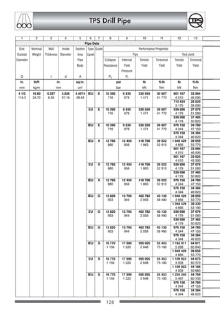
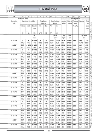
128.
TPS Drill Pipe
118
*90° shoulder on request
Internal Upset
IU
External Upset
EU
Internal-External Upset
IEU
OCTGgesamt A5 118-160 20.12.2002 13:09 Uhr Seite 118
129.
TPS Drill Pipe
TPSDrill Pipe für die Verwendung in der Öl- und Gas-
Exploration und Produktion sind in den nachfolgend
aufgelisteten Abmessungen und Stauchungen gemäß API
5D erhältlich. Andere Abmessungen und Stauchungen
werden auf Anfrage geliefert.
In Zusammenarbeit mit unseren Partnern, können wir
Bohrgestänge mit reibgeschweissten Tool Joints liefern.
Bohrgestänge Abmessungen:
2 3/8 - 6 5/8
Stauchformen:
Aussengestaucht EU
Innengestaucht IU
Innen- und Aussengestaucht IEU
Reibgeschweisste Tool Joints
Numbered Connections NC
Internal Flush IF
Full Hole FH
Für spezielle Anforderungen sind auf Wunsch, technische
Änderungen der Standardangaben möglich.
Übliche Optionen sind:
Tool Joint Hard Facing (Hartpanzerung); verlängert die
Lebens-dauer des Tool Joints.
Innenbeschichtung: verhindert Korrosion und verbessert
die hydraulische Effizienz und somit wird die Abnutzung
innen reduziert.
Für ausführliche Informationen, verweisen wir Sie
auf unseren TPS DRILL PIPE Katalog.
TPS Drill Pipe for application in the oil and gas explorati-
on and production industry are available in all sizes and
upset ends according to API 5D. Other sizes and upsets
are supplied on request.
Together with our partners we can supply the drill pipe
with friction welded Tool Joints, ready for use.
Drill Pipe Size Range:
2 3/8 - 6 5/8
Upset Types:
External Upset EU
Internal Upset IU
Internal External Upset IEU
Friction welded Tool Joints:
Numbered Connections NC
Internal Flush IF
Full Hole FH
For special requirements, technical modifications to the
standard requirements are available.
Usual options are:
Hard Facing of Tool Joints; to increase life of Tool Joints.
Internal Coating; avoids corrosion and improves
hydraulic efficiency thus reducing internal wear.
For more detailed information, please refer to
our TPS DRILL PIPE catalogue.
119
OCTGgesamt A5 118-160 20.12.2002 13:09 Uhr Seite 119
142
TPS Drill Pipe
DrillPipe Marking
The following marks are applied as standard to the drill pipe body.
Paint stenciling on Pipe Body
Exmple
Tool Joint Marking
The following marks are applied as standard to the tool joints.
Die stamping on Pin and Box End
SK Spec. 5 D 01 / 03
Manufacturer‘s Symbol Specification Date of Manufacture
3 1/2” x 15.50 lb/ft S 135 x y
Size x Weight Grade Heat Number or Heat Code
Example
Other Marking can be performed on request.
253 SK VPI 23.03
Serial Number Manufacturer‘s Symbol Part Number
01 / 03 NC 38 (3 1/2“ IF) x y
Date of Manufacture Connection Heat Number or Heat Code
OCTGgesamt A5 118-160 20.12.2002 13:09 Uhr Seite 142
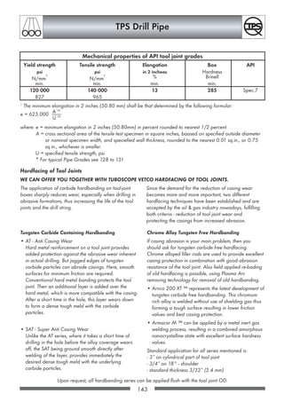
153.
143
TPS Drill Pipe
Hardfacingof Tool Joints
WE CAN OFFER YOU TOGETHER WITH TUBOSCOPE VETCO HARDFACING OF TOOL JOINTS.
The application of carbide hardbanding on tool-joint
boxes sharply reduces wear, especially when drilling in
abrasive formations, thus increasing the life of the tool
joints and the drill string.
Since the demand for the reduction of casing wear
becomes more and more important, two different
hardfacing techniques have been established and are
accepted by the oil gas industry nowadays, fulfilling
both criteria - reduction of tool joint wear and
protecting the casings from increased abrasion.
1
The minimum elongation in 2 inches (50.80 mm) shall be that determined by the following formular:
e = 625.000
where: e = minimum elongation in 2 inches (50.80mm) in percent rounded to nearest 1/2 percent.
A = cross sectional area of the tensile test specimen in square inches, baased on specified outside diameter
or nominal specimen width, and speciefied wall thickness, rounded to the nearest 0.01 sq.in., or 0.75
sq.in., whichever is smaller.
U = specified tensile strength, psi.
* For typical Pipe Grades see 128 to 131
Tungsten Carbide Containing Hardbanding
• AT - Anti Casing Wear
Hard metal reinforcement on a tool joint provides
added protection against the abrasive wear inherent
in actual drilling. But jagged edges of tungsten
carbide particles can abrade casings. Here, smooth
surfaces for minimum friction are required.
Conventional hard metal banding protects the tool
joint. Then an additional layer is added over the
hard metal, which is more compatible with the casing.
After a short time in the hole, this layer wears down
to form a dense tough meld with the carbide
particles.
• SAT - Super Anti Casing Wear
Unlike the AT series, where it takes a short time of
drilling in the hole before the alloy coverage wears
off, the SAT being ground smooth directly after
welding of the layer, provides immediately the
desired dense tough meld with the underlying
carbide particles.
Chrome Alloy Tungsten Free Hardbanding
If casing abrasion is your main problem, then you
should ask for tungsten carbide free hardfacing.
Chrome alloyed filler rods are used to provide excellent
casing protection in combination with good abrasion
resistance of the tool joint. Also field applied re-bading
of old hardfacing is possible, using Plasma Arc
removing technology for removal of old hardbanding.
• Arnco 200 XT ™ represents the latest development of
tungsten carbide free hardbanding. This chromium
rich alloy is welded without use of shielding gas thus
forming a tough surface resulting in lower friction
values and best casing protection.
• Armacor M ™ can be applied by a metal inert gas
welding process, resulting in a combined amorphous
nanocrystalline state with excellent surface hardness
values.
Standard application for all series mentioned is:
- 3” on cylindrical part of tool joint
- 3/4” on 18° - shoulder
- standard thickness 3/32” (2.4 mm)
Upon request, all hardbanding series can be applied flush with the tool joint OD.
Yield strength Tensile strength Elongation Box API
psi psi in 2 incheas Hardness
N/mm
2
N/mm
2
% Brinell
min. min. min. min.
120 000 140 000 13 285 Spec.7
827 965
Mechanical properties of API tool joint grades
A 02
U 09
OCTGgesamt A5 118-160 20.12.2002 13:09 Uhr Seite 143
154.
144
TPS Drill Pipe
Hardfacingof Tool Joints
The application of a tungsten carbide band on tool joint
boxes sharply reduces wear especially when drilling in
abrasive formations, thus increasing the life of the tool joints
and the drill-string. The hard metal is automatically applied
to the tool joint. A controlled arc is created between a
special welding wire which serves as an electrode and the
tool joint OD. Sintered tungsten carbides are then
deposited in the weld puddle created by this arc, and the
wire electrode itself becomes a matrix which creates the
metallurgical bond between the hard metal particles and
the parent of the tool joint. The entire hardfacing operation
takes place in a completely inert gas atmosphere to
prevent oxidation and other metallurgical contamination
from weakening the bond between the hard metal and the
tool joint. Preheat and postheat techniques are used to
eliminate the thermal stress that could be introduced by
these welding processes.
Three series of Inarclad hard metal protection and a
carbide free hardfacing technique are available:
ST/Series for normal application
FT/Series for applications where casing wear is the
problem
CA/Series for protection of casing and tool joint with-
out use of tungsten carbide
AT/Series provides an intermediate layer over the
hard metal, protecting both the tool joint
and the casing.
W
min.
S
Inch **
1/16 + 1/64
1,6 + 0,4
1/16 + 1/64
1,6 + 0,4
—
3/32 + 1/64
2,4 + 0,4
3/32 + 1/64
2,4 + 0,4
1/8 + 1/64
3,2 + 0,4
1/8 + 1/64
3,2 + 0,4
5/32 + 1/64
4,0 + 0,4
1/8 + 1/64
3,2 + 0,4
V
—
—
1/32 + 1/64
0,8 + 0,4
21/32 + 1/64
0,8 + 0,4
3/32 + 1/64
2,4 + 0,4
1/16 + 1/64
1,6 + 0,4
1/16 + 1/64
1,6 + 0,4
3/32 + 1/64
2,4 + 0,4
1/8 + 1/64
3,2 + 0,4
X (X1)
3 +/- 1/16
76,2 +/- 1,6
3 3/4 +/- 1/16
95,3 +/- 1,6
2 1/4 +/- 1/16
57,2 +/- 1,6
3 3/4 +/- 1/16
95,3 +/- 1,6
3 3/4 +/- 1/16
95,3 +/- 1,6
3 3/4 +/- 1/16
95,3 +/- 1,6
3 3/4 +/- 1/16
95,3 +/- 1,6
3 3/4 +/- 1/16
95,3 +/- 1,6
3 3/4 +/- 1/16
95,3 +/- 1,6
R
3/4
19,0
3/4
19,0
—
3/4
19,0
3/4
19,0
3/4
19,0
3/4
19,0
3/4
19,0
3/4
19,0
U
mm
1/16
1,6
1/16
1,6
3/32
2,4
3/32
2,4
3/32
2,4
1/8
3,2
1/8
3,2
5/32
4
1/8
3,2
H
mm
1/16
1,6
1/16
1,6
1/16
1,6
1/16
1,6
—
1/16
1,6
1/16
1,6
1/16
1,6
—
Steps
4
5
3
5
5
5
5
5
5
Type
FT/CA
1618/4
FT/CA
1618/5
FT/CA
2400
FT/CA
2418-R
FT/CA
2418-F
FT/CA
3218
AT 3218
AT 4018
SAT 3218
2 7/8
73,0
OCTGgesamt A5 118-160 20.12.2002 13:09 Uhr Seite 144
155.
145
TPS Drill Pipe
FineSeries - FT
The FT/Series hard metal deposit (FT-2418 or FT-2490)
contains fine mesh particles of tungsten carbide applied
flush with the OD with a thickness of 3/32” (2,4 mm). This
application results in a smooth surface that reduces casing
damage and yet provides the abrasion resistance
necessary to protect the tool joints from excessive wear.
Same as the ST/Series deposit, the normal length of this
application is 3” (76,2 mm) on the tool joint OD, and an
extra 3/4” (19,0 mm) extending down the taper on tool
joints with an 18° elevator shoulder.
Chrome Alloy Series - CA
Complementary to the tungsten carbide containing
hardfacing. We offer the CA/Series - a carbide free
hardfacing technique. It provides a good casing protection
in combination with a sufficient abrasion resistance of the
tool joint. By swelding with an alloyed filler-rod without use
of tungsten carbide a very smooth and hard surface
(54-56 HRC) of the tool joint resulting in minimum friction
between casing and tool joint is achieved.
Corresponding to the charts below, CA/Series can be
applied in all lengths and thickness.
Anti Casing Wear - AT
Hard metal reinforcement on a tool joint provides added
protection against the abrasive wear inherent in actual
drilling. But jagged edges of tungsten carbide particles can
abrade casings. Here smooth surfaces for minimum friction
are required. We offer “Anti Casing Wear” application to
protect both tool joints and casing. Conventional hard
metal banding protects the tool joint. Then an additional
layer is added over the hard metal which is more
compatible with the casing. After a short time in the hole,
this layer wears down to form a dense tough meld with the
carbide particles.
The result: A Very hard but smooth surface that achieves
simultaneous objectives of protecting both the tool joint and
the casing in which it is run.
Super Anti Casing Wear - SAT
Using the Super Anti Casing Wear -SAT/Series - means
optimum protection for both tool joint and casing. Unlike
the AT/Series where it takes a short time of drilling in the
hole before the alloy coverage wears off, the SAT being
ground smooth directly after welding of the layer provides
immediately the desired dense tough meld with the
underlying carbide particles. A cylindrical surface
ground smooth, certainly causes a lesser amount of
friction to the internal surface of the casing than any other
hardfacing.
Tests conducted by different laboratories revealed that
smoothly ground hardfacing causes even lower friction to
the casing than the unprotected tool joint.
V
Inch **
—
—
3/32 + 1/64
0,8 + 0,4
1/32 + 1/64
0,8 + 0,4
3/32 + 1/16
2,4 + 0,4
1/16 + 1/64
1,6 + 0,4
1/16 + 1/64
1,6 + 0,4
3/32 + 1/64
2,4 + 0,4
1/8 + 1/64
3,2 + 0,4
X (X1)
2 1/4 +/- 1/16
57,2 +/- 1,6
3 +/- 1/16
76,2 +/- 1,6
2 1/4 +/- 1/16
57,2 +/- 1,6
3 +/- 1/16
76,2 +/- 1,6
3 +/- 1/16
76,2 +/- 1,6
3 +/- 1/16
76,2 +/- 1,6
3 +/- 1/16
76,2 +/- 1,6
3 +/- 1/16
76,2 +/- 1,6
3 +/- 1/16
76,2 +/- 1,6
T
1/4
6,4
1/4
6,4
—
1/4
6,4
1/4
6,4
1/4
6,4
1/4
6,4
1/4
6,4
1/4
6,4
U
1/16
1,6
1/16
1,6
3/32
2,4
3/32
2,4
3/32
2,4
1/8
3,2
1/8
3,2
5/32
4
1/8
3,2
H
mm
1/16
1,6
1/16
1,6
1/16
1,6
1/16
1,6
—
1/16
1,6
1/16
1,6
1/16
1,6
—
Y
1/8
3,2
1/8
3,2
—
1/8
3,2
1/8
3,2
1/8
3,2
1/8
3,2
1/8
3,2
1/8
3,2
Z
3/16
4,8
3/16
4,8
—
3/16
4,8
3/16
4,8
3/16
4,8
3/16
4,8
3/16
4,8
3/16
4,8
Steps
3
4
3
4
4
4
4
4
4
Type
FT/CA
1690/3
FT/CA
1690/4
FT/CA
2400
FT/CA
2490-R
FT/CA
2490-F
FT/CA
3290
AT 3290
AT 4090
SAT 3290
2 7/8
73,0
W
min.
OCTGgesamt A5 118-160 20.12.2002 13:09 Uhr Seite 145
156.
146
TPS Drill Pipe
•Drilling:
Thedrilling fluids used today can be classified as ‘non
corrosive’ up to ‘extremely corrosive’. Since, within the
lifetime of a drill string, the utilization will be for all
different environments, corrosion caused by aggressive
muds has to be considered.
• Testing and Stimulation:
Downhole tests as well as stimulation services very
often initiate extremely corrosive environments.
Especially CO 2 and H2S influence the corrosion
rate. Acids used for stimulation purposes in
connection with high bottomhole temperatures lead to
high corrosion rates although stimulation periods are
relatively short
• Storage of Drill Pipe:
Practically all drill pipe remain in storage for shorter
resp. longer periods. This can happen directly at the
rig site or at the pipe yard. During this time the
uncoated internal drill pipe surface is very often
subject to so called rack corrosion. Left drilling fluid,
oxygene and condensates generate a corrosive
environment, which attacks the internal surface of
drill pipe.
Internal Coating of Drill Pipe
WE CAN OFFER YOU TOGETHER WITH TUBOSCOPE VETCO INTERNAL COATED DRILL PIPE FOR COR-
ROSION PROTECTION AND IMPROVED HYDRAULIC EFFICIENCY OF DRILL PIPE.
Internally coated drill pipe have been increasingly used for more than three decades. As a passive corrosion pro-
tection, the coating acts as a barrier to avoid direct contact between the steel pipe and the corrosive medium
(fluid/gases etc.), thus avoiding corrosion.
OCTGgesamt A5 118-160 20.12.2002 13:09 Uhr Seite 146
157.
147
TPS Drill Pipe
•Corrosion Protection
Primarily corrosion within drill pipe starts as a type of
pitting corrosion. Due to cyclical stresses encountered
in drilling, any given section of the drill pipe in
operation is permanently under tensile stress (weight
of the string), internal respectively external pressure
(mud system) and under alternate compressive and
tensile stresses due to the deviation of the hole being
drilled. The corrosion pittings develop into transverse
cracks (notch effect). This phenomenon which is called
“stress corrosion cracking” develops perpendicular to
the main stress direction. Although the transverse
cracks inside a drill pipe generally develop over the
entire length, a certain preference for the end areas
has been found in practice due to the change in cross
sectional areas. Wash outs and/or ruptures
predominantly occuring up to one meter behind the
upsets are known in the drilling industry.
With today’s application of internally coated drill pipe
the internal corrosion can be controlled. Without
internal corrosion no notch effect can occur.
Stress corrosion cracking with all its consequences
such as wash-outs and/or pipe ruptures does not
represent a problem anymore if internally coated drill
pipe is used by drilling companies. Even wireline cuts
which may develop after some time in service
- especially within the tool joint and upset areas -
do not limit the positive performance of internal
coatings.
• Hydraulic Efficiency
One major advantage of internally coated drill pipe is
found in the improved hydraulic efficiency. Due to the
very smooth (glossy) internal surface of the drill pipe,
the pressure drop can be reduced considerably inside
the drill string. This results in either energy savings
during drilling or (more probably) in a higher drilling
speed since a higher pressure is available at the bit.
- Energy savings of 9 % and better
- Circulation rates 14 % can be achieved
An additional positive effect is the reduction in deposit
build-up achieved by the glossy and smooth internal
surface. Moreover, the cleaning of internally coated
pipe is much easier and more efficient.
Advantage of Internal Coatings
OCTGgesamt A5 118-160 20.12.2002 13:09 Uhr Seite 147
158.
TPS-Typical Grades forTubing, Casing, Drill Pipe
148
Standard
5CT Group 1
Tubing Casing
• API-connection
• Optiflow
• Multiseal
• Techniseal
5 CT Group 2
Tubing Casing
• API-connection
• Optiflow
• Multiseal
• Techniseal
Grade
Designation
Grade J55 *
Grade K55 *
Grade N80 *
Grade M65 *
Grade C75 Type 1
Grade C75 Type 2
Grade C75 Type 3
Grade C75 9 Cr
Grade C75 13 Cr
Grade L80 *
Type 1
Grade L80SS
Grade L80 9 Cr *
Grade L80 13 Cr *
Grade C90 Type 1 *
Grade C90 Type 2 *
Colour Code Pipe
Green
Green/Green
Red
Green/Blue
Blue
Blue
Blue
Blue / Yellow
Yellow
Blue /
Yellow
Red / Brown /
Red
Red / Brown /
Red
Red / Brown /
Yellow / Yellow
Red/Brown/Yellow
Purple
Purple/Yellow
Heat Treatment
Grade J Tubing Casing
+ Grade K Casing are
normalized if so specified
on the purchase order
Grade N Tubing Casing is heat
treated, full length after upsetting
Full length/body
Heat treated
Normalized and Tempered
Quenched and Tempered
Normalized and Tempered
Quenched and Tempered
Quenched and Tempered
Quenched and Tempered
Quenched and Tempered
Quenched and Tempered
Quenched and Tempered
Quenched and Tempered
Quenched and Tempered
Yield Strength
psi
N/mm2
min.
55000
380
55000
380
80000
550
65000
450
75000
515
75000
515
80000
550
80000
550
90000
620
max.
80000
550
80000
550
110000
760
85000
585
90000
620
90000
620
95000
655
95000
655
105000
725
* Grades es per API Spec. 5 CT
OCTGgesamt A5 118-160 20.12.2002 13:09 Uhr Seite 148
159.
TPS-Typical Grades forTubing, Casing, Drill Pipe
149
Tensile Strength
psi
N/mm2
min.
75000
520
95000
655
100000
690
85000
585
95000
655
95000
655
95000
655
95000
655
100000
690
Hardness
HRC
BHN
max.
-
-
-
22
235
-
22
237
23
241
23
241
25,4
255
Characteristics and
Recommendation
Tubing Casing
for general service
Casing
for general service
Tubing Casing
for general service
Casing with controlled yield
range for sour well service
Tubing Casing
with controlled yield range
for sour well service
Tubing Casing
for oil gas wells affected by
CO2 corrosion
Tubing Casing
with controlled yield range
for sour well service
Tubing Casing
with controlled yield range
for special sour well service
Tubing Casing
for oil gas wells affected by
CO2 corrosion
High strength Tubing Casing
with controlled yield
range for service in hydrogen
sulphide environments.
C Si Mn P S Cr Others
max. max. max.
- - - 0,030 0,030 - -
- - - 0,030 0,030 - -
- - - 0,030 0,030 - -
0,080 0,080
0,50 0,45 1,90 0,030 0,030 Mo 0,15 - 0,40
max. max. Cr + Ni + Cu max. 0,50
0,43 0,45 1,50 0,030 0,030 - -
max. max
0,38 - - 0,75- 0,030 0,030 0,80 - -
0,48 1 ,00 1,10
0,15 1,00 0,30 - 0,020 0,010 8,00 - Mo 0,90 - 1,10
max. 0,60 10,0 Ni max. 0,50
Cu max. 0,25
0,15 - 1,00 0,25 - 0,020 0,010 12,0 - Ni max. 0,50
0,22 1,00 14,0 Cu max. 0,25
0,43 0,45 1,90 0,030 0,030 - Ni max. 0,25
max. max. Cu max. 0,35
0,15 - 0,35 1,20 0,020 0,010 0,80 - Mo max. 1,10
0,35 max. 1,60 Ni max. 0,20
0,15 1,00 0,30 - 0,020 0,010 8,00 - Mo 0,90 - 1,10
max. 0,60 10,0 Ni max. 0,50
Cu max. 0,25
0,15 - 1,00 0,25 - 0,020 0,010 12,0 - Ni max. 0,50
0,22 1,00 14,0 Cu max. 0,25
0,35 - 1,00 0,020 0,010 1,20 Mo max. 0,75
max. max. max. Ni max. 0,99
0,50 - 1,90 0,030 0,010 - Ni max. 0,99
max. max.
Chemical Analysis
OCTGgesamt A5 118-160 20.12.2002 13:09 Uhr Seite 149
160.
TPS-Typical Grades forTubing, Casing, Drill Pipe
150
Standard
Standard
5 CT Group 2
Tubing Casing
• API-connection
• Optiflow
• Multiseal
• Techniseal
5CT Group 3
Tubing Casing
• API-connection
• Optiflow
• Multiseal
• Techniseal
5CT Group 4
Tubing Casing
• API-connection
• Optiflow
• Multiseal
• Techniseal
5D Group 1
Drill Pipe
5D Group 3
Drill Pipe
TPS
Tubing Casing
Grade C95 *
Grade C95SS
Grade C95 9 Cr
Grade C95 13 Cr
Grade T95 Type 1 *
Grade T95 Type 2 *
Grade P105
Grade P 110 *
Grade Q125 Type 1 *
Grade Q125 Type 2 *
Grade Q125 Type 3 *
Grade Q 125
Type 4 *
Grade E75
Grade X95
Grade G105
Grade S135
TPS
Techniduplex TD
2205
Brown
Brown
Brown/Yellow/Yellow
Brown/Yellow
Silver
Silver/Yellow
White
White
Orange
Orange/Yellow
Orange/Green
Orange/Brown
-
Quenched and Tempered
Quenched and Tempered
Quenched and Tempered
Quenched and Tempered
Quenched and Tempered
Quenched and Tempered
Quenched and Tempered
Quenched and Tempered
Quenched and Tempered
Quenched and Tempered
Quenched and Tempered
Quenched and Tempered
Heat treated,
full length after upsetting
Quenched and Tempered or
Normalized and Tempered
Quenched and Tempered or
Normalized and Tempered
Quenched and Tempered or
Normalized and Tempered
Solution Annealed;
if required cold reworked
Yield Strength
psi
N/mm2
min.
95000
655
95000
655
95000
655
105000
725
110000
760
125000
860
75000
520
95000
655
105000
725
135000
930
max.
110000
760
110000
760
110000
760
135000
930
140000
965
150000
1035
105000
725
125000
860
135000
930
165000
1140
as per aggrement up to 110 KSI
Grade
Designation
Colour Code Pipe Heat Treatment
* Grades es per API Spec. 5 CT
OCTGgesamt A5 118-160 20.12.2002 13:09 Uhr Seite 150
161.
TPS-Typical Grades forTubing, Casing, Drill Pipe
151
105000
725
115000
725
105000
725
120000
830
125000
860
135000
930
100000
689
105000
725
115000
795
145000
1000
-
25,4
255
-
25,4
255
-
-
-
Characteristics and
Recommendation
High strength Tubing Casing
with controlled yield range
High strength Tubing Casing
with controlled yield range for
special sour well service.
High strength Tubing Casing for
oil gas wells affected by
CO2 corrosion.
High strength Tubing Casing
with controlled yield
range for service in hydrogen
sulphide environments.
High strength Tubing Casing for
high pressure service
High strength Tubing Casing for
high pressure service
Tubing Casing for
Duplex application
0,45 0,45 1,90 0,030 0,030 -
max. max.
0,15 - 0,35 1,20 0,020 0,010 0,80 - Mo max. 1,10
0,35 max. 1,60 Ni max. 0,20
0,15 1,00 0,30 - 0,020 0,010 8,00 - Mo 0,90 - 1,10
max. 0,60 10,0 Ni max. 0,50
Co max. 0,25
0,15 - 1,00 0,25 - 0,020 0,010 12,0 - Ni max. 0,50
0,22 1,00 14,0 Cu max. 0,25
0,35 - 1,20 0,020 0,010 0,40 - Mo 0,25 - 0,85
max. max. 1,50 Ni max. 0,99
0,50 - 1,90 0,030 0,100 - Ni max. 0,99
max. - max.
- - - 0,030 0,030 - -
- - - 0,030 0,030 - -
0,35 1,00 0,020 0,010 Mo 0,75 max.
Cr 1,20 max.
max. max. Ni 0,99 max.
0,35 1,00 0,020 0,020 Ni 0,99 max.
max. max.
0,50 1,90 0,080 0,010 Ni 0,99 max.
max. max.
0,50 1,90 0,080 0,020 Ni 0,99 max.
max. max.
0,030 0,030
0,030 0,030
0,030 0,030
0,030 0,030
0,03 1,00 2,00 0,030 0,020 21,0 - Mo 2,50 - 3,50
max. max. 23,0 Ni 4,50 - 6,50
N 0,08 - 0,20
Chemical Analysis
as per aggrement
Tensile Strength
psi
N/mm2
min.
Hardness
HRC
BHN
max.
C Si Mn P S Cr Others
max. max. max.
OCTGgesamt A5 118-160 20.12.2002 13:09 Uhr Seite 151
162.
Care Use
Careand Use of Casing and Tubing should be in
accordance with the newest API RECOMMENDED
PRACTICE 5C1 for General.
Never clean threads by using petroleum or wire brushes.
Only liquids without contents of oil and soft brushes or
steam are suitable to retain anti galling prevention and
to avoid damage.
Never allow damaged threads or seals for running.
Make up torque data for casing and tubing corresponding
to the use of thread compound according to API RP
5A3, in this catalog. This thread compound contained
precaution against galling and for long life tightness.
New thread compound shall be agitated before using.
Never add oil to thread compound. If an other type of
thread compound shall be used, contact your provider
for data and application. Prevention against dirt and
contamination for thread compound, connection and
dope applicator has to be mandatory. Conditioning of
thread compound temperature may be necessary under
difficult weather conditions.
Pre running used pipes, seal rings must be renewed
carefully, if applicable. Excessive use of sharp edged
metallic tools, to remove the used seal ring, will damage
thread/seal/coating. Groove must be clean before ins-
ert the new seal ring. Resilient seal rings according to
API Spec 5CT/ISO 11960 (SR 13) or TPS-Optiflow-seal-
rings should pre-formed like a kidney. This seal rings
should be hand warm pre-formed and inserted immedia-
tely thereafter, if the temperature is low. Place the seal
ring in to the groove. Press in should be made by using
a wooden or plastic round bar tool, to prevent violation.
For connecting a pipe, the seal-ring shall not locally
stand out about the threads. Never pre-form TPS-Multiseal-
seal-ring. Only move it past the 14° seal area up to the
face of the groove.
Never pull up a the string until a connection with resilient
seal ring in threaded area is not power tight, because
the threads are not engaged in hand tight position.
Equipment to be used, must be suitable, functionally and
adjusted to the right conditions, pre running or pulling.
Ensure torque gauge calibration.
When running TPS-Optiflow, the final torque will be in
relation to the recommended triangle position. This
should be considered for suitable type of packer, if
applicable.
To avoid damage while screwing pin end into the box
end, TPS recommended screwing by hand up to the
hand tight position only. Appropriately wrench or chain
tong may be used for big sizes and heavy weight of
pipes. If threads do not engage easily, the alignment
should adjusted again. If that does not improve screwing
conditions, than the connection must become disengaged
and checked for damage again.
For careful and easy handling during running and pulling
gastight pipes, TPS recommended the use of a single-
joint-weight-compensator. Today this is a standard
equipment of each named service provider.
Flush type connections are very susceptible for deformation.
Particular care must be taken to avoid damage during
handling, packing, transportation and storage. You shall
not accept dropping, hiding and contact pressure to
connection, respectively, only application forces shall be
allowed to connection.
OCTG material types containing 9% or 13% Chromium,
are susceptible to crevice corrosion. The packaging is
for the sole purpose of preventing physical damage to
the goods during shipment. The packaging is not intended
for long-term storage. You should remove such goods
from package immediately upon receipt and store in a
dry place. You should not allow pockets of stagnant
water to form in or on the goods.
High alloy material should not be in contact with low
alloy material. Prevention should be done to avoid
corrosion from such cause.
152
OCTGgesamt A5 118-160 20.12.2002 13:09 Uhr Seite 152
163.
Care Use
Internalleak testing tool shall enter the pipe after final
make up only to avoid damage connection from dirt,
during make up.
The pressure relief valve in the hydraulic system of the
power tong shall be adjusted to a comparable value for
the final torque of the pipe has to be made up.
OCTG materials containing 9% or more chromium, are
sensitively to galling. Fine balance for the dead weight
of each pipe shall be ensured during running and pulling.
Accessories shall be power tight connected to pup joints
pre running, to avoid trouble with power tong and
elevator/spider.
The turn speed for make up has to be low, to avoid
dope-cushions (locally over-greasing) and over-torque in
final position.
If running Gastight pipes with cylindrical threads, metal
to metal seals and torque shoulder, like TPS Multiseal
under the use of a computerized torque-turn control
system, the torque reading and dump valve has to be
quick, because the torque will build up very fast from
below, when the 30° seal shoulders touch together.
Gastight pipes with tapered threads, metal to metal
seals and torque shoulder, like TPS Techniseal, shall
made up power tight under torque-turn control, after
made up hand-tight. Each torque-turn graphic shall
archived for traceability. During final make up, the torque
in thread proportion should be not less than 10% of the
recommended minimum torque, and a minimum of 50%
of the recommended minimum torque shall be a proportion
of compression between the torque shoulders. Evaluation
and verification for that has to be ensured by trained
and experienced personal to ensure the reliability of
that operation.
For pulling operation, connection is to be broken out
until the torque has fallen of. Connection shall be
disengaged by hand. For big sizes and heavy weight
pipes, a wrench or chain tong may be used. If pipe
does not engage easily, then the alignment should be
adjusted. Care has to be taken, that the threads do not
become disengaged over the run in area, without balance
dead weight of the joint. Disengaged connections
should be protected against damage.
153
OCTGgesamt A5 118-160 20.12.2002 13:09 Uhr Seite 153
164.
Handhabung Gebrauch
Handhabungund Gebrauch hinsichtlich Tubing und
Casing soll generell der neuesten
API RECOMMENDED PRACTICE 5C1 entsprechen.
Niemals Gewinde mit Heiz- bzw. Dieselöl oder Draht-
bürsten reinigen. Nur ölfreie Flüssigkeiten und weiche
Bürsten oder Dampf sind angemessen zur Aufrechterhal-
tung der Anti-Abrieb Vorsorge und zur Beschädigungs-
vermeidung.
Beschädigte Gewinde oder Dichtsitze niemals zum
Einbau freigeben.
Die in diesem Katalog angegebenen Verschraubmomente
für Casing und Tubing beziehen sich auf Gewindefett
gemäß API RP 5A3. Dieses Gewindefett beinhaltet die
Vorbeugung gegen Oberflächenaufrauhung/Kaltver-
schweissung (galling) und sorgt gleichzeitig für eine
langlebige Dichtigkeit.. Neues Gewindefett muss vor
Gebrauch umgerührt werden. Niemals Öl ins Gewinde-
fett mischen. Wenn ein anderes Gewindefett benutzt
wird, den Lieferanten bezüglich Daten und Anwendung
kontaktieren. Selbstverständlich muss Vorsorge gegen
Schmutz und Kontamination für Gewindefett Verbinder
getroffen werden. Bei schwierigen Wetterbedingungen
kann eine Klimatisierung des Gewindefettes erforderlich
sein.
Wenn notwendig müssen die Dichtringe vor Einbau
gebrauchter Rohre vorsichtig erneuert werden. Hierbei
ist zu beachten, daß der Einsatz scharfkantiger Metall-
werkzeuge zur Entnahme des gebrauchten Dichtringes,
Gewinde-, und Beschichtung beschädigt. Die Nut muß
sauber sein, bevor der neue Dichtring eingebaut wird.
Elastische Dichtringe sollen gemäss API Spezifikation
5CT/ISO 11960 (SR13) sowie TPS-Optiflow Dichtringe
nierenförmig vorgeformt werden. Bei Niedrigtemperatur
sollen diese Dichtringe handwarm vorgeformt und sofort
danach eingebaut werden. Im Anschluß daran ist der
Dichtring in Nut zu positionieren. Um Verletzungen zu
vermeiden, soll das Einpressen mit einem runden Werk-
zeug aus Holz oder Plastik erfolgen. Zum Rohreinbau
darf der Dichtring nicht örtlich über dem Gewinde her-
vorstehen. Niemals TPS-Multiseal-Dichtringe vorformen.
Die Dichtringe nur durch den 14° Dichtsitz an die
Dichtsitzfläche schieben.
Beachten Sie bitte, daß eine handverschraubte Verbin-
dung besonders mit elastischem Dichtring niemals
belastet wird.
Vor dem Ein- und Ausbau müssen die benutzten Geräte
passend, funktional und auf die richtigen Konditionen
eingestellt sein. Der Drehmomentaufnehmer muss
kalibriert sein.
Wenn TPS-Optiflow eingebaut wird, ergibt sich das
Enddrehmoment abhängig von der vorgeschriebenen
Einschraubposition. Wenn anzuwenden, sollte dies für
den entsprechenden Packertyp bedacht werden.
Um Beschädigungen beim Einschrauben des Pin Endes
ins Box Ende zu vermeiden, empfiehlt TPS Handver-
schraubung bis zur Handfest-Position. Eine passende
Riemenzange oder Kettenzange kann für große und
schwere Rohre benutzt werden. Bei Schwergängigkeit
muss die Ausrichtung nachjustiert werden. Wird hier-
durch die Verrschraubbarkeit nicht verbessert, muss die
Verbindung entschraubt und noch einmal auf Beschädi-
gungen untersucht werden.
Für vorsichtiges und einfaches Handling beim Ein- und
Ausbau vom gasdichten Rohren empfiehlt TPS die Benut-
zung eines Gewichtskompensators für Einzelrohre.
Inzwischen gehört dies zur Standardausrüstung jedes
namhaften Service-Anbieters.
Flush-Verbindertypen sind sehr deformationsempfind-
lich. Das Handling, Verpacken, Transportieren und
Lagern, muss zur Vermeidung von Beschädigungen,
besonders vorsichtig erfolgen. Herunterfallen, anstoßen
und Druckkräfte auf die Verbinder dürfen nicht akzep-
tiert werden, beziehungsweise im Verbinderbereich
dürfen nur die Betriebskräfte erlaubt sein.
154
OCTGgesamt A5 118-160 20.12.2002 14:54 Uhr Seite 154


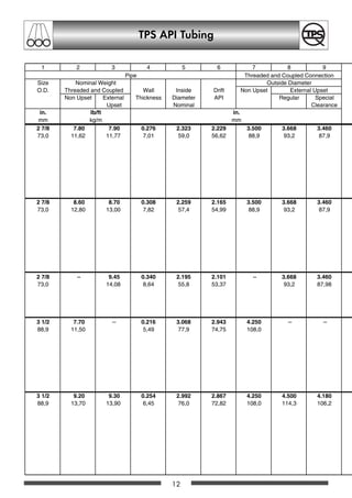
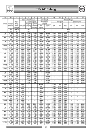


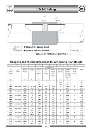
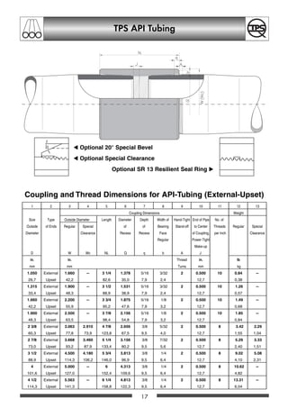


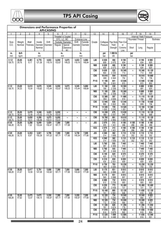
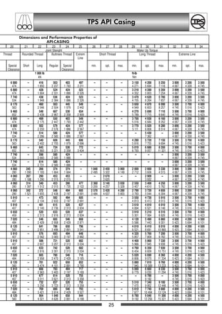


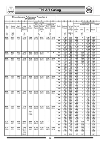


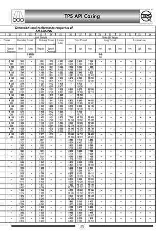
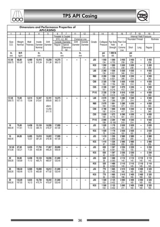


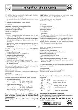


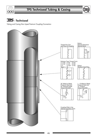


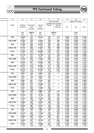


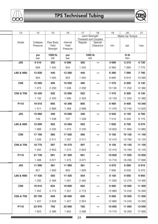


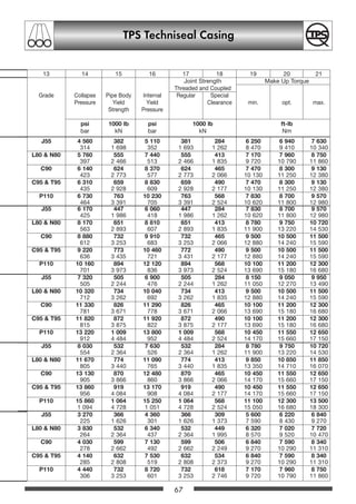

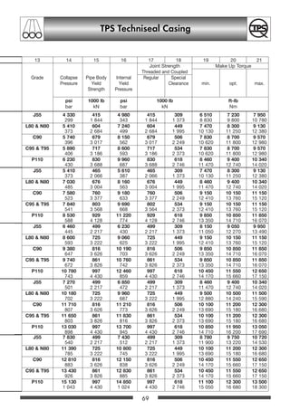


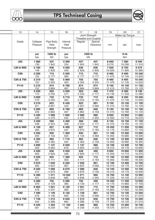


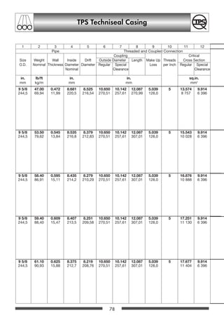


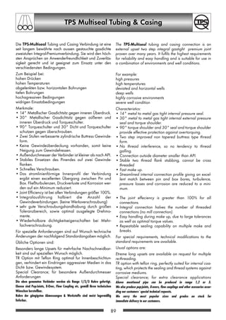
![TPS Multiseal Tubing TS 8
90
3LSH RQQHFWLRQ
2XWVLGH 'LDPHWHU
6L]H :HLJKW :DOO ,QVLGH 'ULIW 6WDQGDUG 6SHFLDO ,QVLGH 0DNH 8S 7KUHDGV -RLQW
2' 1RPLQDO 7KLFNQHVV 'LDPHWHU 'LDPHWHU OHDUDQFH 'LDPHWHU /RVV SHU ,QFK (IILFLHQF
1RPLQDO
LQ OEIW LQ LQ
PP NJP PP PP
Note:*notavailableasTPS-MULTISEAL-TS8TR
OCTGgesamt 88-117 20.12.2002 14:44 Uhr Seite 90](https://image.slidesharecdn.com/tubingstandard-180816141547/85/Tubing-standard-90-320.jpg)


![92
TPS Multiseal Tubing TS 8
3LSH RQQHFWLRQ
2XWVLGH 'LDPHWHU
6L]H :HLJKW :DOO ,QVLGH 'ULIW 6WDQGDUG 6SHFLDO ,QVLGH 0DNH 8S 7KUHDGV -RLQW
2' 1RPLQDO 7KLFNQHVV 'LDPHWHU 'LDPHWHU OHDUDQFH 'LDPHWHU /RVV SHU ,QFK (IILFLHQF
1RPLQDO
LQ OEIW LQ LQ
PP NJP PP PP
Note:*notavailableasTPS-MULTISEAL-TS8TR
OCTGgesamt 88-117 20.12.2002 14:44 Uhr Seite 92](https://image.slidesharecdn.com/tubingstandard-180816141547/85/Tubing-standard-93-320.jpg)


![96
TPS Multiseal Tubing TS 8
3LSH RQQHFWLRQ
2XWVLGH 'LDPHWHU
6L]H :HLJKW :DOO ,QVLGH 'ULIW 6WDQGDUG 6SHFLDO ,QVLGH 0DNH 8S 7KUHDGV -RLQW
2' 1RPLQDO 7KLFNQHVV 'LDPHWHU 'LDPHWHU OHDUDQFH 'LDPHWHU /RVV SHU ,QFK (IILFLHQF
1RPLQDO
LQ OEIW LQ LQ
PP NJP PP PP
OCTGgesamt 88-117 20.12.2002 14:44 Uhr Seite 96](https://image.slidesharecdn.com/tubingstandard-180816141547/85/Tubing-standard-99-320.jpg)
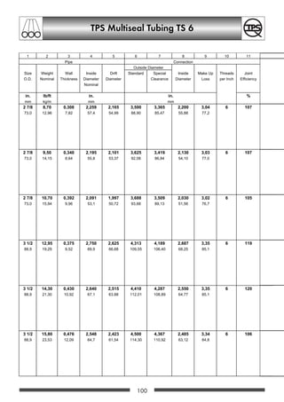
![98
TPS Multiseal Tubing TS 8
3LSH RQQHFWLRQ
2XWVLGH 'LDPHWHU
6L]H :HLJKW :DOO ,QVLGH 'ULIW 6WDQGDUG 6SHFLDO ,QVLGH 0DNH 8S 7KUHDGV -RLQW
2' 1RPLQDO 7KLFNQHVV 'LDPHWHU 'LDPHWHU OHDUDQFH 'LDPHWHU /RVV SHU ,QFK (IILFLHQF
1RPLQDO
LQ ,EIW LQ LQ
PP NJP PP PP
OCTGgesamt 88-117 20.12.2002 14:44 Uhr Seite 98](https://image.slidesharecdn.com/tubingstandard-180816141547/85/Tubing-standard-101-320.jpg)


![100
TPS Multiseal Tubing TS 6
3LSH RQQHFWLRQ
2XWVLGH 'LDPHWHU
6L]H :HLJKW :DOO ,QVLGH 'ULIW 6WDQGDUG 6SHFLDO ,QVLGH 0DNH 8S 7KUHDGV -RLQW
2' 1RPLQDO 7KLFNQHVV 'LDPHWHU 'LDPHWHU OHDUDQFH 'LDPHWHU /RVV SHU ,QFK (IILFLHQF
1RPLQDO
LQ ,EIW LQ LQ
PP NJP PP PP
OCTGgesamt 88-117 20.12.2002 14:44 Uhr Seite 100](https://image.slidesharecdn.com/tubingstandard-180816141547/85/Tubing-standard-104-320.jpg)
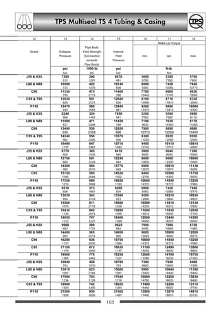

![102
TPS Multiseal Tubing TS 6
3LSH RQQHFWLRQ
2XWVLGH 'LDPHWHU
6L]H :HLJKW :DOO ,QVLGH 'ULIW 6WDQGDUG 6SHFLDO ,QVLGH 0DNH 8S 7KUHDGV -RLQW
2' 1RPLQDO 7KLFNQHVV 'LDPHWHU 'LDPHWHU OHDUDQFH 'LDPHWHU /RVV SHU ,QFK (IILFLHQF
1RPLQDO
LQ ,EIW LQ LQ
PP NJP PP PP
OCTGgesamt 88-117 20.12.2002 14:44 Uhr Seite 102](https://image.slidesharecdn.com/tubingstandard-180816141547/85/Tubing-standard-107-320.jpg)


![104
TPS Multiseal TS 4 Tubing Casing
3LSH RQQHFWLRQ
2XWVLGH 'LDPHWHU
6L]H :HLJKW :DOO ,QVLGH 'ULIW 6WDQGDUG 6SHFLDO ,QVLGH 0DNH 8S 7KUHDGV -RLQW
2' 1RPLQDO 7KLFNQHVV 'LDPHWHU 'LDPHWHU OHDUDQFH 'LDPHWHU /RVV SHU ,QFK (IILFLHQF
1RPLQDO
LQ ,EIW LQ LQ
PP NJP PP PP
OCTGgesamt 88-117 20.12.2002 14:44 Uhr Seite 104](https://image.slidesharecdn.com/tubingstandard-180816141547/85/Tubing-standard-110-320.jpg)


![106
TPS Multiseal TS 4 Tubing Casing
3LSH RQQHFWLRQ
2XWVLGH 'LDPHWHU
6L]H :HLJKW :DOO ,QVLGH 'ULIW 6WDQGDUG 6SHFLDO ,QVLGH 0DNH 8S 7KUHDGV -RLQW
2' 1RPLQDO 7KLFNQHVV 'LDPHWHU 'LDPHWHU OHDUDQFH 'LDPHWHU /RVV SHU ,QFK (IILFLHQF
1RPLQDO
LQ ,EIW LQ LQ
PP NJP PP PP
OCTGgesamt 88-117 20.12.2002 14:44 Uhr Seite 106](https://image.slidesharecdn.com/tubingstandard-180816141547/85/Tubing-standard-113-320.jpg)


![108
TPS Multiseal TS 4 Tubing Casing
3LSH RQQHFWLRQ
2XWVLGH 'LDPHWHU
6L]H :HLJKW :DOO ,QVLGH 'ULIW 6WDQGDUG 6SHFLDO ,QVLGH 0DNH 8S 7KUHDGV -RLQW
2' 1RPLQDO 7KLFNQHVV 'LDPHWHU 'LDPHWHU OHDUDQFH 'LDPHWHU /RVV SHU ,QFK (IILFLHQF
1RPLQDO
LQ ,EIW LQ LQ
PP NJP PP PP
OCTGgesamt 88-117 20.12.2002 14:44 Uhr Seite 108](https://image.slidesharecdn.com/tubingstandard-180816141547/85/Tubing-standard-116-320.jpg)


![TPS Multiseal TS 4 Tubing Casing
110
3LSH RQQHFWLRQ
2XWVLGH 'LDPHWHU
6L]H :HLJKW :DOO ,QVLGH 'ULIW 6WDQGDUG 6SHFLDO ,QVLGH 0DNH 8S 7KUHDGV -RLQW
2' 1RPLQDO 7KLFNQHVV 'LDPHWHU 'LDPHWHU OHDUDQFH 'LDPHWHU /RVV SHU ,QFK (IILFLHQF
1RPLQDO
LQ ,EIW LQ LQ
PP NJP PP PP
OCTGgesamt 88-117 20.12.2002 14:44 Uhr Seite 110](https://image.slidesharecdn.com/tubingstandard-180816141547/85/Tubing-standard-119-320.jpg)